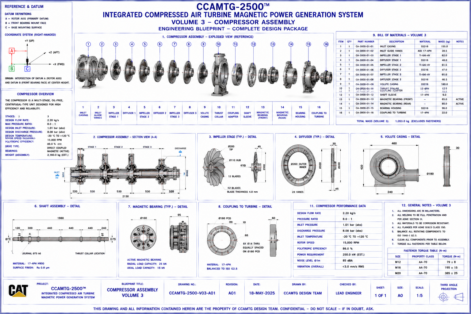
CCAMTG‑2500™ Compressor Assembly
This page presents the engineering documentation for the CCAMTG‑2500™ Compressor Assembly corresponding
to Blueprint Volume 03. It describes the conceptual compressor subsystem, component relationships,
airflow path, interfaces, materials, assembly philosophy, and maintenance considerations.
Document Reference
System: CCAMTG‑2500™ Integrated Compressed Air Turbine Magnetic Power Generation System
Volume: 03 — Compressor Assembly
Document Number: CAT‑809305‑V03‑DOC‑A03
Revision: A03
Classification: Engineering Concept Documentation
Units: Millimetres (mm), kilograms (kg), bar(g), °C
Document Purpose
This document provides the engineering description of the CCAMTG‑2500™ Compressor Assembly
corresponding to Blueprint Volume 03. It explains the subsystem architecture, component functions,
airflow path, interfaces, materials, assembly sequence, and maintenance considerations. It accompanies
the Volume 03 A0 blueprint sheet and should be read together with the associated engineering drawings.
System Overview
The Compressor Assembly is the first energy‑transfer stage within the CCAMTG‑2500™ architecture. It
increases the pressure of the working fluid before delivery to the pressure vessel and turbine stages.
The subsystem is organized to support:
- Independent servicing
- Simplified inspection
- Repeatable assembly
- Integration with magnetic bearing support
- Compatibility with adjacent assemblies
Compressor Functional Description
The compressor subsystem performs the following conceptual functions:
- Receives conditioned airflow from the intake system
- Increases working‑air pressure through staged compression
- Delivers compressed air to the pressure vessel
- Minimizes flow separation and turbulence
- Supports stable rotor operation
- Interfaces with cooling and instrumentation systems
The compressor is supported by the shaft and magnetic bearing system to maintain concentric operation
within the housing.
Compressor Assembly Architecture
The compressor assembly consists of:
- Compressor Housing
- Front End Cover
- Rear End Cover
- Compressor Rotor
- Impeller / Staged Compression Elements
- Main Shaft Interface
- Inlet Guide Section
- Discharge Volute
- Labyrinth Seal Assemblies
- Bearing Support Interfaces
- Instrumentation Ports
- Fastener Set
- Alignment Dowels
Each component is identified in Blueprint Volume 03 using exploded‑view callouts and part numbers.
Major Components
Compressor Housing
- Structural support
- Pressure containment
- Alignment of rotating components
- Mounting interface to adjacent assemblies
Compressor Rotor
- Compression of working fluid
- Transfer of mechanical energy
- Rotor balance
- Torque transmission through the shaft
Impeller / Compression Stages
- Accelerate working fluid
- Increase pressure through staged energy transfer
- Direct flow toward diffuser section
Diffuser Section
- Convert velocity into pressure
- Improve flow stability
- Reduce outlet turbulence
Discharge Volute
- Collect compressed flow
- Deliver air uniformly toward the pressure vessel interface
Labyrinth Seal Assembly
- Reduce leakage
- Separate pressure regions
- Protect bearing cavities
Rotor Assembly
The rotor assembly includes:
- Main Rotor
- Shaft Interface
- Balance Features
- Coupling Hub
- Seal Running Surfaces
- Bearing Journals
Design objectives:
- Concentric rotation
- Reduced vibration
- Modular replacement
- Balance correction capability
Rotor balance verification is documented in Volume 25.
Housing Assembly
The housing assembly comprises:
- Main Casing
- End Covers
- Flanged Connections
- Seal Grooves
- Inspection Covers
- Mounting Pads
- Instrument Ports
The housing is intended to support:
- Pressure loads
- Thermal expansion
- Mechanical alignment
- Maintenance accessibility
Shaft Interface
The compressor is connected to the common machine shaft.
Interface functions:
- Torque transmission
- Rotor positioning
- Bearing support
- Dynamic alignment
The shaft interfaces with:
- Volume 05 — Turbine Assembly
- Volume 06 — Magnetic Bearing System
Airflow Path
Conceptual airflow sequence:
- Air Intake System
- Compressor Inlet Guide
- Compressor Rotor
- Diffuser Section
- Discharge Volute
- Pressure Vessel
Flow objectives:
- Uniform inlet velocity
- Controlled pressure increase
- Stable discharge characteristics
- Reduced recirculation
Mechanical Interfaces
Interfaces include:
- Air Intake Assembly (Volume 02)
- Pressure Vessel (Volume 04)
- Shaft Assembly
- Magnetic Bearings (Volume 06)
- Cooling System (Volume 07)
- Instrumentation (Volume 08)
- Structural Frame (Volume 09)
Materials
Representative material selections:
- Compressor Housing: Stainless Steel 316
- Rotor: Titanium Alloy Ti‑6Al‑4V
- Shaft: Alloy Steel
- Diffuser: Stainless Steel 316
- Volute: Stainless Steel 316
- Labyrinth Seals: Stainless Steel
- Fasteners: Stainless Steel
- Dowels: Hardened Steel
Material selections emphasize corrosion resistance, mechanical strength, and compatibility with the
conceptual operating environment.
Assembly Procedure
Recommended sequence:
- Prepare housing
- Install alignment dowels
- Fit labyrinth seals
- Install rotor onto shaft
- Install bearing interfaces
- Position end covers
- Install fasteners
- Verify concentricity
- Rotate shaft manually for clearance check
- Complete inspection
Manufacturing Considerations
General manufacturing guidance:
- Machine rotor journals to specified tolerances
- Finish sealing surfaces
- Deburr all edges
- Inspect critical bores
- Maintain concentricity between rotor and housing
- Verify flange flatness before assembly
Detailed manufacturing drawings are contained in Volume 14.
Inspection Requirements
Inspection activities include:
- Visual inspection
- Rotor dimensional verification
- Housing bore inspection
- Shaft alignment check
- Seal groove inspection
- Fastener verification
- Concentricity measurement
- Rotor balance verification (see Volume 25)
Maintenance Procedures
Routine maintenance includes:
- Inspect compressor rotor
- Examine seal wear
- Verify fastener torque
- Clean airflow passages
- Inspect bearing interfaces
- Check alignment after maintenance
- Replace damaged seals as required
Safety Considerations
Before maintenance:
- Isolate machine
- Depressurize system
- Lock out electrical systems
- Verify rotor has stopped
- Follow pressure‑system safety procedures
- Wear appropriate PPE
Design Specifications
The compressor assembly is intended to provide:
- Stable pressure generation
- Modular construction
- Efficient airflow routing
- Reliable shaft interface
- Serviceability
- Structural rigidity
- Integration with cooling and instrumentation systems
Engineering Reference Data
Associated blueprint: Volume 03 — Compressor Assembly
Drawing package includes:
- Exploded assembly
- Orthographic views
- Longitudinal sections
- Cross‑sections
- Interface drawings
- Bill of Materials
- Assembly details
- Reference dimensions
Related Documents
- Volume 01 — Master General Arrangement
- Volume 02 — Air Intake System
- Volume 04 — Pressure Vessel
- Volume 05 — Turbine Assembly
- Volume 06 — Magnetic Bearing System
- Volume 07 — Airflow & Cooling System
- Volume 08 — Piping & Instrumentation
- Volume 11 — Fastener Package
- Volume 14 — Manufacturing, Inspection & QA
- Volume 25 — Rotor Dynamics Engineering
Document Status
- Document Title: Compressor Assembly Engineering Documentation
- Document Number: CAT‑809305‑V03‑DOC‑A03
- Revision: A03
- Classification: Engineering Concept Documentation
- Package: CCAMTG‑2500™ Complete Engineering Blueprint Package
- Associated Blueprint: Volume 03 — Compressor Assembly
Conceptual Engineering Package Notice
The Compressor Assembly documentation for CCAMTG‑2500™ is provided as conceptual engineering
information. It is intended for design study, modelling, and system integration activities and is not
sufficient by itself to manufacture or certify a working industrial machine.