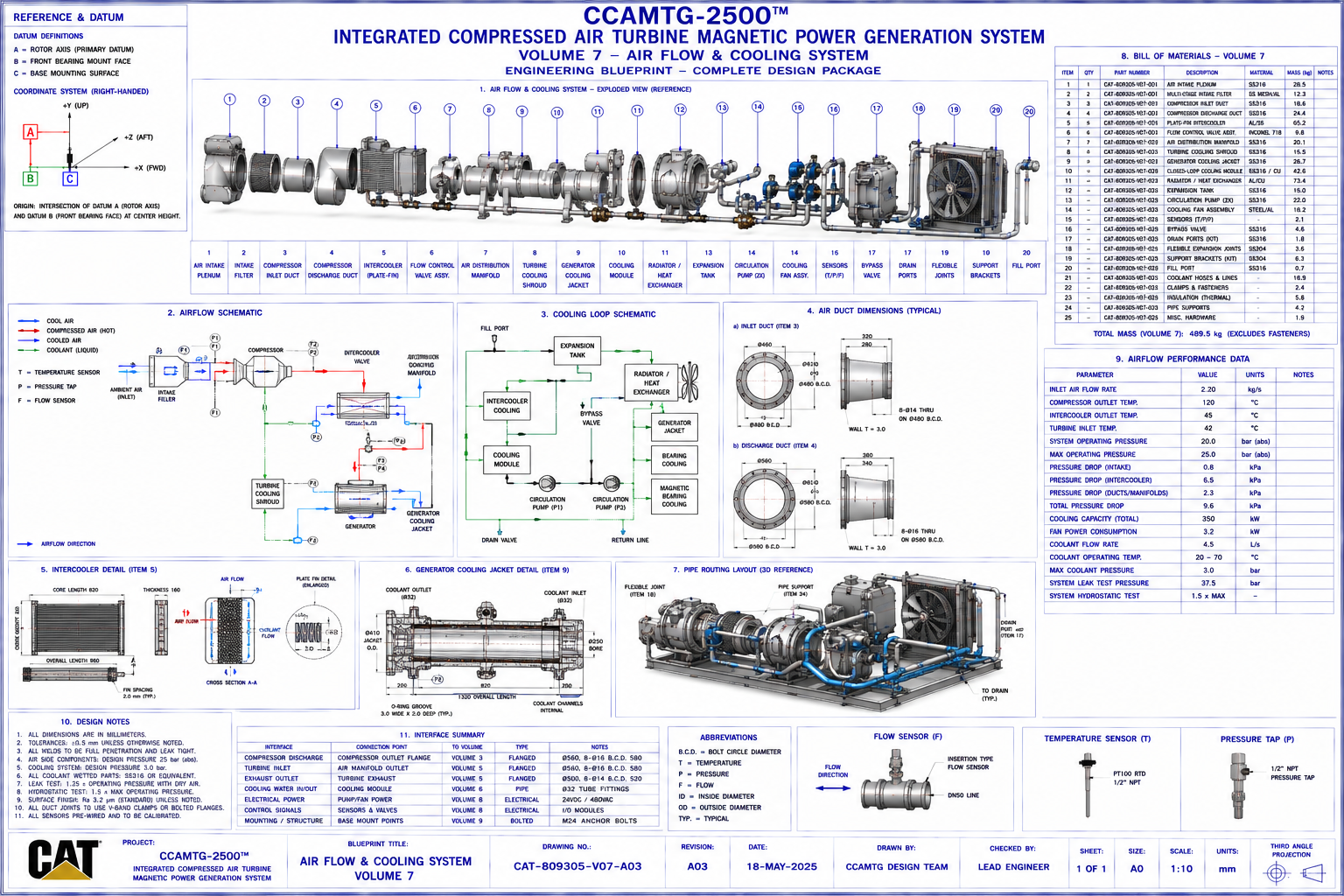
CCAMTG‑2500™ Airflow & Cooling System
This page presents the engineering documentation for the CCAMTG‑2500™ Airflow & Cooling System
corresponding to Blueprint Volume 07. The system manages compressed‑air routing and thermal control
across the compressor, turbine, generator, magnetic bearings, and associated equipment.
Document Reference
System: CCAMTG‑2500™ Integrated Compressed Air Turbine Magnetic Power Generation System
Volume: 07 — Airflow & Cooling System
Document Number: CAT‑809305‑V07‑DOC‑A03
Revision: A03
Classification: Engineering Concept Documentation
Units: mm, kg, bar(g), °C, L/min, m³/h
Document Purpose
This document provides the engineering description of the CCAMTG‑2500™ Airflow & Cooling System. It
explains subsystem architecture, component functions, airflow routing, cooling circuits, interfaces,
materials, assembly sequence, and maintenance considerations. It accompanies Blueprint Volume 07 and
provides supporting engineering information for the conceptual design.
System Overview
The airflow and cooling system performs two primary functions:
- Controlled routing of the working compressed‑air circuit
- Thermal management of mechanical, electrical, and electromagnetic subsystems
The system interfaces with:
- Air Intake System
- Compressor Assembly
- Pressure Vessel
- Turbine Assembly
- Generator Assembly
- Magnetic Bearing System
- Electrical Cabinets
- Instrumentation Network
Functional Description
The airflow and cooling system performs the following conceptual functions:
- Directs compressed air between subsystems
- Reduces discharge temperatures through intercooling
- Removes waste heat from rotating equipment
- Maintains magnetic bearing operating temperature
- Cools generator windings
- Protects electrical equipment
- Stabilizes system operating temperatures
- Provides continuous coolant circulation
Airflow & Cooling System Architecture
The complete assembly consists of:
- Air Intake Plenum
- Multi‑Stage Air Filter
- Compressor Inlet Duct
- Compressor Discharge Duct
- Plate‑Fin Intercooler
- Flow Distribution Manifold
- Turbine Inlet Duct
- Turbine Exhaust Duct
- Generator Cooling Jacket
- Magnetic Bearing Cooling Jacket
- Closed‑Loop Liquid Cooling Circuit
- Radiator Assembly
- Heat Exchanger
- Expansion Tank
- Dual Coolant Pumps
- Cooling Fan Assembly
- Bypass Valve
- Drain Valves
- Fill Port
- Flexible Expansion Joints
- Pipe Supports
- Temperature Sensors
- Pressure Sensors
- Flow Sensors
Major Components
Air Intake Plenum
- Receives incoming air
- Equalizes airflow distribution
- Supports filtration system
- Minimizes intake turbulence
Compressor Discharge Duct
- Transfers compressed air
- Maintains pressure integrity
- Directs flow to intercooler
- Minimizes pressure loss
Plate‑Fin Intercooler
- Removes compression heat
- Increases air density
- Improves downstream efficiency
- Reduces thermal loading
Air Distribution Manifold
- Evenly distributes airflow
- Reduces flow imbalance
- Directs air to turbine inlet
- Supports instrumentation
Generator Cooling Jacket
- Removes generator heat
- Maintains winding temperature
- Supports continuous operation
Magnetic Bearing Cooling Jacket
- Removes heat from electromagnets
- Protects coil insulation
- Maintains controller stability
Radiator Assembly
- Rejects waste heat
- Cools circulating coolant
- Supports thermal equilibrium
Expansion Tank
- Accommodates coolant expansion
- Removes trapped air
- Stabilizes coolant pressure
Dual Circulation Pumps
- Maintain coolant flow
- Provide system redundancy
- Ensure continuous cooling
Air Intake & Distribution System
The airflow routing includes:
- Intake plenum
- Filtration system
- Compressor inlet
- Compressor discharge
- Intercooler
- Distribution manifold
- Turbine inlet
- Turbine exhaust
- Closed‑loop return circuit
Primary design objectives:
- Uniform airflow
- Low pressure loss
- Stable flow conditions
- Reduced turbulence
Intercooler Assembly
The intercooler assembly includes:
- Plate‑fin core
- End tanks
- Cooling passages
- Mounting brackets
- Drain ports
- Temperature sensors
- Pressure taps
Primary functions:
- Reduce compressed‑air temperature
- Increase air density
- Protect downstream components
- Improve thermodynamic performance
Closed‑Loop Cooling Circuit
The liquid cooling circuit comprises:
- Expansion tank
- Primary pump
- Secondary pump
- Generator cooling jacket
- Magnetic bearing cooling jacket
- Heat exchanger
- Radiator
- Cooling fan
- Return manifold
Operating objectives:
- Stable coolant flow
- Uniform temperature distribution
- Continuous circulation
- Air removal capability
Cooling Jacket Assemblies
Cooling jackets are installed on:
- Generator housing
- Magnetic bearing housings
- Controller power modules
- Selected structural components
Each jacket provides:
- Internal coolant passages
- Sealed interfaces
- Service connections
- Temperature monitoring
Radiator & Heat Exchanger Module
The heat rejection module includes:
- Plate heat exchanger
- Radiator core
- Cooling fan
- Fan motor
- Shroud assembly
- Mounting frame
- Drain valves
Functions:
- Transfer heat to ambient air
- Maintain coolant operating temperature
- Support continuous operation
Pumps, Valves & Flow Control
The system includes:
- Primary circulation pump
- Secondary standby pump
- Flow control valve
- Bypass valve
- Isolation valves
- Drain valves
- Fill connection
- Pressure relief provisions
These components regulate coolant distribution throughout the system.
Instrumentation & Sensors
Installed instrumentation includes:
- Air temperature sensors
- Coolant temperature sensors
- Pressure transmitters
- Flow meters
- Differential pressure sensors
- Coolant level sensor
- Pump status indicators
- Fan speed monitoring
Instrumentation interfaces with:
- PLC
- HMI
- SCADA
- Digital Twin
- Alarm System
Materials
Representative material selections:
- Air Ducts: Stainless Steel 316L
- Cooling Pipes: Stainless Steel 304
- Radiator Core: Aluminium Alloy
- Heat Exchanger: Stainless Steel
- Expansion Tank: Stainless Steel
- Pump Housing: Cast Stainless Steel
- Valve Bodies: Stainless Steel
- Flexible Couplings: Reinforced Elastomer
- O‑Rings: Fluoroelastomer (FKM)
- Fasteners: Stainless Steel A4‑80
Material selections support corrosion resistance, pressure containment, thermal stability, and long
service life within the conceptual operating environment.
Assembly Procedure
Recommended assembly sequence:
- Install intake plenum
- Fit filtration system
- Install compressor ducts
- Mount intercooler
- Install distribution manifold
- Install cooling jackets
- Mount radiator assembly
- Install heat exchanger
- Install expansion tank
- Install pumps
- Connect coolant piping
- Install valves
- Install sensors
- Fill coolant circuit
- Perform leak inspection
Manufacturing Considerations
General manufacturing guidance:
- Form ductwork
- Machine flange faces
- Fabricate cooling manifolds
- Pressure‑test pipe assemblies
- Weld cooling jackets
- Machine sealing surfaces
- Inspect fabricated components
- Perform hydrostatic testing
Detailed manufacturing information is provided in Volumes 14, 23, and 24.
Inspection Requirements
Inspection activities include:
- Visual inspection
- Weld inspection
- Pressure testing
- Leak testing
- Flow verification
- Temperature sensor calibration
- Pump functional testing
- Valve operation checks
Maintenance Procedures
Routine maintenance includes:
- Air filter replacement
- Radiator cleaning
- Pump inspection
- Valve inspection
- Coolant replacement
- Leak inspection
- Sensor calibration
- Hose inspection
- Expansion tank inspection
Safety Considerations
Before maintenance:
- Depressurize air system
- Isolate coolant circuit
- Lock out electrical power
- Allow system to cool
- Drain coolant where required
- Verify zero pressure
- Wear appropriate PPE
Design Specifications
The airflow and cooling system is intended to provide:
- Stable airflow distribution
- Efficient thermal management
- Low pressure loss
- High reliability
- Modular maintenance
- Continuous circulation
- Integration with all major machine subsystems
- Compatibility with monitoring and control systems
Compatibility with monitoring and control systems
These specifications define the conceptual airflow and thermal‑management performance targets for the
CCAMTG‑2500™ system. All real‑world implementations require detailed engineering validation, CFD
analysis, thermodynamic modelling, and compliance with applicable industrial standards.
Engineering Reference Data
Associated blueprint: Volume 07 — Airflow & Cooling System
Drawing package includes:
- General Arrangement
- Exploded Assembly
- Airflow Schematic
- Cooling Loop Diagram
- Pipe Routing Layout
- Intercooler Details
- Cooling Jacket Details
- Orthographic Views
- Bill of Materials
- Dimensioned Reference Drawings
Related Documents
- Volume 01 — Master General Arrangement
- Volume 02 — Air Intake System
- Volume 03 — Compressor Assembly
- Volume 04 — Pressure Vessel
- Volume 05 — Turbine Assembly
- Volume 06 — Magnetic Bearing System
- Volume 08 — Piping & Instrumentation
- Volume 10 — Electrical Power Generation & Control
- Volume 17 — Control Logic & Automation Architecture
- Volume 18 — Performance Testing & Commissioning
- Volume 21 — Digital Twin, Simulation & Validation
- Volume 26 — Thermodynamic Engineering
- Volume 27 — CFD Engineering Package
Document Status
- Document Title: Airflow & Cooling System Engineering Documentation
- Document Number: CAT‑809305‑V07‑DOC‑A03
- Revision: A03
- Classification: Engineering Concept Documentation
- Package: CCAMTG‑2500™ Complete Engineering Blueprint Package
- Associated Blueprint: Volume 07 — Airflow & Cooling System
Conceptual Engineering Package Notice
The Airflow & Cooling System documentation for CCAMTG‑2500™ is provided as conceptual engineering
information. It is intended for design study, modelling, and system integration activities and is not
sufficient by itself to manufacture, certify, or deploy an industrial machine. All real‑world
engineering work must be performed and validated by qualified professionals using detailed
manufacturing drawings, tolerances, and certified component specifications.