
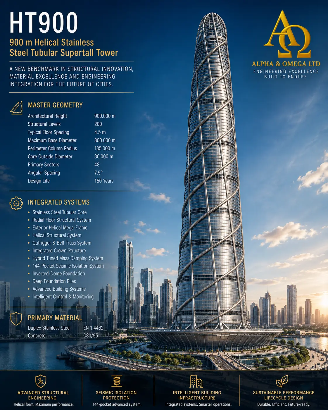
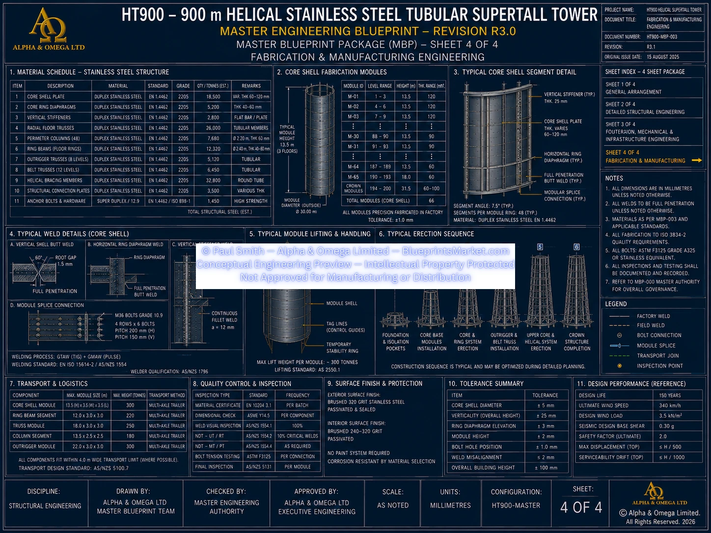
Explore the HT900 R3.0 conceptual engineering blueprint and technical documentation package for a 900 metre, 200-level helical stainless-steel tubular supertall tower, including the Duplex Stainless-Steel Tubular Core, exterior helical megaframe, radial floor structure, outrigger and belt-truss systems, seismic-isolation foundation, building systems and lifecycle engineering.
HT900 R3.0
900 m Helical Stainless-Steel Tubular Supertall Tower
A comprehensive next-generation conceptual engineering blueprint
and technical documentation package for a 900 metre helical
stainless-steel tubular supertall tower concept.
The HT900 R3.0 Master Blueprint Package establishes an integrated
conceptual engineering framework covering the primary structural
system, foundation and seismic isolation systems, radial floor
structure, exterior helical megaframe, outrigger and belt-truss
systems, crown structure, vertical transportation, mechanical,
electrical and plumbing systems, HVAC and environmental control,
fire and life safety, control systems, smart infrastructure,
structural monitoring, construction sequencing, maintenance
and access systems.
The purchasable HT900 R3.0 package is supplied as a coordinated
collection of high-resolution PNG conceptual engineering blueprint
sheets and DOCX technical engineering documentation. It is a
conceptual engineering package and is not a construction-ready,
fabrication-ready or professionally certified architectural or
engineering drawing set.
Global Building Definition
Architectural Height: 900 metres including crown
Structural Levels: 200
Typical Structural Level Spacing: 4.5 metres
Maximum Base Envelope Diameter: 300 metres
Tubular Structural Core Outside Diameter: 30 metres
Primary Structural Grid: 48 sectors at 7.5° spacing
Total Helical Rotation: 160°
Primary Structural Material: EN 1.4462 Duplex Stainless Steel
Next-Generation Structural Philosophy
The HT900 R3.0 concept is based around a fully integrated
tubular stainless-steel primary superstructure working together
with an isolated reinforced-concrete substructure and deep-pile
foundation system.
The principal structural architecture consists of:
✔ 30 metre diameter tubular Duplex Stainless Steel structural core
✔ 48-column tubular perimeter megaframe
✔ Two opposing principal helical bracing families
✔ Four concentric floor support rings plus the core interface
✔ 48-sector radial floor structural system
✔ Circumferential perimeter structural rings
✔ Triangulated outrigger and belt-truss systems
✔ Composite floor diaphragm system
✔ Integrated crown structural system
✔ Inverted-dome foundation and seismic isolation architecture
✔ Integrated structural health monitoring and digital lifecycle philosophy
Executive Technical Summary
The HT900 R3.0 Helical Stainless-Steel Tubular Supertall Tower is a
comprehensive master conceptual engineering blueprint and technical
documentation package defining the design philosophy, system interfaces
and coordinated technical framework for an advanced 900 metre
supertall tower concept.
The HT900 R3.0 architecture is based on a fully integrated structural
system comprising a 30 metre diameter tubular Duplex Stainless Steel core,
a 48-column perimeter tubular megaframe, opposing helical bracing systems,
radial floor structures, concentric support rings, outrigger and belt-truss
systems, an integrated crown structure, an inverted-dome foundation and
advanced seismic isolation architecture.
The wider conceptual engineering package also coordinates the principal
building systems, including vertical transportation, mechanical systems,
electrical power distribution, plumbing and drainage, HVAC and environmental
control, fire and life safety, control systems, smart infrastructure,
structural health monitoring, construction sequencing, maintenance and
access systems.
Every HT900 R3.0 blueprint and technical document is developed from the same
controlled conceptual engineering basis, including:
✔ Global building geometry
✔ Reference datums and structural levels
✔ 48-sector primary structural grid
✔ 7.5° primary angular spacing
✔ 160° total helical rotation
✔ Structural system relationships and interfaces
✔ Component and document identification conventions
✔ Material and engineering specification hierarchy
✔ Structural load-path philosophy
✔ Revision and document-control framework
✔ Structural health monitoring and digital lifecycle philosophy
This creates a unified conceptual engineering documentation system in which
the foundation, tubular core, radial floor system, exterior helical megaframe,
outrigger and belt-truss systems, crown structure and integrated building
services are developed from the same controlled HT900 design basis.
The purchased HT900 R3.0 package is supplied as high-resolution PNG
conceptual engineering blueprint sheets together with DOCX technical
engineering documentation. CAD files, BIM files, DWG/DXF files, Revit models,
IFC models and construction-ready architectural or engineering drawing files
are not included in the purchased package.
Integrated Conceptual Engineering Architecture
The HT900 Master Blueprint Package integrates the principal conceptual
engineering systems of the 900 metre Helical Stainless-Steel Tubular
Supertall Tower into one coordinated technical documentation framework.
The package covers:
✔ Master Engineering Blueprint Authority and master design basis
✔ Master Document Index and controlled document structure
✔ Global System Overview
✔ Global building geometry and structural configuration
✔ Stainless Steel Tubular Core
✔ Radial Floor Structural System
✔ Exterior Helical Megaframe
✔ Helical Structural System
✔ Outrigger & Belt-Truss System
✔ Crown Dome Structure
✔ Vertical Transportation System
✔ Mechanical, Plumbing & Drainage System
✔ Electrical Power Distribution System
✔ HVAC & Environmental Control System
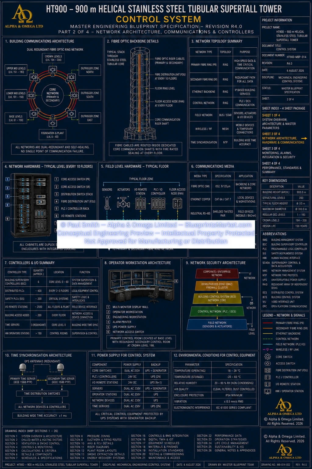
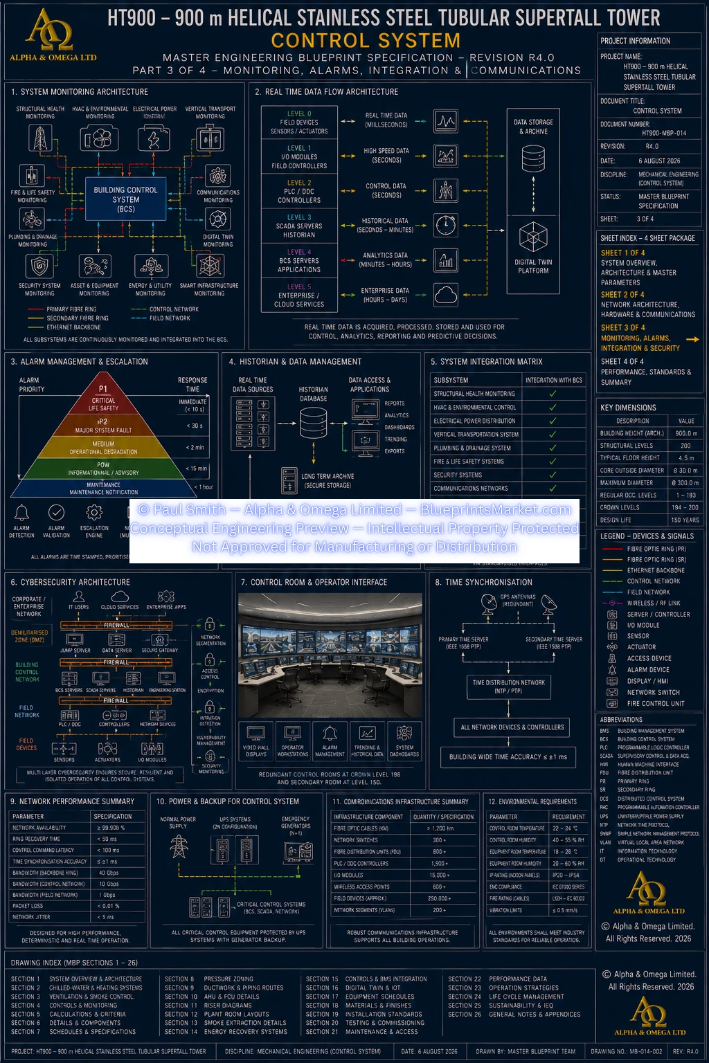
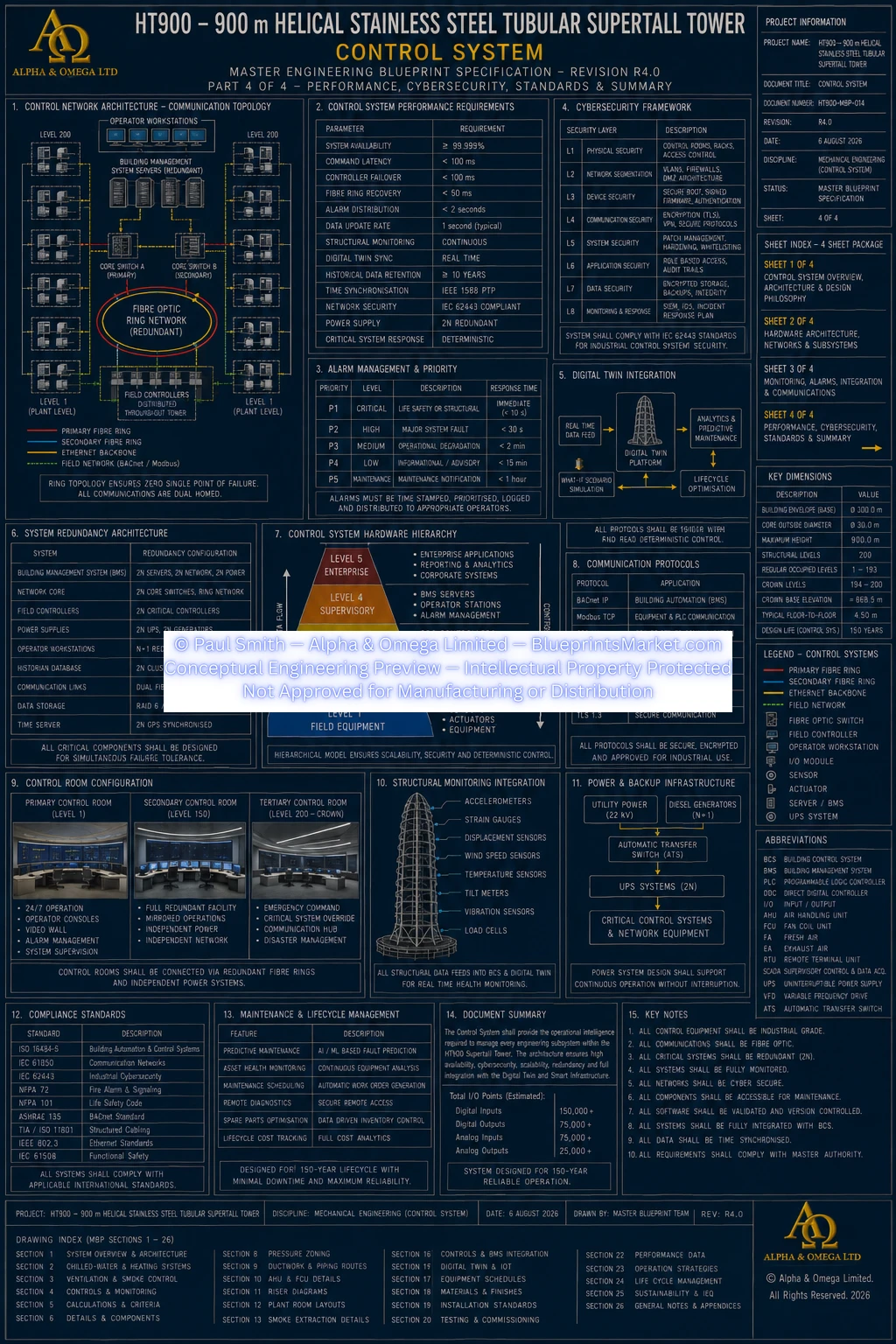
✔ Control System
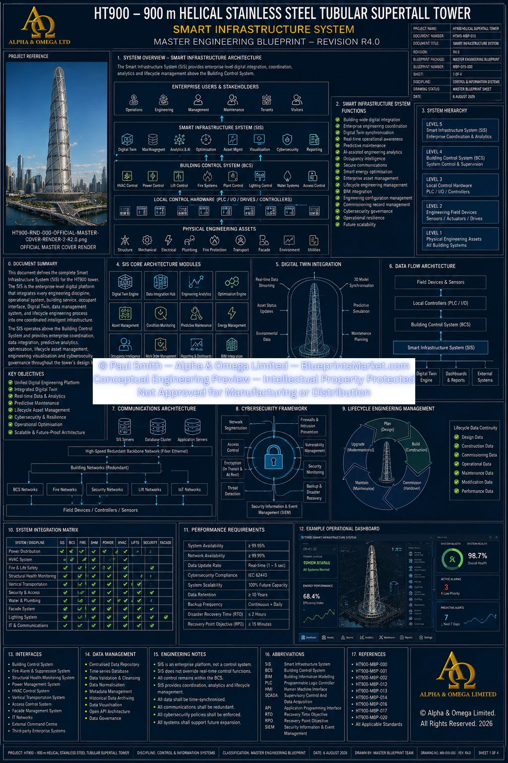
✔ Smart Infrastructure System
✔ Fire & Life Safety System
✔ Structural Connection Library
✔ Assembly & Fastener System
✔ Bill of Materials and foundation materials information
✔ Consolidated Master Parts Register
✔ Aerodynamic & Wind Engineering
✔ Tuned Mass Damping System
✔ Construction Sequencing and assembly methodology
✔ Maintenance & Access System
✔ Master Engineering Specifications
✔ Foundation, Inverted-Dome & Seismic Isolation System
Integrated Building Intelligence & Lifecycle Systems
The HT900 conceptual engineering architecture extends beyond the primary
structural system by coordinating the tower's monitoring, control,
operational, maintenance and lifecycle-management concepts.
The documented system architecture includes:
✔ Building control-system architecture
✔ Smart infrastructure integration
✔ Structural Health Monitoring concepts and sensor integration
✔ Building automation and monitoring concepts
✔ Electrical power-system monitoring and control
✔ Mechanical-system monitoring and control
✔ Plumbing and drainage monitoring concepts
✔ HVAC and environmental monitoring and control
✔ Fire and life-safety system integration
✔ Vertical transportation control integration
✔ Sensor and instrumentation architecture
✔ Structural condition and performance monitoring
✔ Digital component identification and traceability philosophy
✔ Digital inspection and maintenance-record philosophy
✔ Predictive maintenance concepts
✔ Permanent inspection and maintenance-access provisions
✔ Long-term structural monitoring and lifecycle-management philosophy
The HT900 package provides these systems as conceptual engineering
blueprints and supporting technical documentation. The purchased package
consists of high-resolution PNG conceptual blueprint files and DOCX
technical documents.
The HT900 package does not include CAD models, BIM models, Revit models,
DWG or DXF drawing files, IFC models, fabrication drawings,
construction-ready architectural drawings or professionally certified
construction engineering drawings. The conceptual package requires further
professional architectural and engineering development, analysis,
verification and conversion into project-specific construction documentation
before any real-world construction application.
Complete HT900 Master Blueprint & Technical Document Library
Access the complete public HT900 Master Blueprint Package library,
including the blueprint families, technical document groups,
system hierarchies and public file-reference structure.
The library reflects the current HT900 package organisation and
controlled file-naming structure, including the current revision
identifier assigned to each individual blueprint and technical document.
The purchasable package is supplied as high-resolution PNG conceptual
engineering blueprint files together with corresponding DOCX technical
engineering documentation.
Master Engineering Specifications
The HT900 Master Blueprint Package defines an integrated conceptual
engineering architecture for a 900 metre Helical Stainless-Steel Tubular
Supertall Tower.
The package establishes a coordinated technical framework across the
principal structural, foundation, building-services, control, safety,
construction and maintenance systems.
The documented systems maintain common project-wide references including:
✔ Global building geometry
✔ Structural level configuration
✔ Primary structural system relationships
✔ System and component identification
✔ Structural connection requirements
✔ Assembly and fastener requirements
✔ System interfaces
✔ Construction sequencing relationships
✔ Inspection and maintenance requirements
✔ Controlled document and revision relationships
The package is supplied as conceptual engineering blueprint PNG files
and supporting DOCX technical documentation. It does not include CAD
models, BIM models or construction-ready engineering drawings.
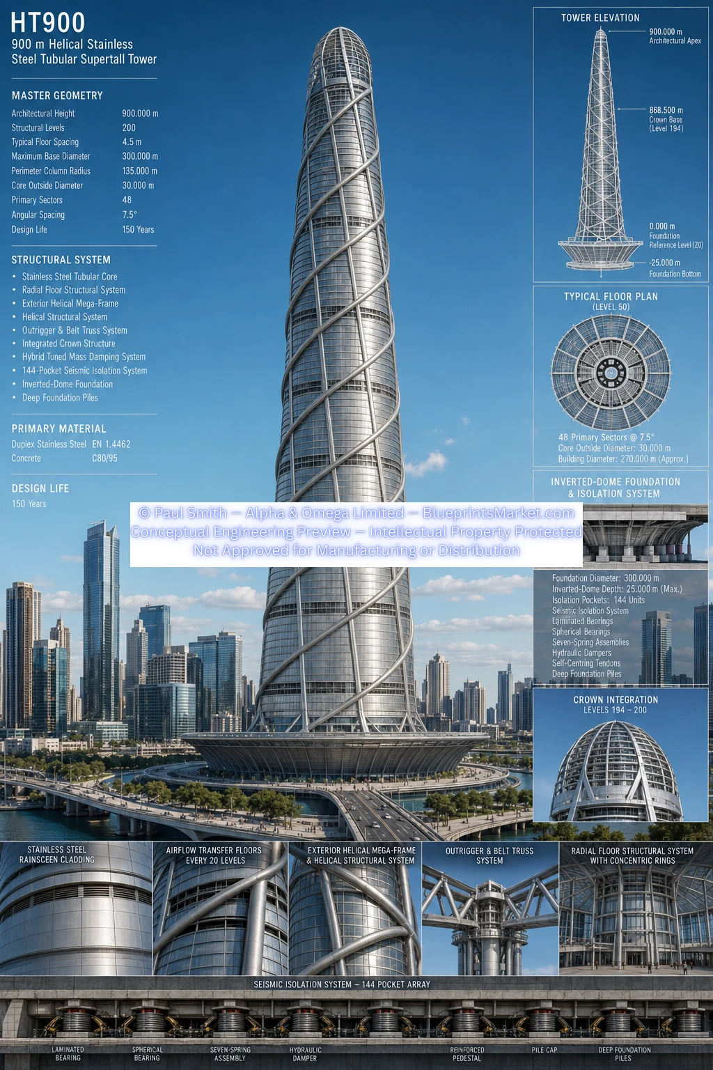
Primary Structural Geometry
Architectural Height: 900.0 metres
Structural Levels: 200
Typical Structural Level Height: 4.5 metres
Maximum Base Envelope Diameter: 300.0 metres
Maximum Base Radius: 150.0 metres
Tubular Core Diameter: 30.0 metres
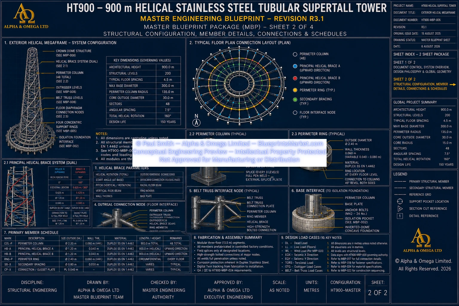
Primary Perimeter Grid: 48 sectors
Angular Spacing: 7.5°
Perimeter Column Centreline Radius: 135.0 metres
Total Helical Rotation: 160°
The tower combines its central Stainless Steel Tubular Core,
Radial Floor Structural System, Exterior Helical Megaframe,
Helical Structural System and Outrigger & Belt-Truss System
into a coordinated three-dimensional structural architecture.
Structural Material System
The HT900 structural material architecture is based primarily upon
high-performance stainless-steel structural systems, with material grades
assigned according to the requirements of the individual structural
component and connection.
Principal documented material applications include:
✔ Stainless-steel tubular structural members
✔ EN 1.4462 Duplex Stainless Steel structural members where specified
✔ Super Duplex Stainless Steel for higher-demand components where specified
✔ High-strength structural connection assemblies
✔ Welded and mechanically fastened structural interfaces
✔ Corrosion-resistant structural components
✔ Modular and prefabricated structural assemblies
The material philosophy supports structural performance, corrosion
resistance, inspectability, maintainability and the long-term lifecycle
objectives of the HT900 conceptual engineering architecture.
Stainless-Steel Tubular Structural Framework
The HT900 structural architecture is based upon an integrated
stainless-steel tubular structural system extending from the
foundation and seismic-isolation interfaces through the full
900 metre superstructure to the Crown Dome Structure.
Rather than relying upon the central core alone, the structural
concept integrates the Stainless Steel Tubular Core, Radial Floor
Structural System, Exterior Helical Megaframe, Helical Structural
System, Outrigger & Belt-Truss System and Crown Dome Structure
to establish multiple coordinated structural load paths.
Stainless Steel Tubular Core
The central structural system incorporates:
✔ 30.0 metre diameter Stainless Steel Tubular Core
✔ Primary internal structural spine
✔ Vertical gravity-load transfer
✔ Lateral and torsional structural participation
✔ Core transfer structures at principal outrigger levels
✔ Interfaces with the Radial Floor Structural System
✔ Interfaces with the Outrigger & Belt-Truss System
✔ Structural monitoring provisions
The Stainless Steel Tubular Core forms the primary internal
structural spine of the HT900 tower and works together with the
exterior structural systems rather than functioning as an
independent conventional reinforced-concrete core.
Exterior Helical Megaframe
The exterior structural architecture integrates:
✔ 48-sector primary perimeter structural grid
✔ Perimeter tubular structural columns
✔ Exterior Helical Megaframe
✔ Helical Structural System
✔ Radial Floor Structural System interfaces
✔ Continuous belt-truss structures at designated levels
✔ Principal outrigger coupling zones
✔ Crown structural interfaces
The exterior structural systems work together with the Stainless
Steel Tubular Core and floor structures to redistribute gravity,
wind, seismic, overturning and torsional actions through multiple
coordinated structural load paths.
Integrated Structural Component System
The HT900 Master Blueprint Package documents a coordinated
component-based conceptual structural architecture.
Major structural systems and components include:
Primary Components
✔ Stainless Steel Tubular Core assemblies
✔ Perimeter tubular structural column assemblies
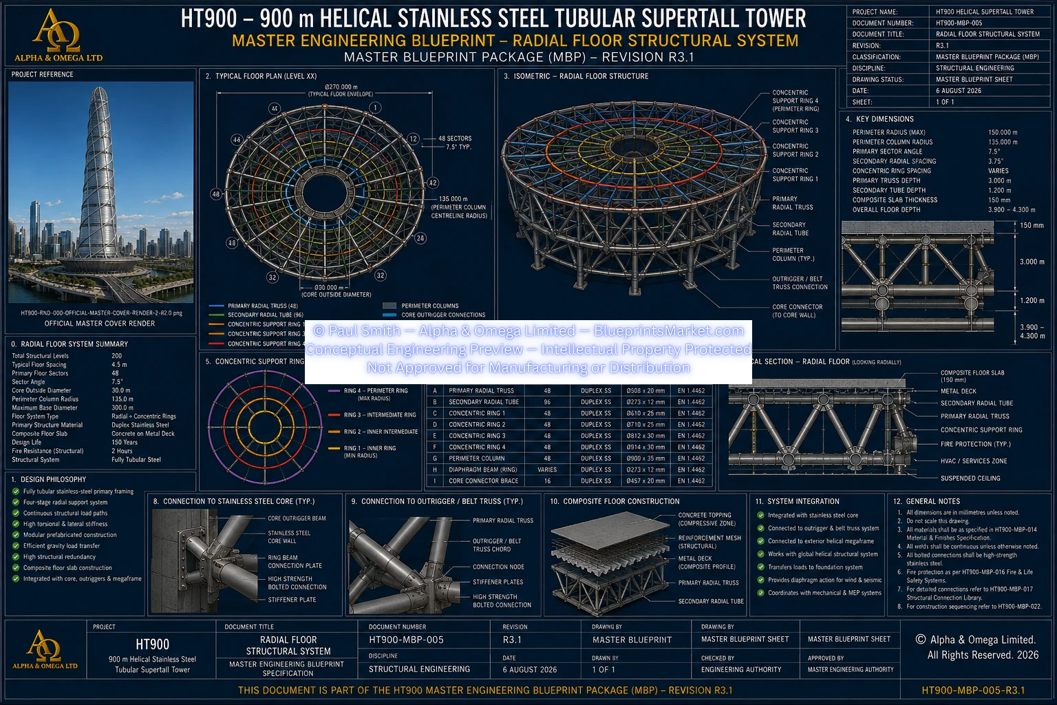
✔ Primary Radial Floor Trusses
✔ Four Concentric Support Rings
✔ Exterior Helical Megaframe members
✔ Helical structural members
✔ Core Transfer Rings
✔ Principal Outrigger Arms
✔ Triangulated outrigger web systems
✔ Continuous Belt Truss assemblies
✔ Structural node assemblies
✔ Crown Dome structural assemblies
✔ Foundation and seismic-isolation structural interfaces
Engineering Interfaces
✔ Structural Connection Library
✔ Assembly & Fastener System
✔ Welded structural connections
✔ Bolted structural connections
✔ Structural node assemblies
✔ Fabrication and erection interfaces
✔ Construction sequencing interfaces
✔ Inspection and Non-Destructive Testing requirements
✔ Structural Health Monitoring provisions
✔ Component identification and traceability
✔ Maintenance and permanent-access provisions
✔ Lifecycle inspection and monitoring concepts
HT900 Master Structural Engineering Framework
The structural architecture is defined across the coordinated
HT900 Master Blueprint Package rather than through the former
BM-SSS-900 V2 STR-200 designation.
The principal structural blueprint and technical-document families include:
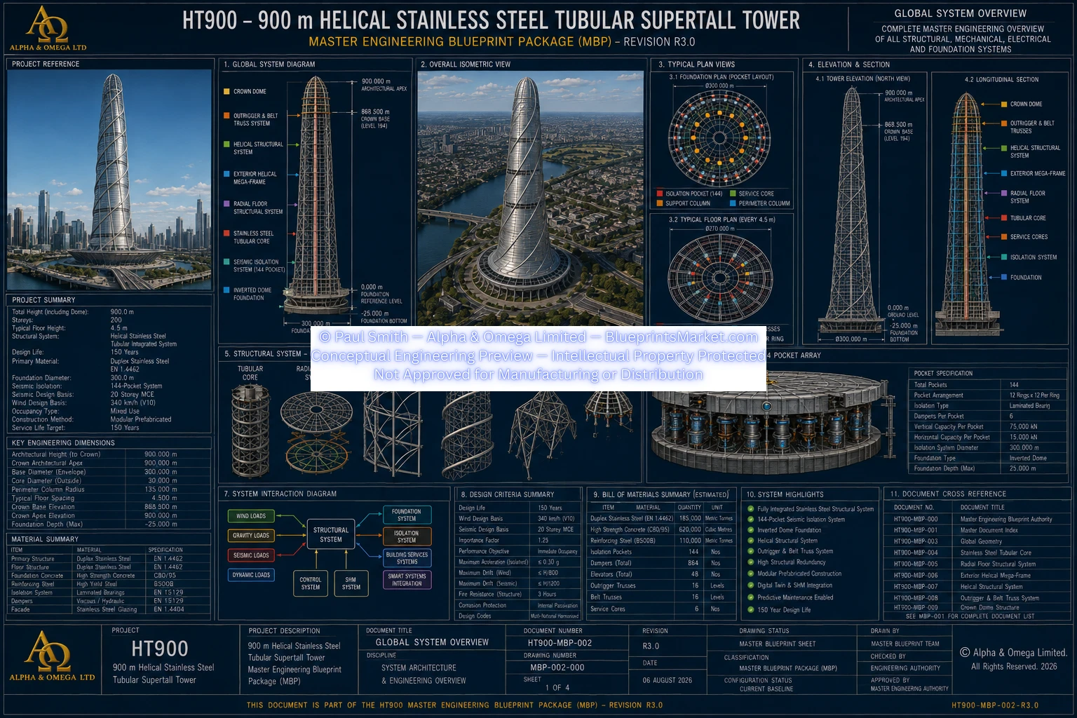
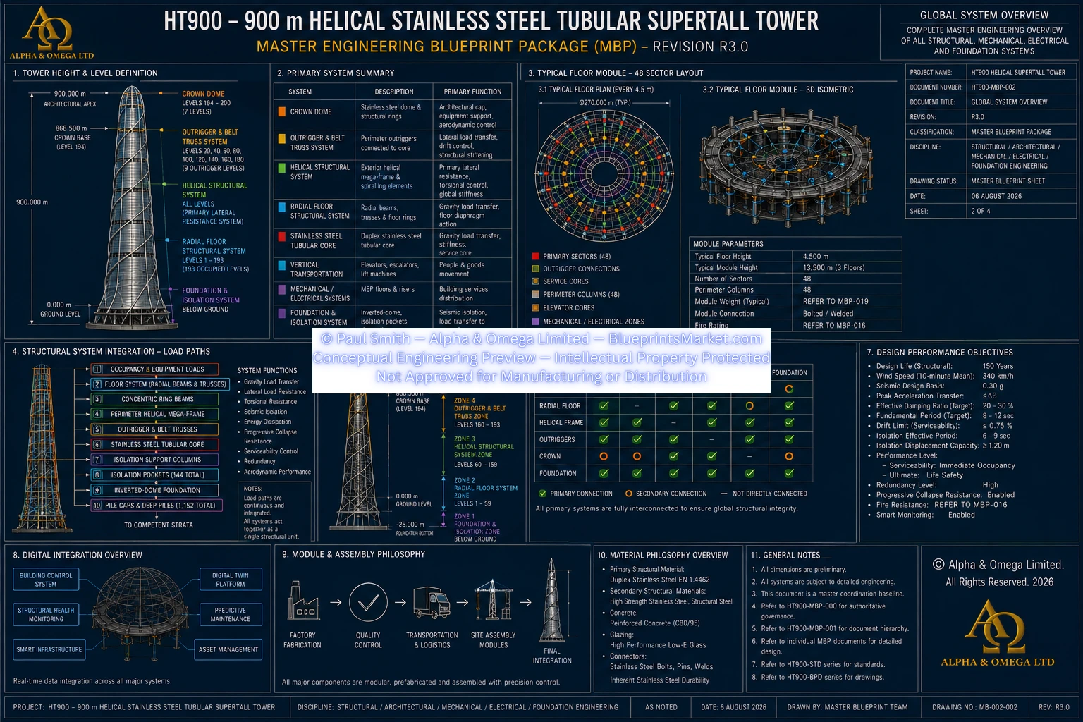
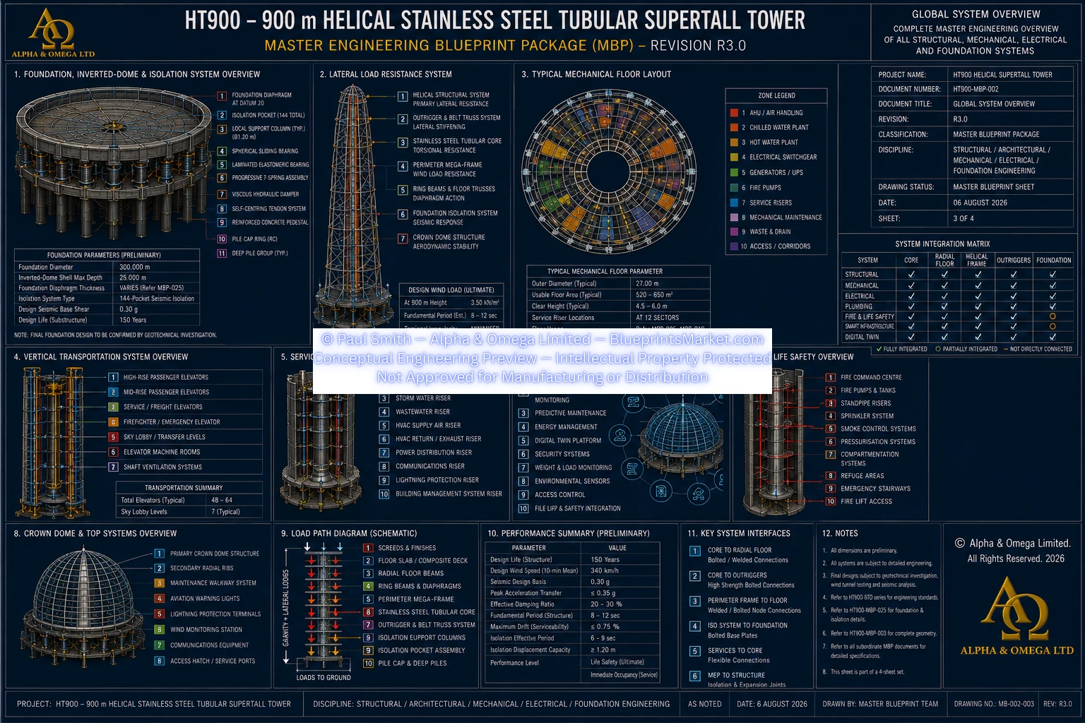
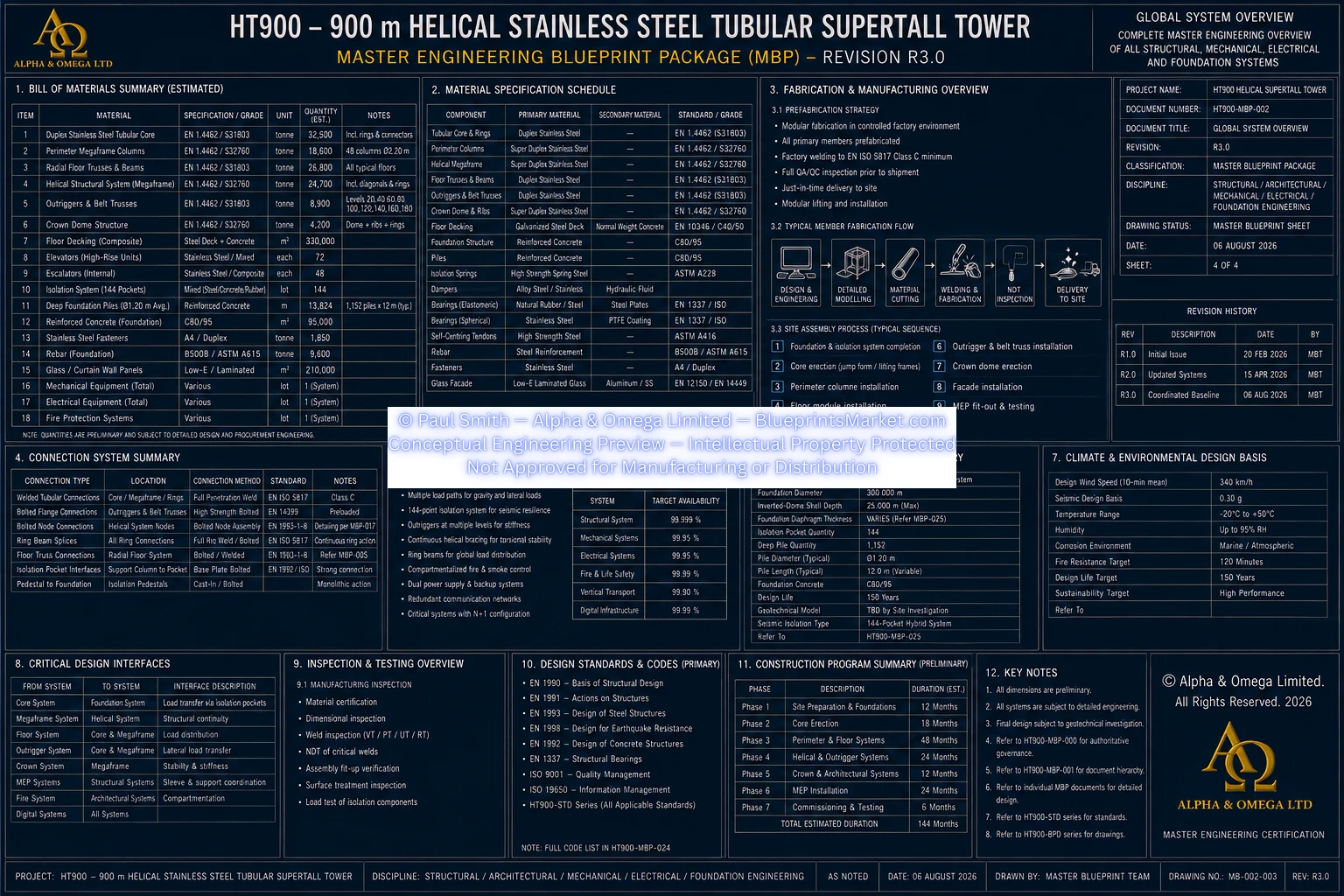
✔ HT900-MBP-002 — Global System Overview
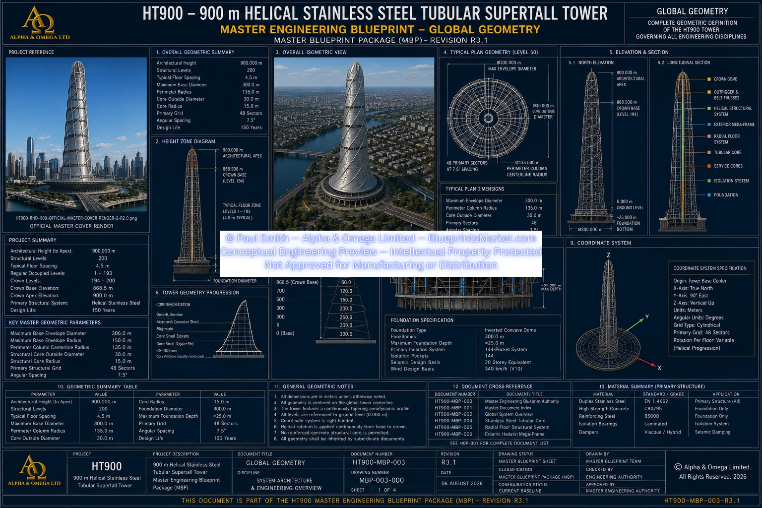
✔ HT900-MBP-003 — Global Geometry
✔ HT900-MBP-004 — Stainless Steel Tubular Core
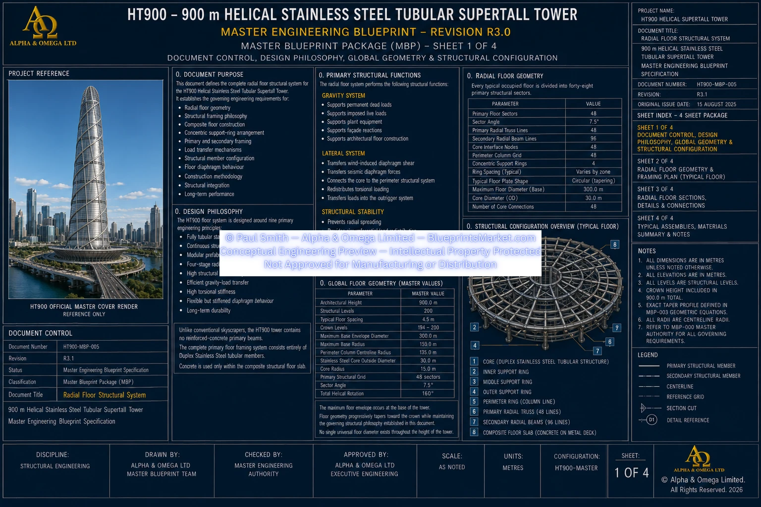
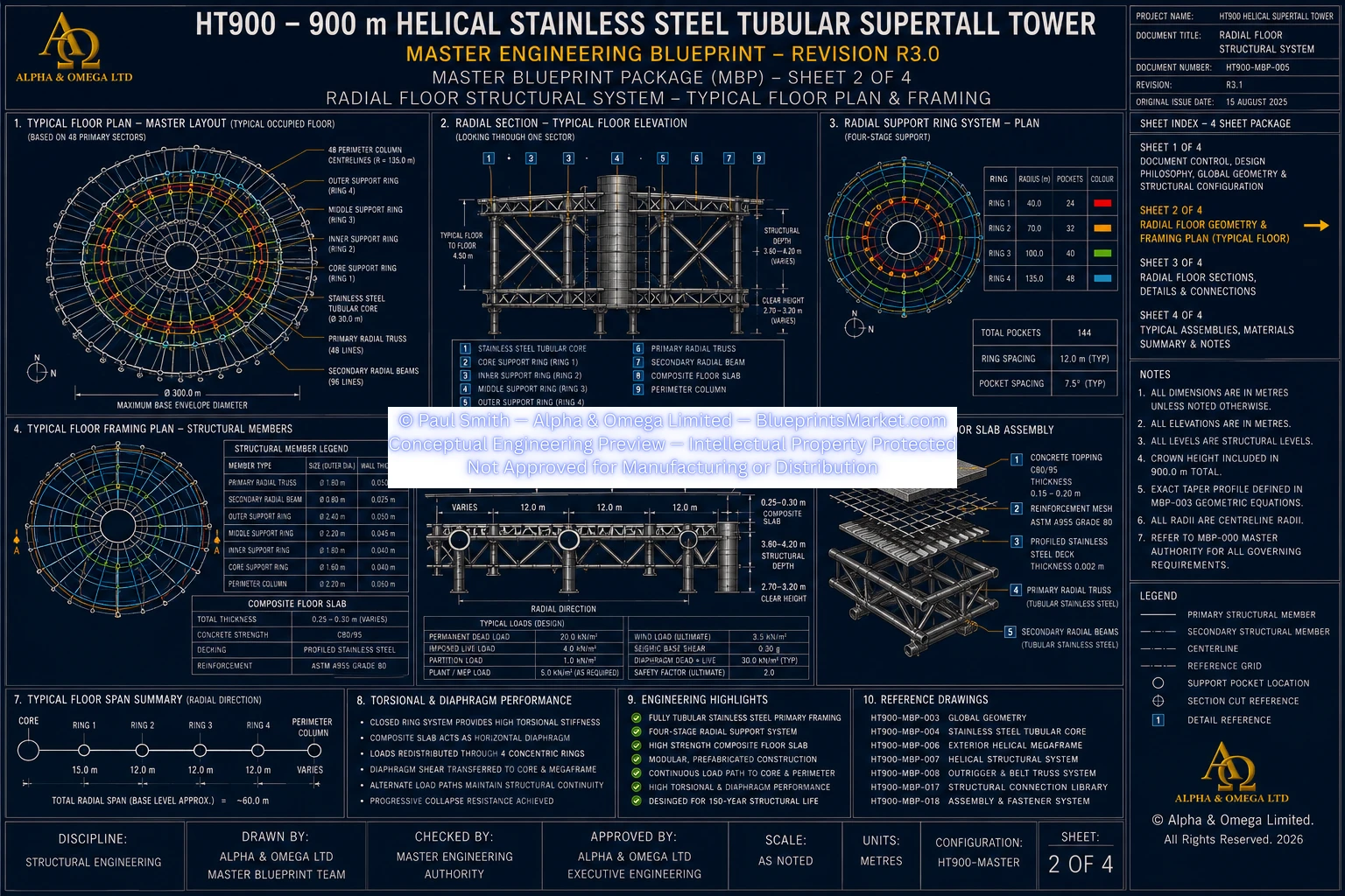
✔ HT900-MBP-005 — Radial Floor Structural System
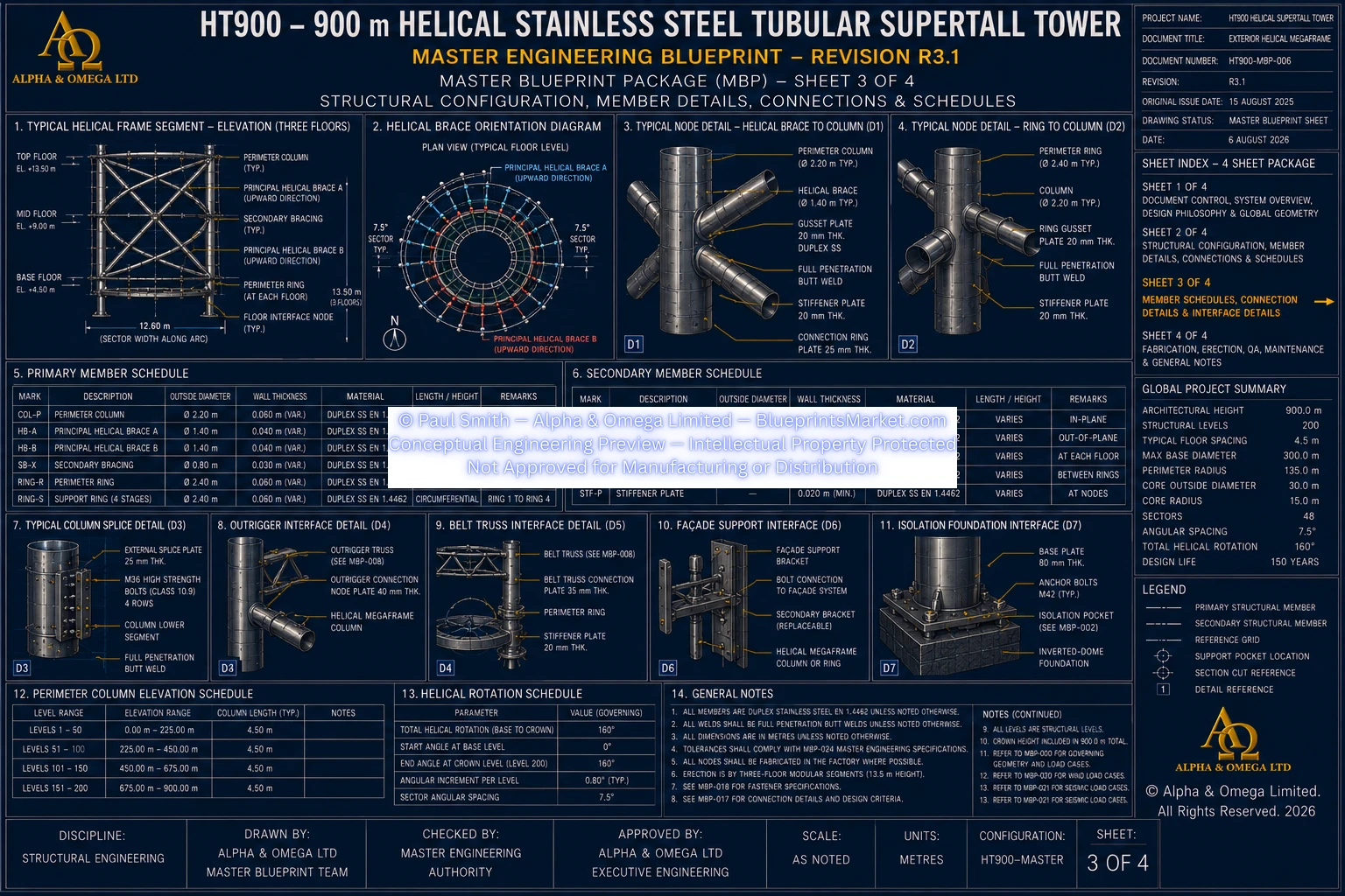
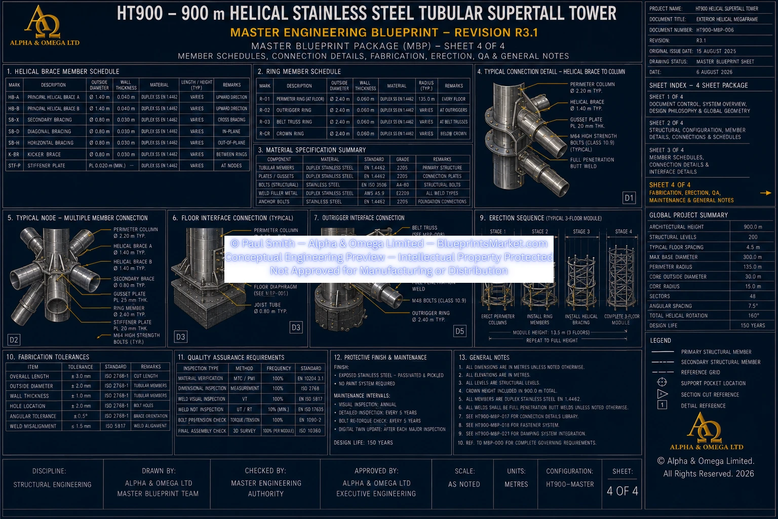
✔ HT900-MBP-006 — Exterior Helical Megaframe
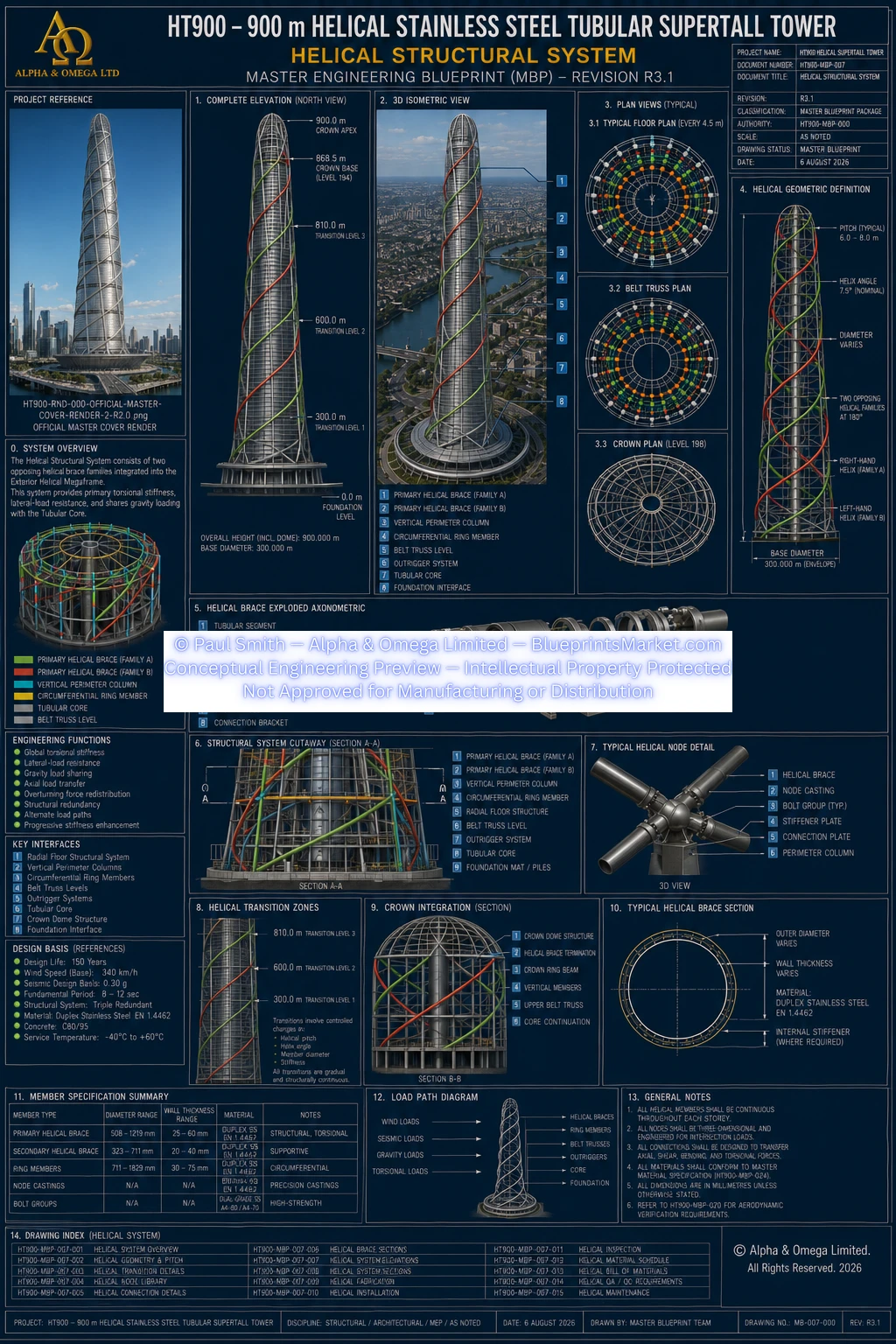
✔ HT900-MBP-007 — Helical Structural System
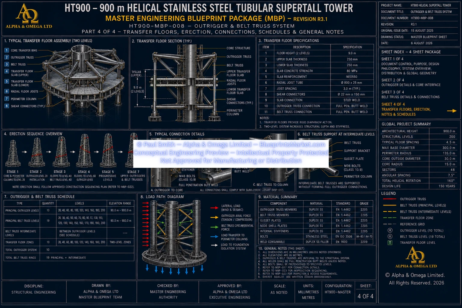
✔ HT900-MBP-008 — Outrigger & Belt-Truss System
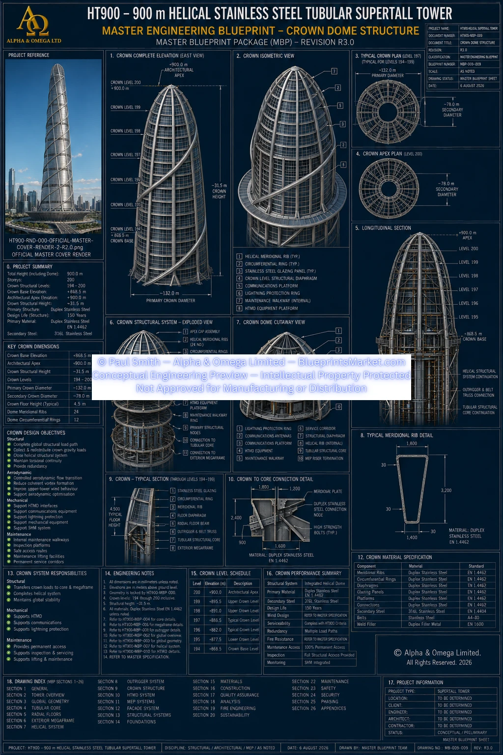
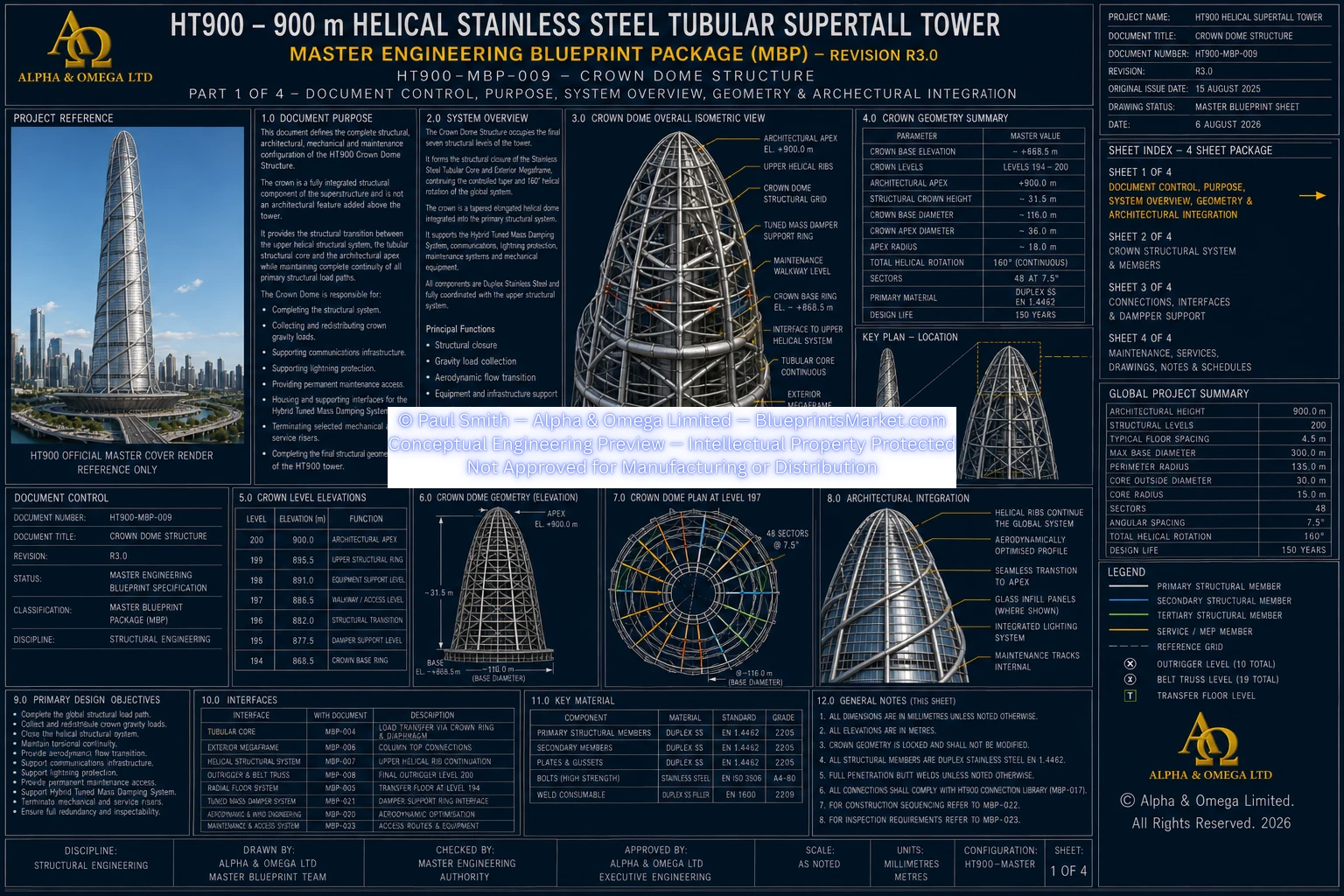
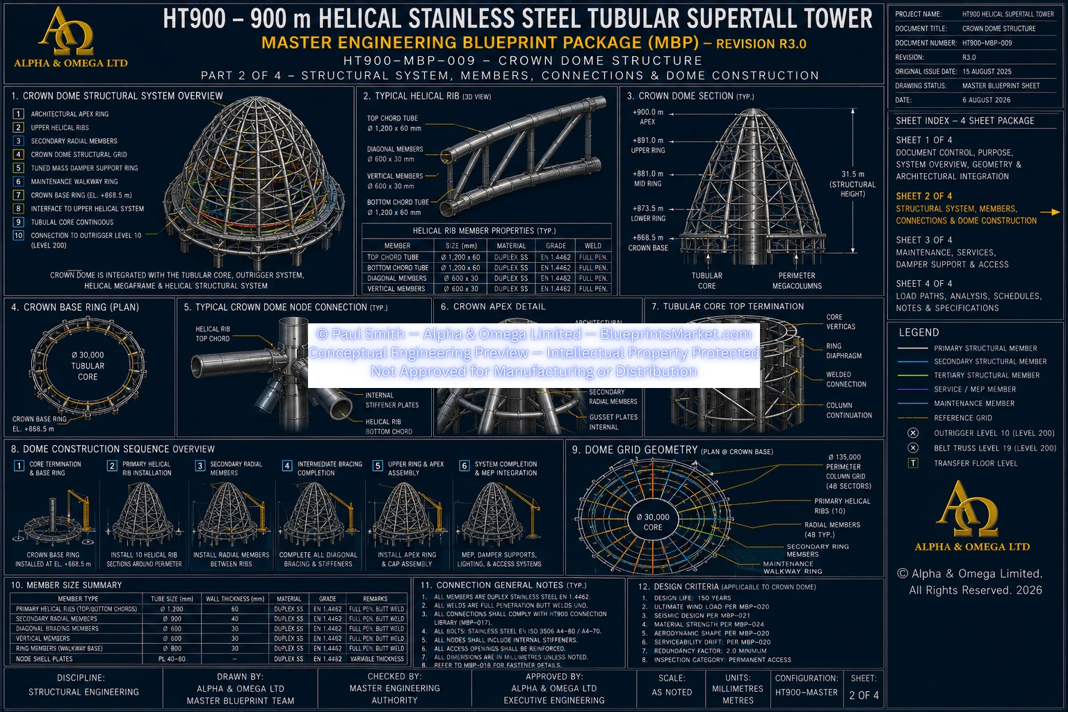
✔ HT900-MBP-009 — Crown Dome Structure
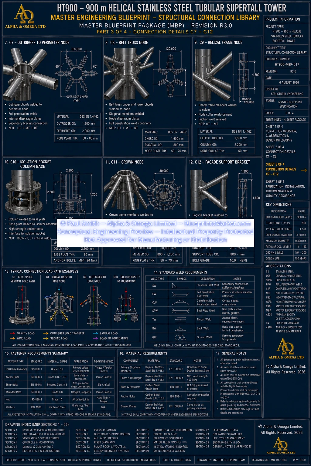
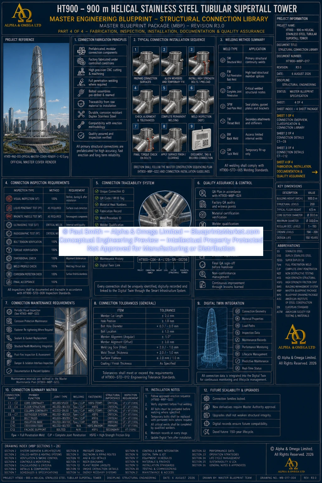
✔ HT900-MBP-017 — Structural Connection Library
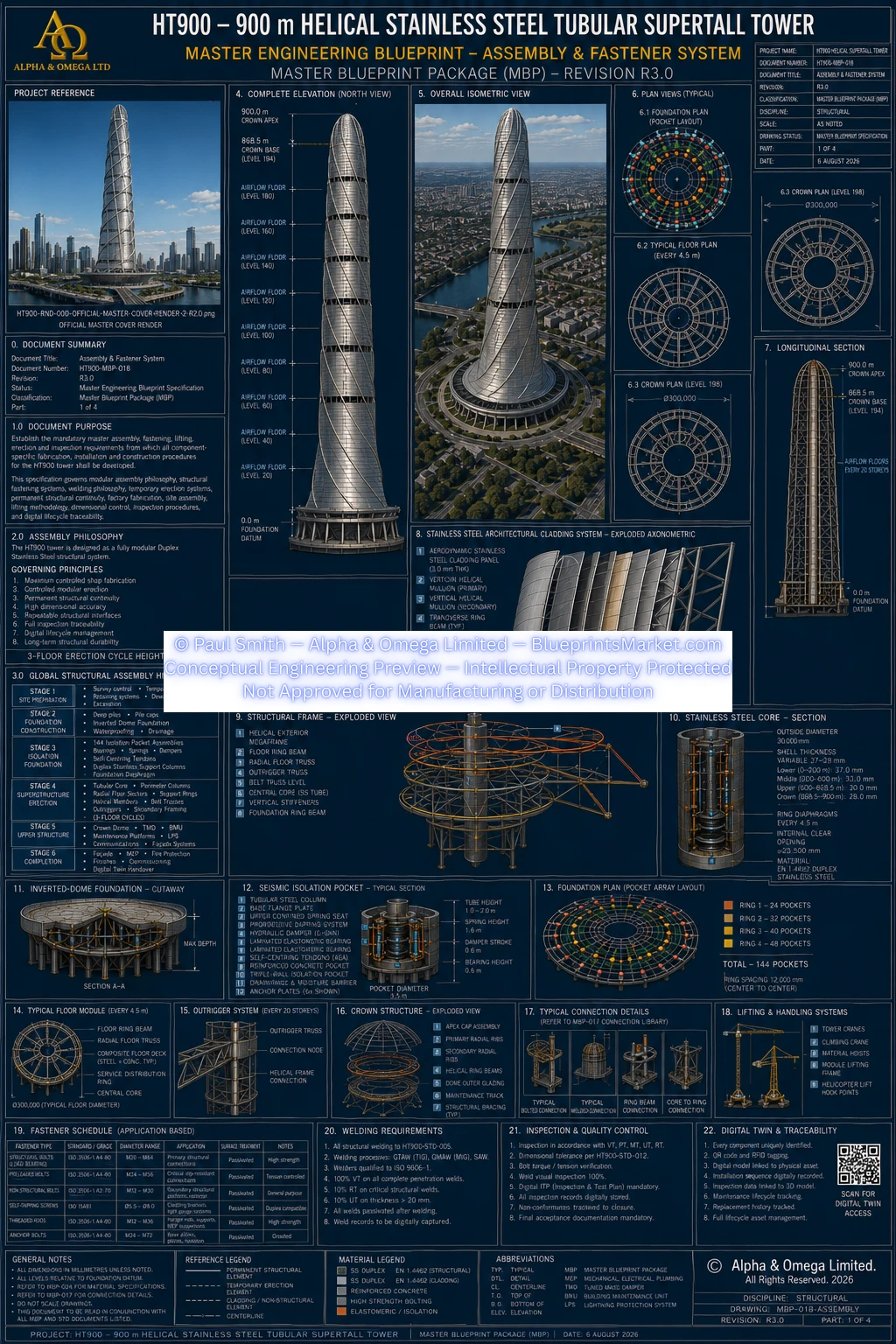
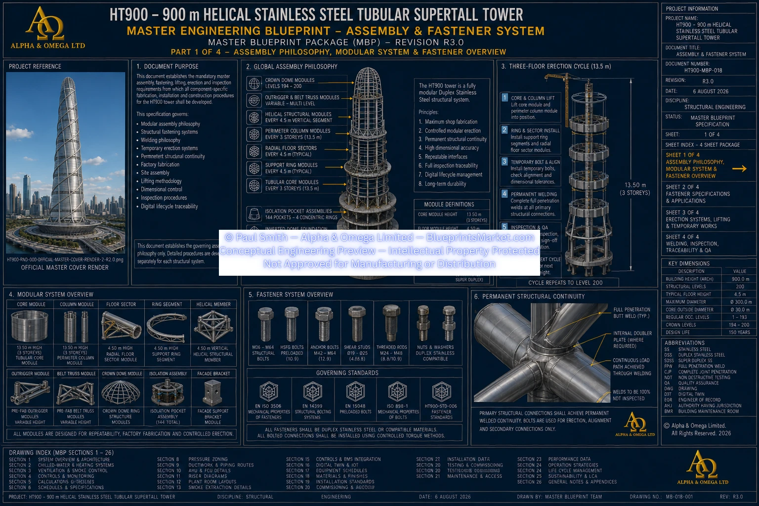
✔ HT900-MBP-018 — Assembly & Fastener System
✔ HT900-MBP-019 — Consolidated Master Parts Register and Bill of Materials
✔ HT900-MBP-020 — Aerodynamic & Wind Engineering
✔ HT900-MBP-021 — Tuned Mass Damping System
✔ HT900-MBP-022 — Construction Sequencing
✔ HT900-MBP-023 — Maintenance & Access System
✔ HT900-MBP-024 — Master Engineering Specifications
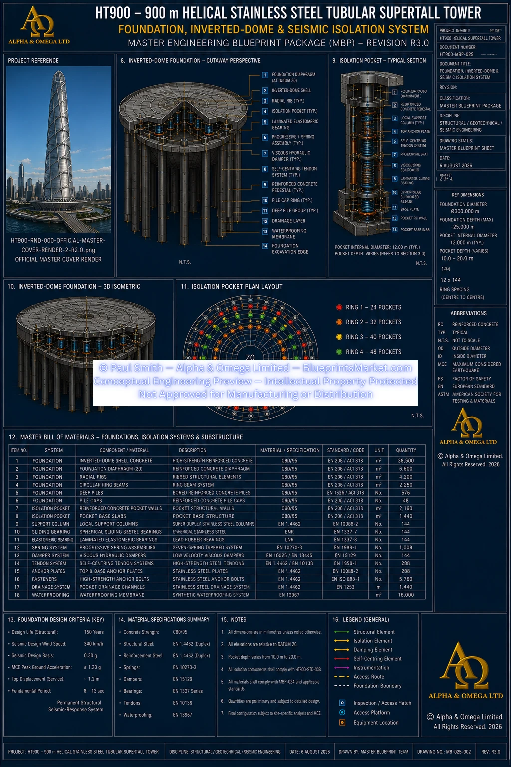
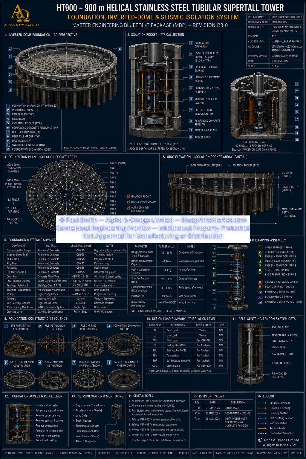
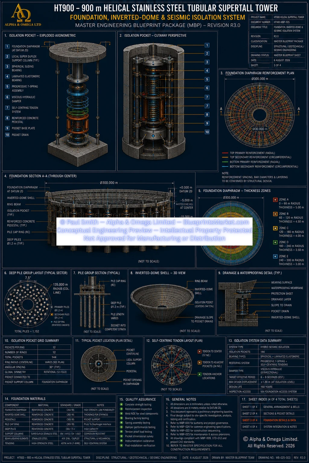
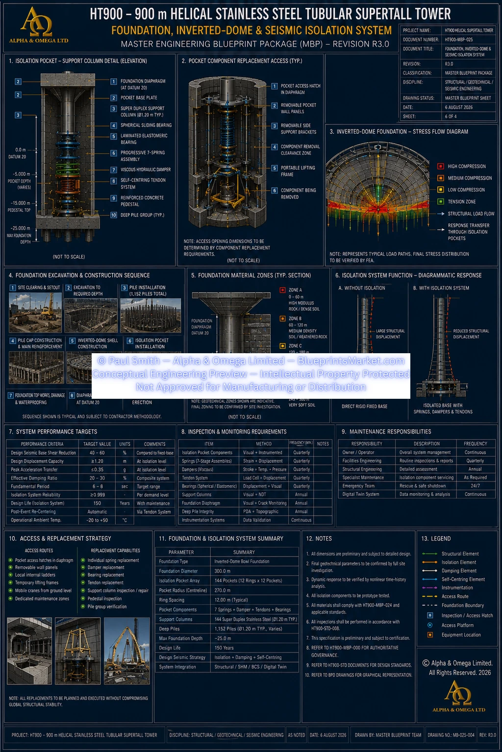
✔ HT900-MBP-025 — Foundation, Inverted-Dome & Seismic Isolation System
Together these document and blueprint families establish the conceptual
structural design philosophy, global geometry, structural-system
relationships, load-transfer philosophy, connection and assembly
requirements, construction sequencing, inspection provisions and
maintenance framework for the HT900 tower.
Foundation, Inverted-Dome & Seismic Isolation System
The HT900 foundation architecture integrates the tower's deep-foundation,
inverted-dome foundation and seismic-isolation concepts into a coordinated
structural support system for the 900 metre Helical Stainless-Steel Tubular
Supertall Tower.
The documented foundation concept combines a large-scale inverted concave
dome foundation, deep pile support system and distributed seismic-isolation
architecture to establish the primary interface between the tower
superstructure and its founding system.
The foundation and isolation architecture is documented within
HT900-MBP-025 — Foundation, Inverted-Dome & Seismic Isolation System.
Inverted Concave Dome Foundation
Principal conceptual foundation characteristics include:
✔ 300.0 metre maximum foundation diameter
✔ 150.0 metre maximum radius
✔ Maximum central depth of approximately 25 metres
✔ Inverted concave dome structural geometry
✔ Variable structural thickness
✔ Integrated structural support zones
✔ Interfaces with the seismic-isolation system
✔ Interfaces with the deep-foundation system
✔ Coordinated global structural load-transfer concept
The inverted-dome foundation forms the principal foundation platform
beneath the HT900 tower and provides the structural interface between
the superstructure, seismic-isolation assemblies and deep-foundation
system.
Deep Foundation System
The documented foundation architecture incorporates:
✔ Deep pile support system
✔ Pile-cap interfaces
✔ Foundation structural anchoring interfaces
✔ Isolation-pocket foundation interfaces
✔ Foundation drainage provisions
✔ Waterproofing provisions
✔ Inspection and maintenance provisions
✔ Foundation monitoring provisions
These systems form part of the coordinated HT900 foundation and
substructure architecture and provide the conceptual load-transfer
path between the tower, isolation system, foundation and competent
founding strata.
Seismic Isolation Pocket System
The HT900 seismic-isolation architecture incorporates distributed
isolation-pocket assemblies between the supported tower structure
and the foundation system.
The conceptual system combines multiple complementary isolation,
damping and self-centering mechanisms intended to manage structural
movement, dissipate seismic energy and reduce the transfer of
ground-motion effects into the superstructure.
Isolation Pocket Array
The documented isolation architecture includes:
✔ 144 isolation pocket assemblies
✔ Four concentric isolation-pocket rings
✔ Integrated structural support interfaces
✔ Triple-wall isolation-pocket construction
✔ Foundation and pile interfaces
✔ Drainage and waterproofing provisions
✔ Embedded monitoring and instrumentation provisions
Each isolation pocket forms a controlled structural interface within
the wider foundation and seismic-isolation system.
Progressive Energy Dissipation & Self-Centering System
The isolation-pocket architecture incorporates:
✔ Central progressive spring assembly
✔ Multiple outer spring assemblies
✔ Double-acting hydraulic damping units
✔ Laminated rubber-steel bearing system
✔ Spherical sliding bearing system
✔ Self-centering tendon assemblies
✔ Reinforced structural support interfaces
✔ Embedded structural monitoring sensors
These components operate as a coordinated conceptual isolation system
providing controlled displacement, energy dissipation, damping and
self-centering behaviour between the supported structure and foundation.
Integrated Structural Health Monitoring
The HT900 foundation and seismic-isolation architecture incorporates
Structural Health Monitoring provisions as part of the wider tower
monitoring, control, inspection and maintenance philosophy.
Documented monitoring provisions include:
✔ Strain monitoring
✔ Displacement monitoring
✔ Acceleration monitoring
✔ Pressure monitoring
✔ Temperature monitoring
✔ Vibration monitoring
✔ Structural movement monitoring
✔ Sensor inspection and replacement access
The monitoring architecture supports structural condition assessment,
inspection planning, maintenance activities and long-term performance
monitoring throughout the tower's intended lifecycle.
Detailed sensor quantities, locations, installation requirements,
monitoring logic and component specifications are contained within
the applicable HT900 technical documentation.
Aerodynamic & Wind Engineering
The HT900 incorporates an integrated aerodynamic and wind-engineering
philosophy coordinated with the tower's helical geometry, Exterior
Helical Megaframe, Helical Structural System, Outrigger & Belt-Truss
System and global structural architecture.
The aerodynamic and wind-engineering concepts are documented within
HT900-MBP-020 — Aerodynamic & Wind Engineering.
The tower's helical architectural and structural form is intended to
manage wind interaction, limit adverse aerodynamic effects and support
the overall lateral and dynamic performance strategy of the
900 metre supertall structure.
Helical Aerodynamic Design Philosophy
The documented aerodynamic architecture addresses:
✔ 160° total helical tower rotation
✔ Wind interaction with the tower's helical geometry
✔ Vortex-shedding mitigation philosophy
✔ Dynamic structural-response considerations
✔ Lateral-motion control strategy
✔ Torsional-response considerations
✔ Occupant-comfort objectives
✔ Coordination with the primary structural systems
Wind Engineering Integration
The wind-engineering architecture interfaces with:
✔ Global tower geometry
✔ Exterior Helical Megaframe
✔ Helical Structural System
✔ Stainless Steel Tubular Core
✔ Radial Floor Structural System
✔ Outrigger & Belt-Truss System
✔ Crown Dome Structure
✔ Tuned Mass Damping System
✔ Structural Health Monitoring provisions
✔ Building envelope interfaces
These coordinated systems establish the conceptual framework for
evaluating wind actions, structural response, dynamic behaviour,
torsional effects and occupant-comfort performance during subsequent
project-specific professional engineering development.
Integrated Building Systems Architecture
The HT900 Master Blueprint Package integrates the principal building-service,
vertical transportation, environmental-control, electrical, control,
smart-infrastructure and life-safety systems within the coordinated
conceptual architecture of the 900 metre Helical Stainless-Steel Tubular
Supertall Tower.
The documented building systems are coordinated with the tower's
structural geometry, floor configuration, vertical service zones,
Stainless Steel Tubular Core, Radial Floor Structural System,
Exterior Helical Megaframe and associated building-system interfaces.
The package establishes common system relationships, component
identification, interface requirements, monitoring provisions,
inspection requirements and maintenance concepts across the
documented building systems.
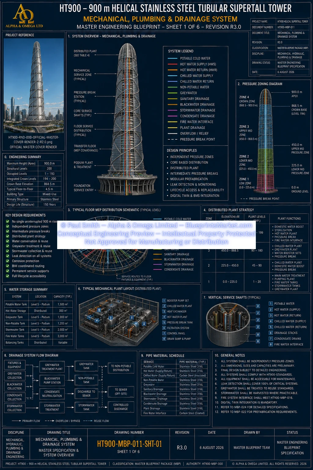
Mechanical, Plumbing, Electrical & Environmental Systems
The principal building-services architecture is documented across
the dedicated HT900 Master Blueprint Package system families:
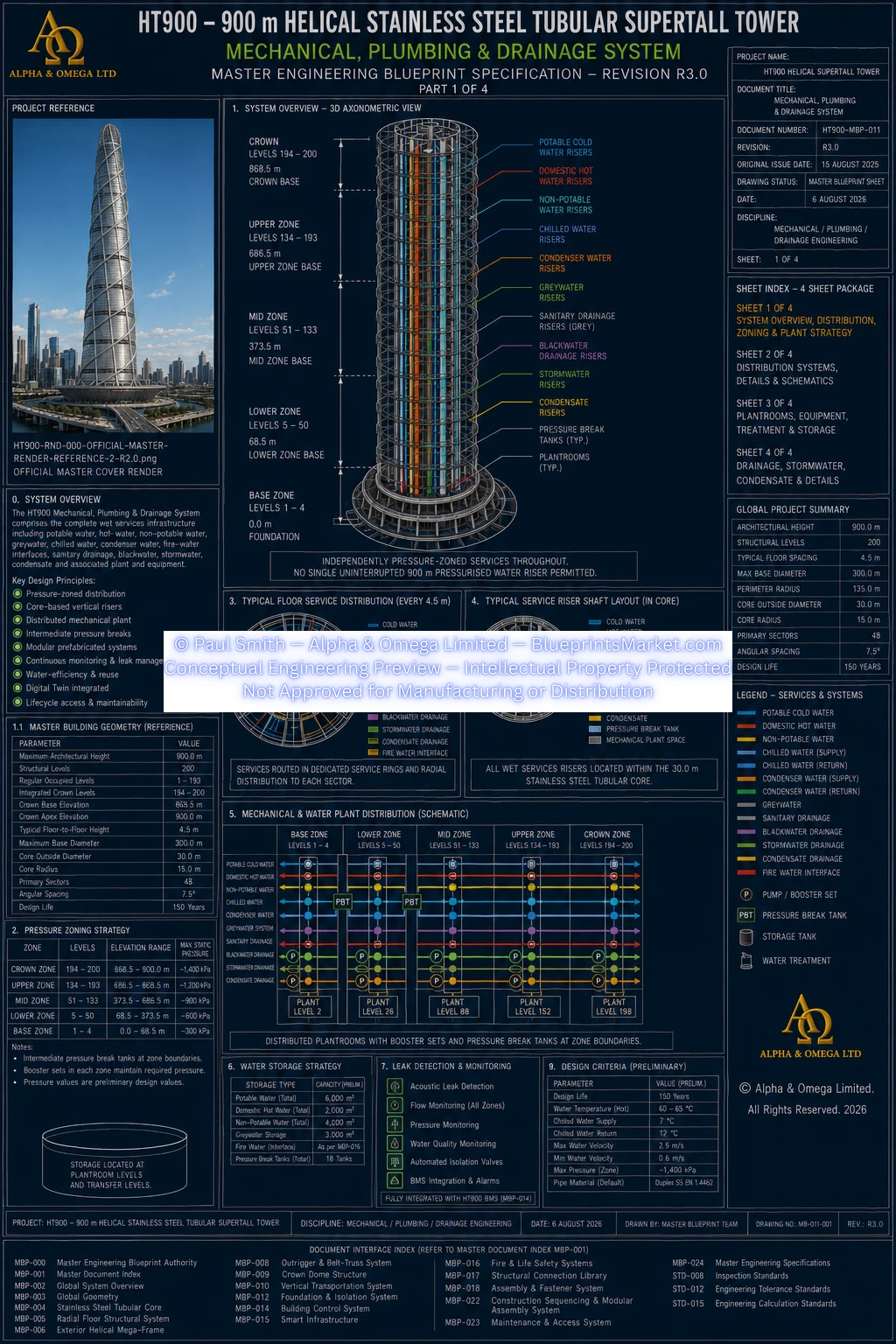
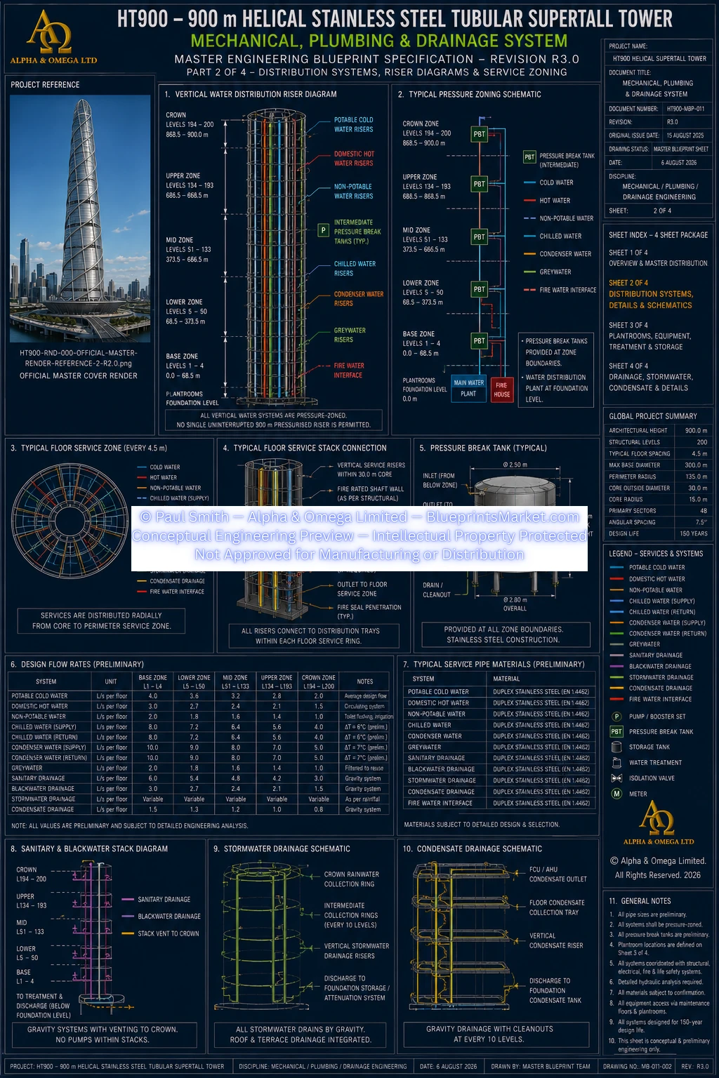
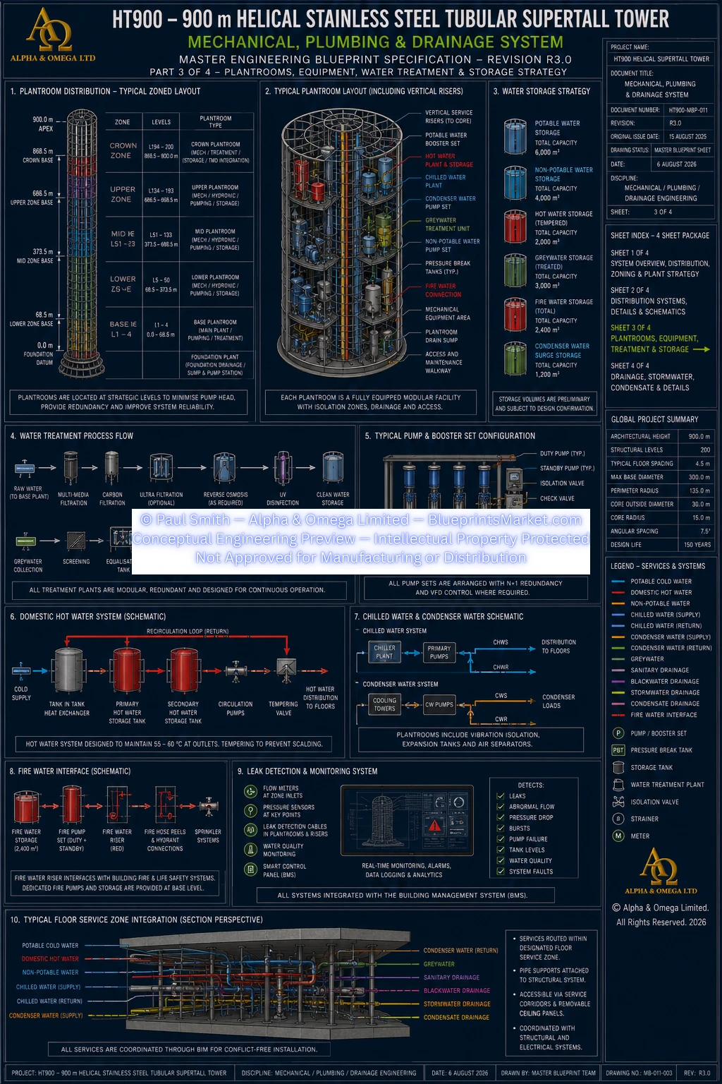
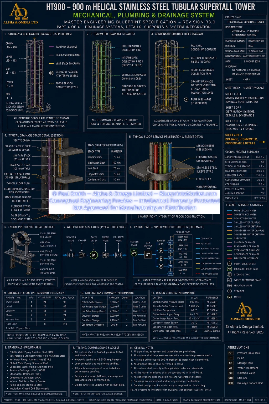
✔ HT900-MBP-011 — Mechanical, Plumbing & Drainage System
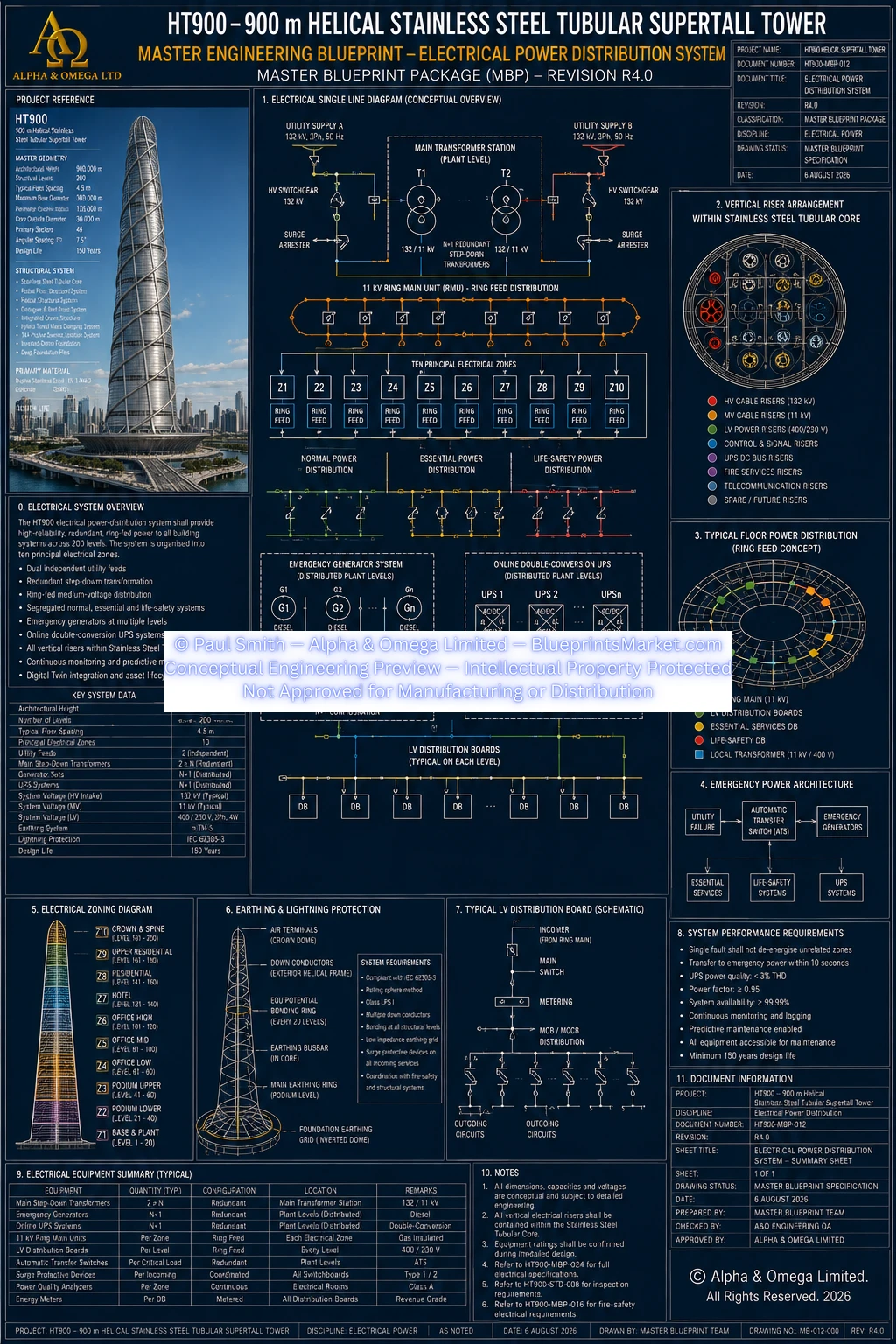
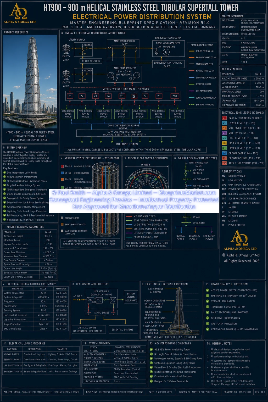
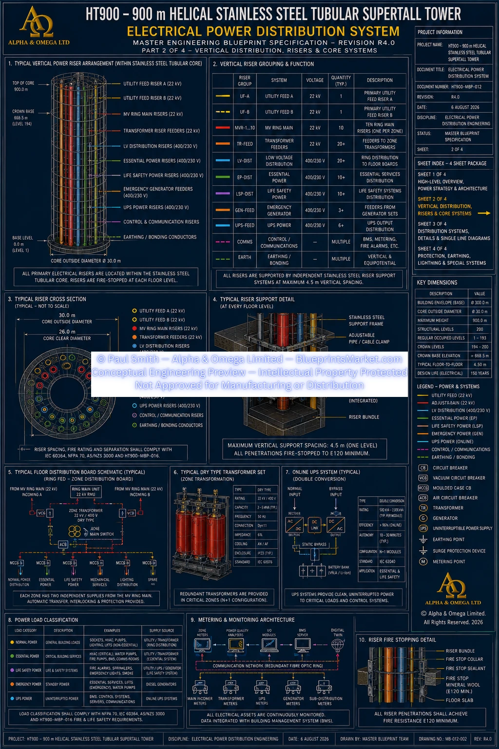
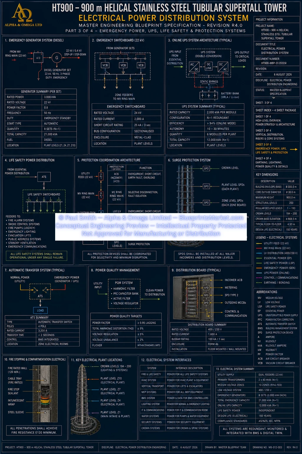
✔ HT900-MBP-012 — Electrical Power Distribution System
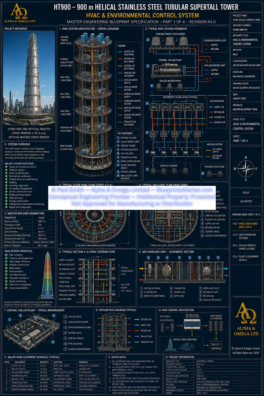
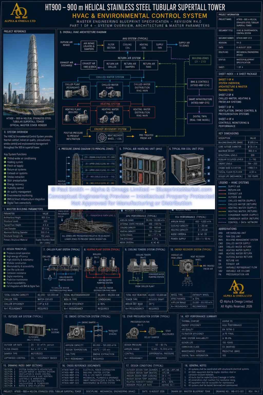
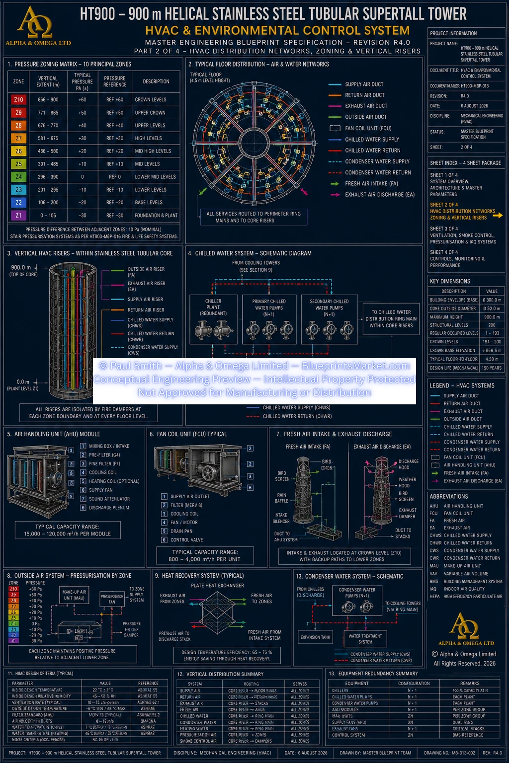
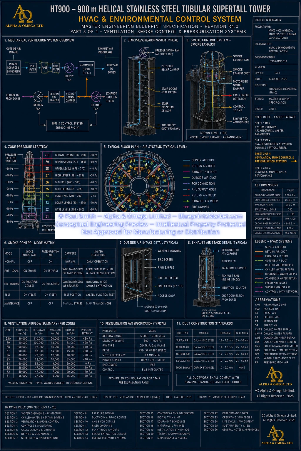
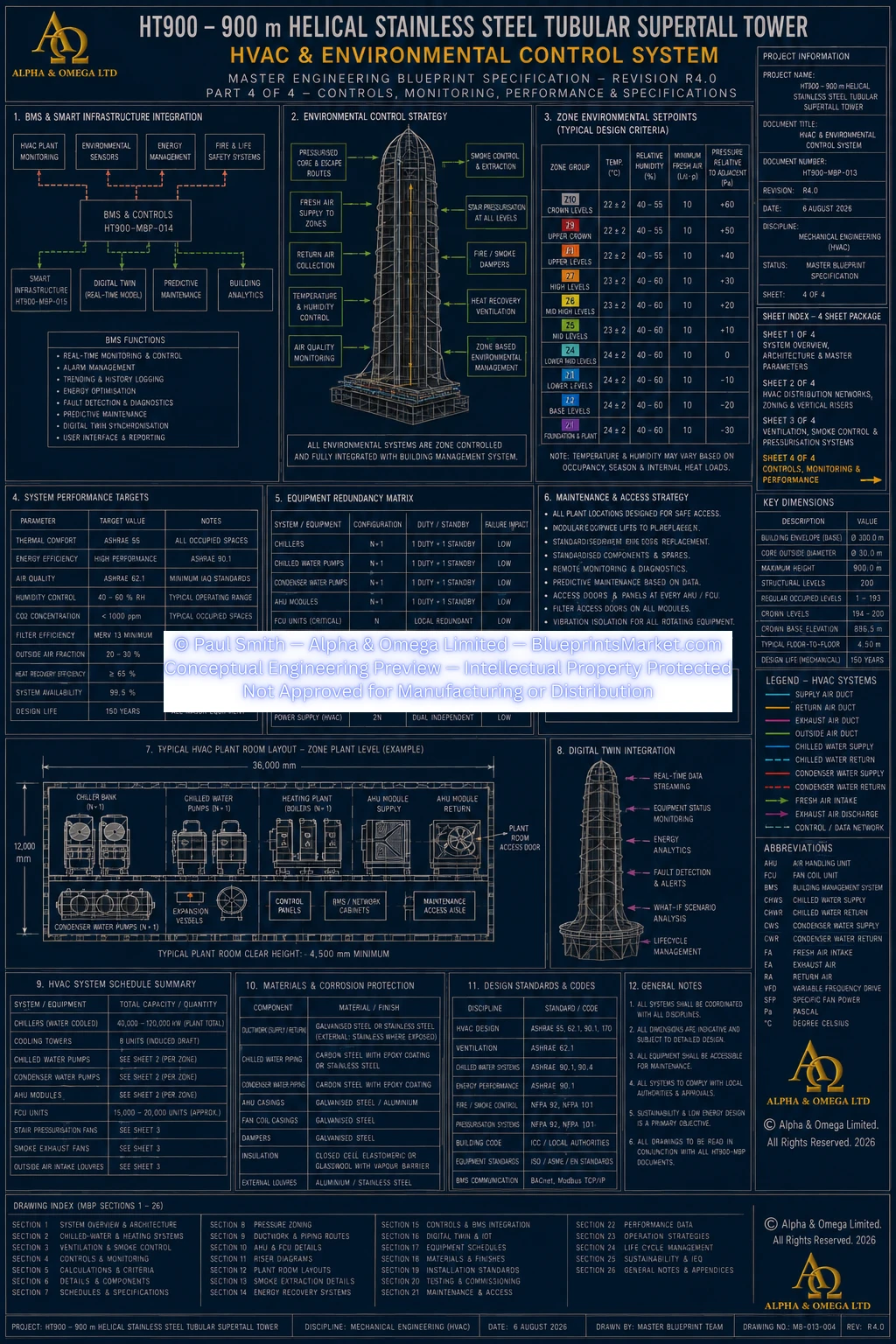
✔ HT900-MBP-013 — HVAC & Environmental Control System
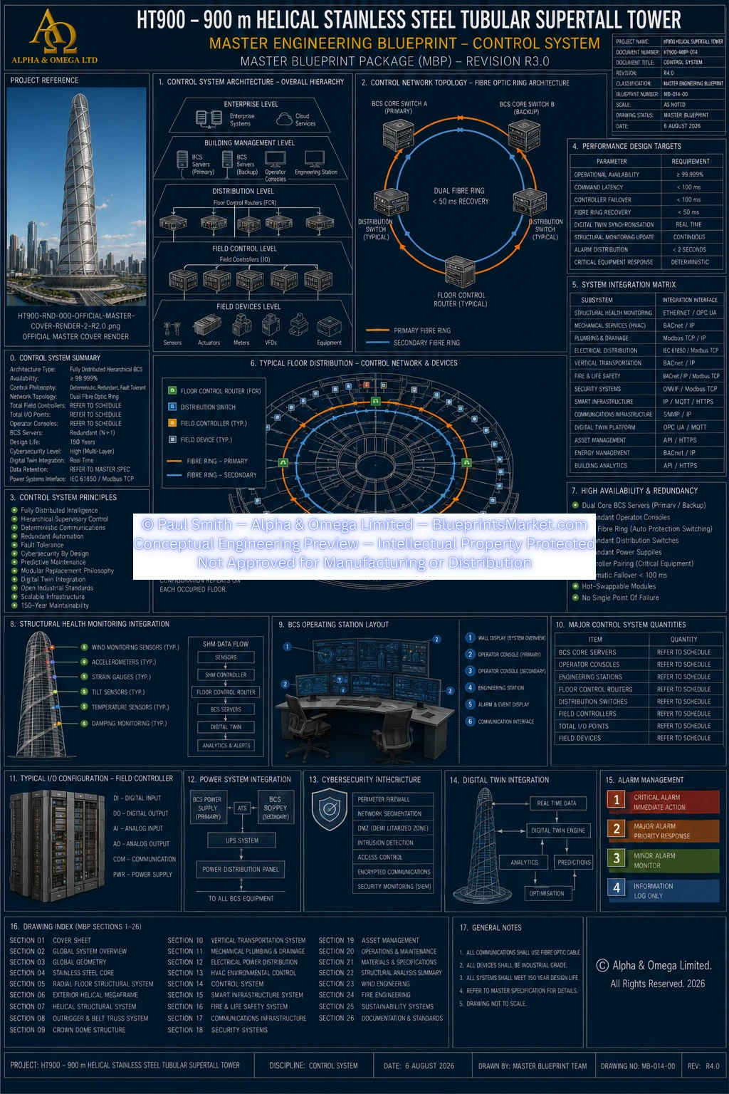
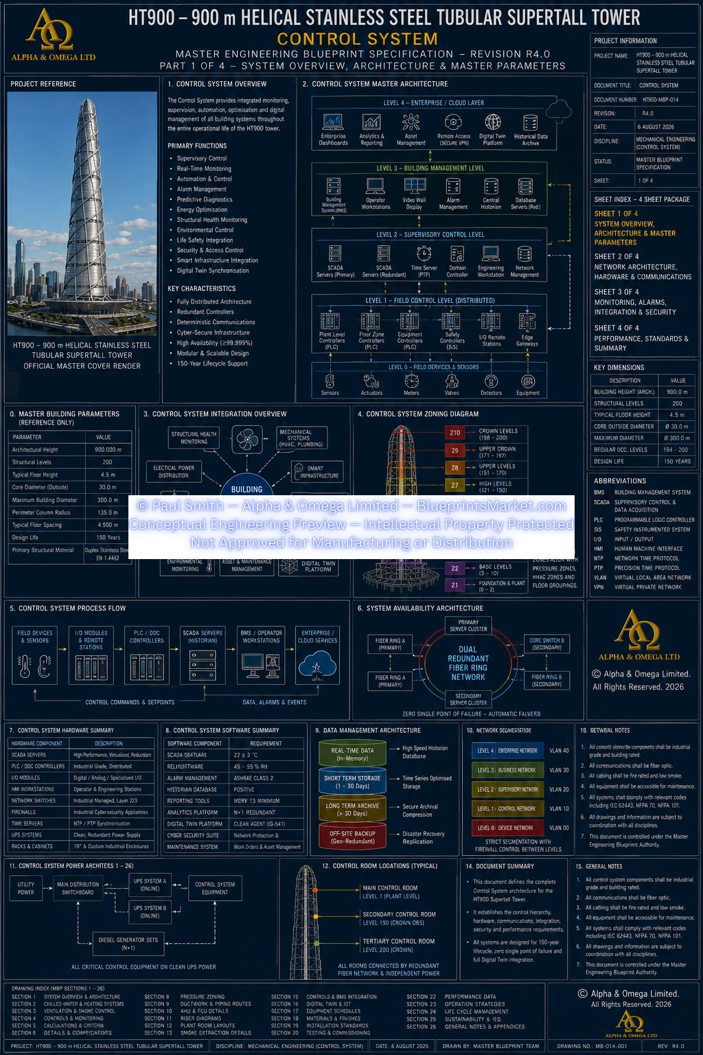
✔ HT900-MBP-014 — Control System
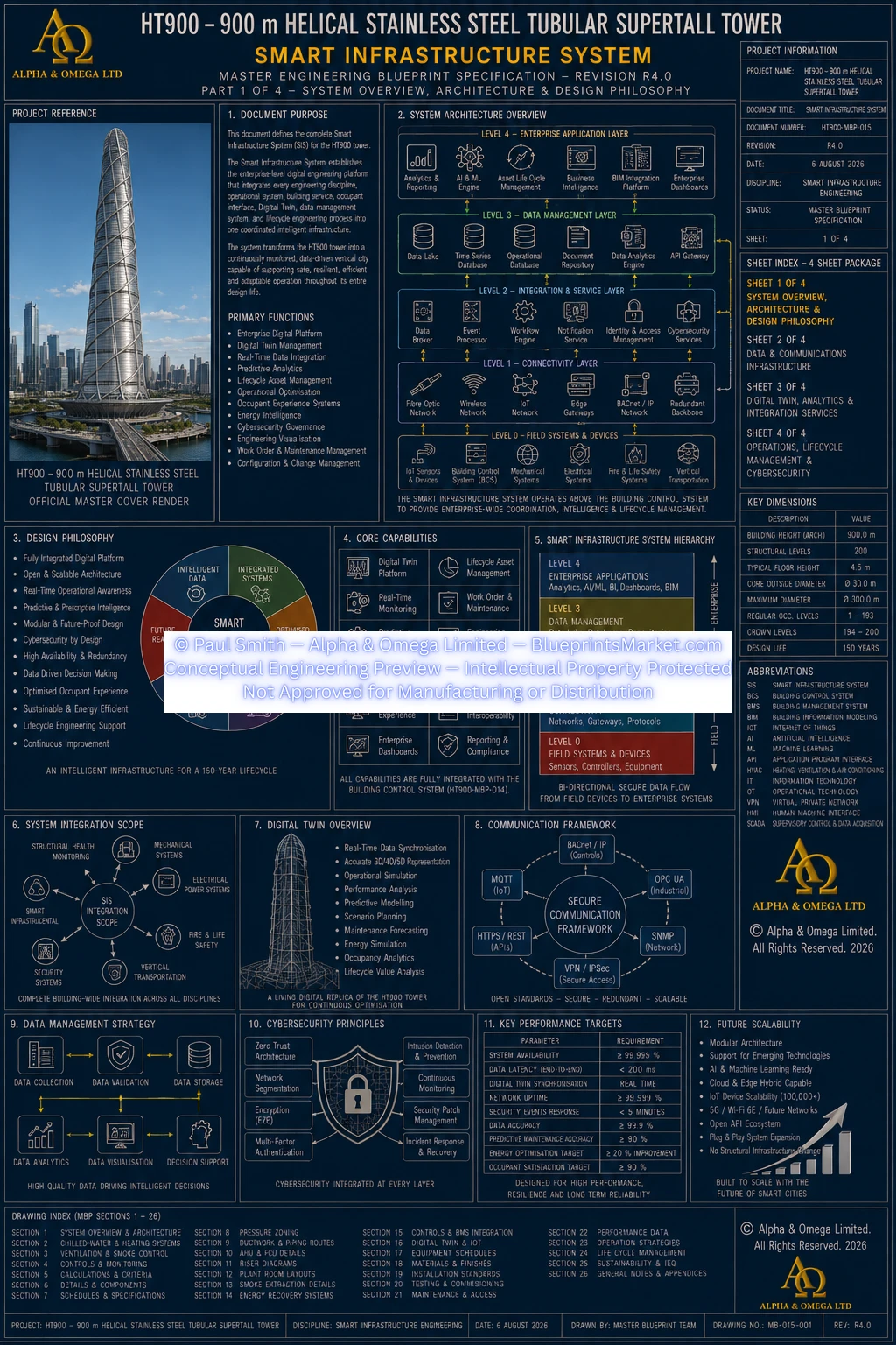
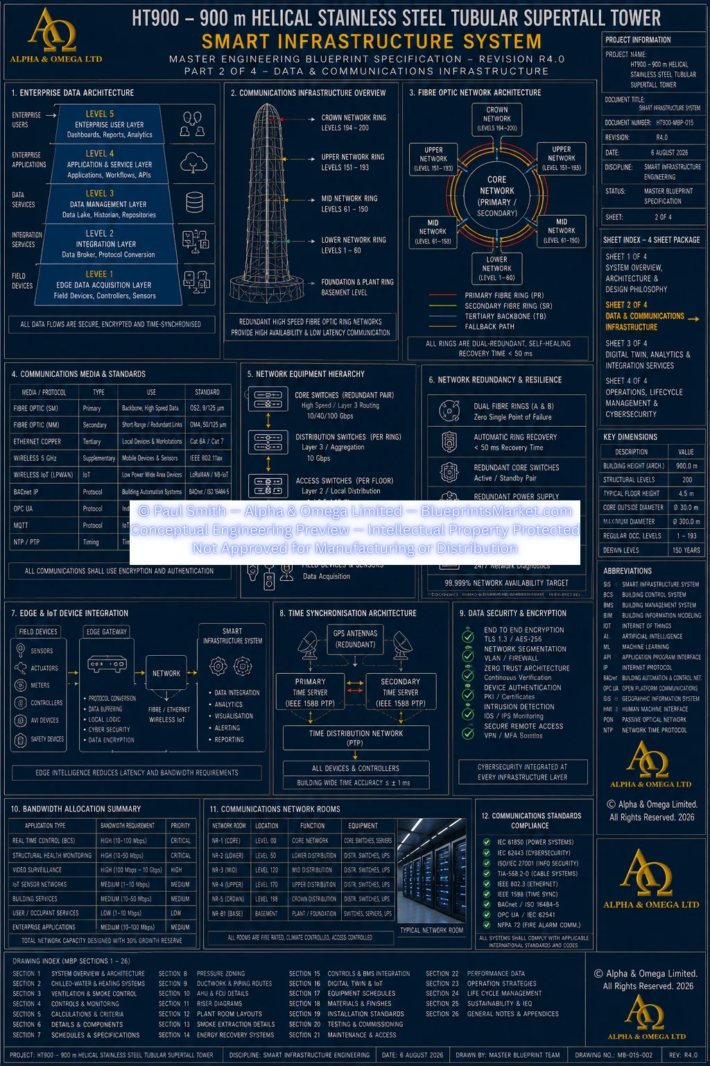
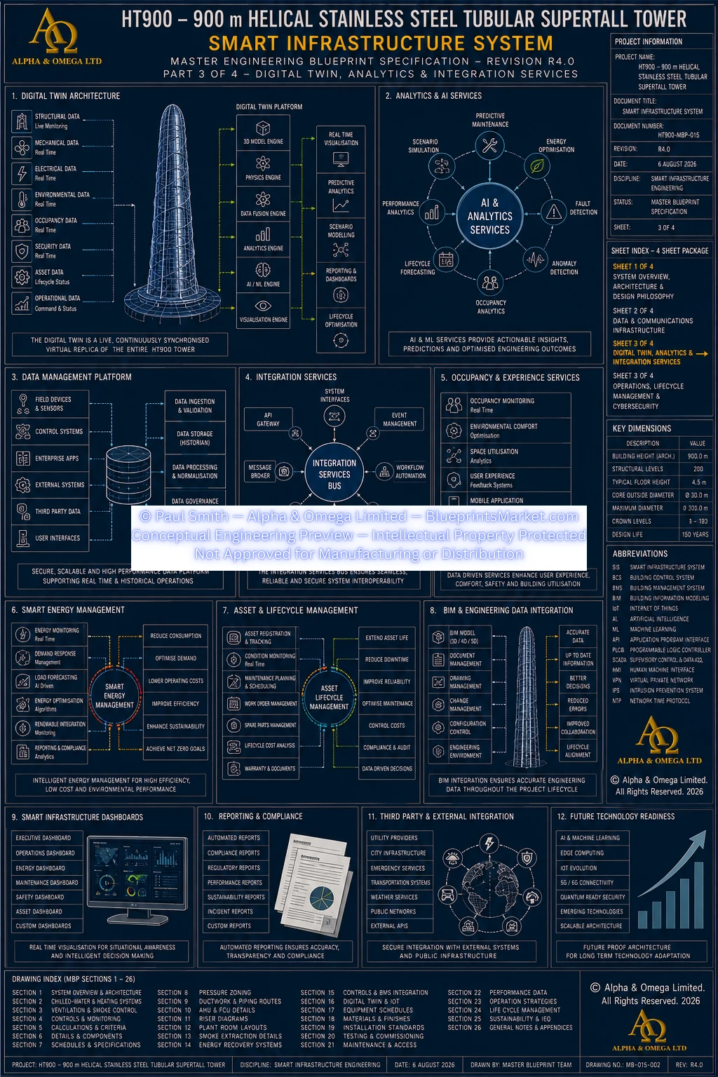
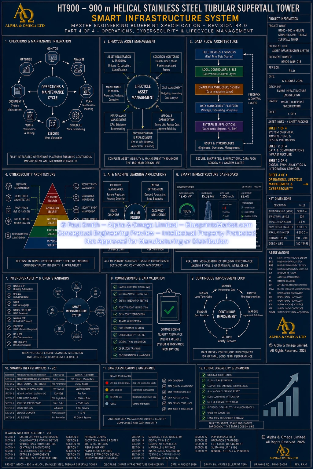
✔ HT900-MBP-015 — Smart Infrastructure System
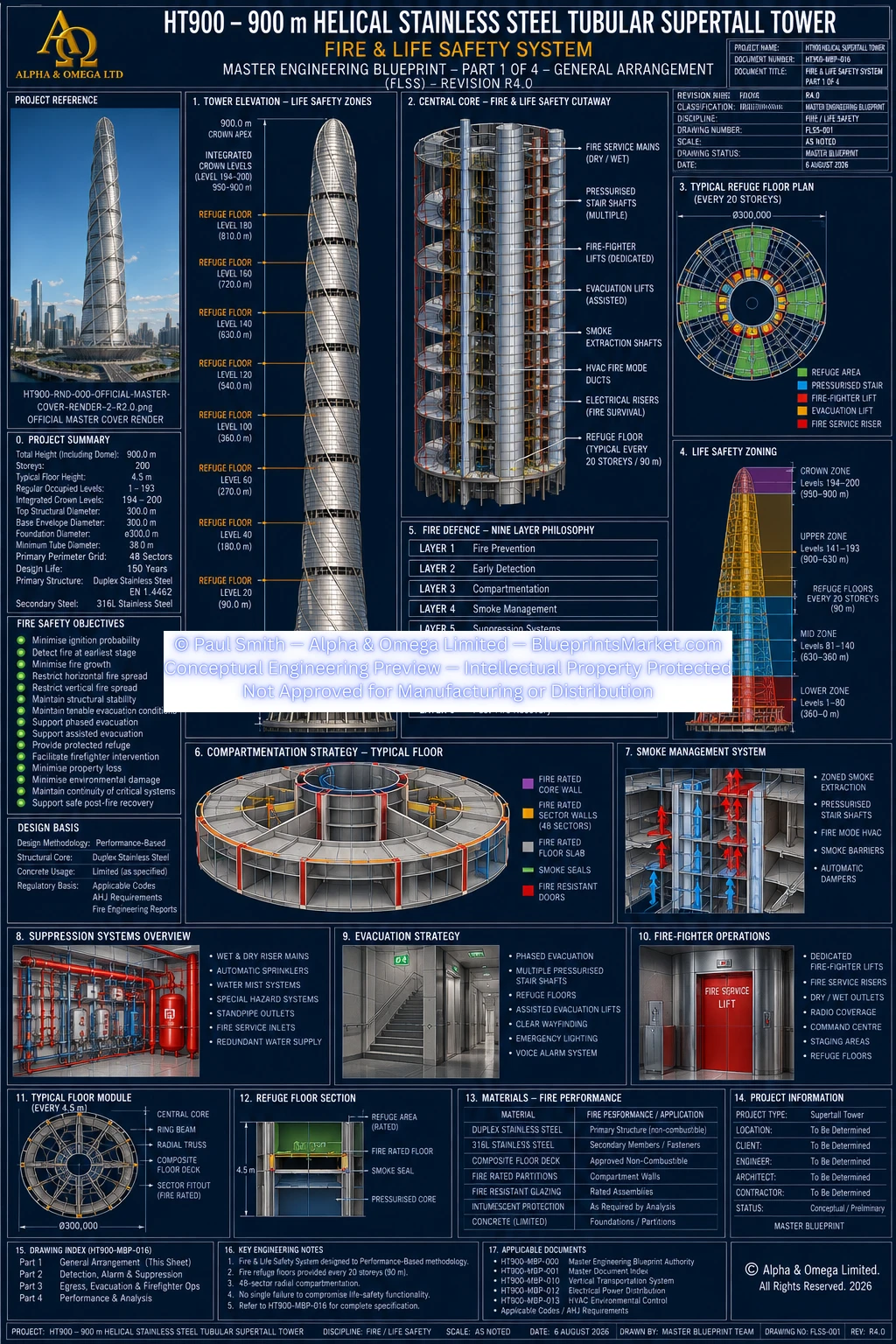
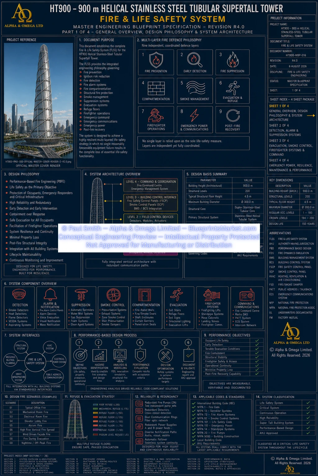
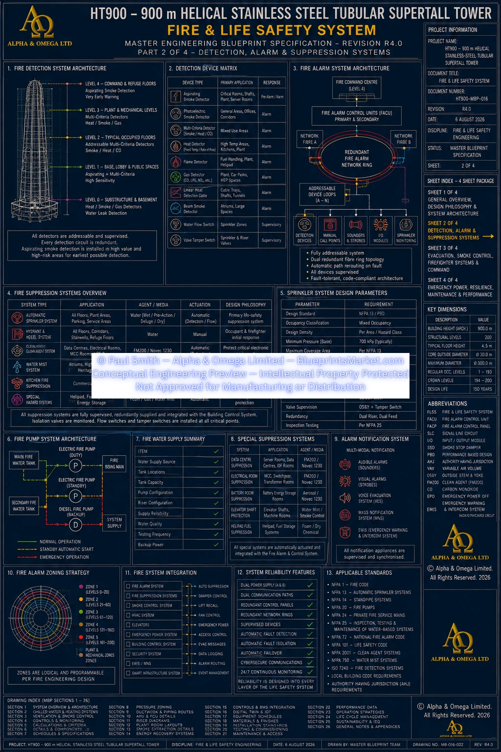
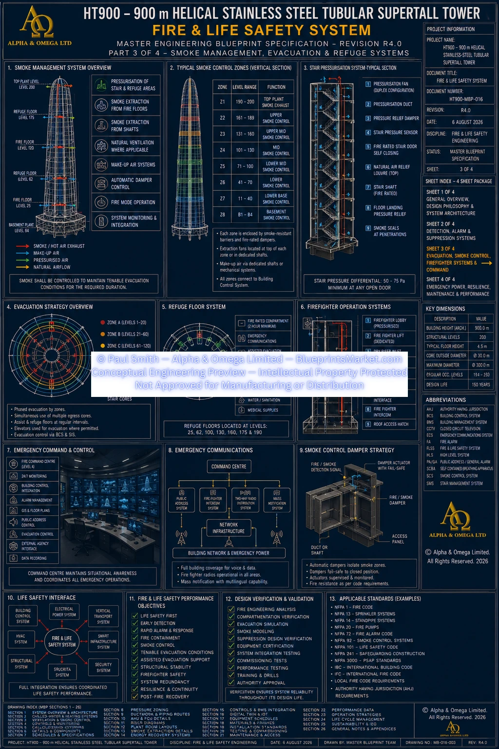
✔ HT900-MBP-016 — Fire & Life Safety System
Together these systems establish the conceptual building-services
framework for mechanical distribution, plumbing and drainage,
electrical power distribution, environmental control, system
monitoring, intelligent infrastructure and life-safety integration.
Vertical Transportation System
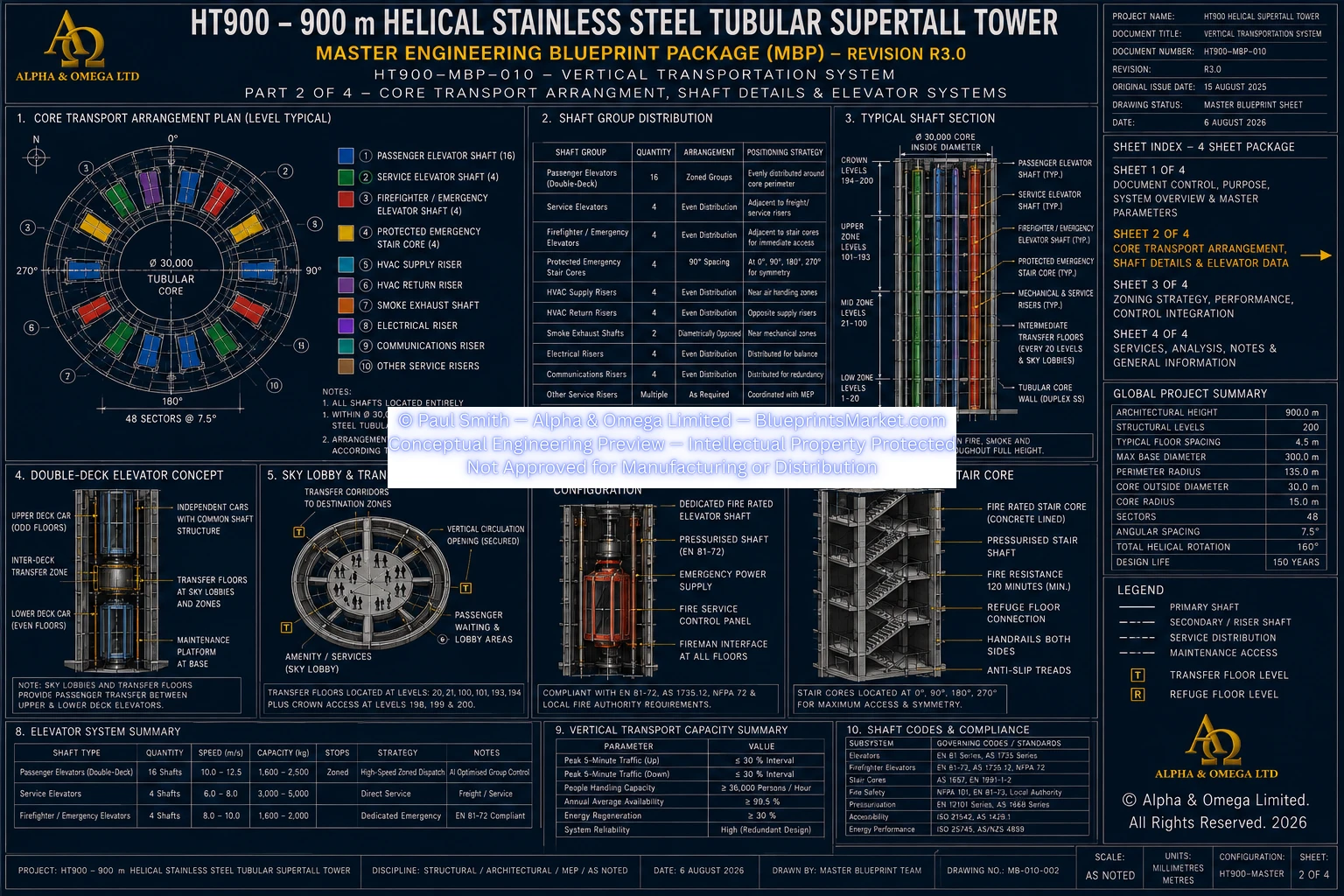
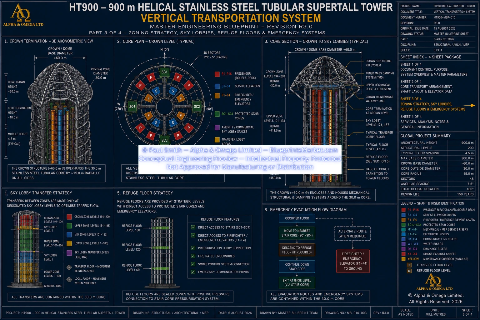
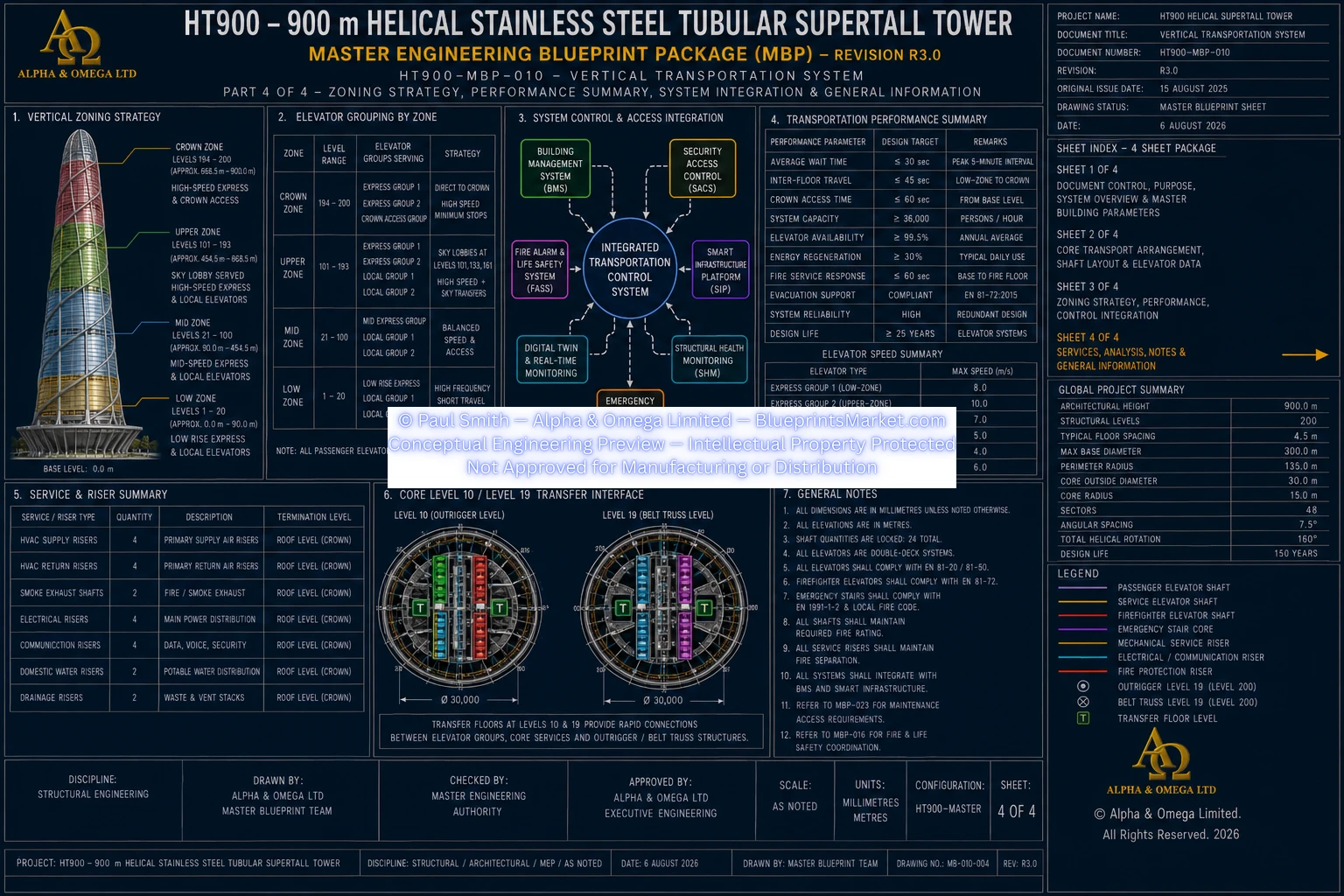
HT900-MBP-010 — Vertical Transportation System documents the
conceptual vertical-movement architecture for the 200-level tower.
The documented system addresses:
✔ Lift and elevator system architecture
✔ Vertical transportation zoning
✔ Passenger movement concepts
✔ Service and operational transportation
✔ Emergency and life-safety interfaces
✔ Vertical circulation interfaces
✔ Structural-core integration
✔ Electrical-system interfaces
✔ Control-system interfaces
✔ Monitoring provisions
✔ Inspection and maintenance access
The Vertical Transportation System is coordinated with the
Stainless Steel Tubular Core and the wider electrical, control,
smart-infrastructure, fire and life-safety architecture.
Control Systems & Smart Infrastructure
The HT900 conceptual architecture extends beyond the primary
structural and building-services systems through coordinated
control, monitoring, communications, instrumentation and
smart-infrastructure concepts.
These functions are principally documented through
HT900-MBP-014 — Control System and
HT900-MBP-015 — Smart Infrastructure System, with interfaces
to the mechanical, electrical, HVAC, vertical transportation,
fire and life-safety, structural-monitoring and maintenance systems.
Smart Infrastructure Architecture
The documented smart-infrastructure architecture addresses
the coordinated information and monitoring requirements of
the tower's principal systems.
Conceptual provisions include:
✔ Building communications infrastructure
✔ System data communications
✔ Monitoring-system connectivity
✔ Sensor and instrumentation interfaces
✔ Building-system information exchange
✔ Structural monitoring interfaces
✔ Electrical-system monitoring interfaces
✔ Mechanical and environmental monitoring interfaces
✔ Fire and life-safety interfaces
✔ Vertical transportation interfaces
✔ Component identification and traceability concepts
✔ Inspection and maintenance information interfaces
Integrated Control Architecture
The HT900 Control System establishes the conceptual coordination
framework for monitoring and controlling the tower's integrated
building systems.
The documented architecture includes:
✔ Building-system control concepts
✔ Distributed monitoring architecture
✔ Sensor and instrumentation integration
✔ Mechanical-system control interfaces
✔ Electrical-system monitoring interfaces
✔ HVAC and environmental-control interfaces
✔ Vertical transportation control interfaces
✔ Fire and life-safety interfaces
✔ Smart-infrastructure interfaces
✔ Alarm and system-status monitoring concepts
✔ Operational monitoring concepts
✔ Maintenance and diagnostic information interfaces
Electrical Power & Environmental Control Architecture
The HT900 Master Blueprint Package coordinates the tower's electrical
power and environmental-control concepts through
HT900-MBP-012 — Electrical Power Distribution System and
HT900-MBP-013 — HVAC & Environmental Control System.
These systems establish the conceptual framework for distributing
electrical power throughout the tower and maintaining coordinated
environmental-control services across the 200 structural levels.
Electrical Power Distribution
The documented electrical architecture addresses:
✔ Electrical power distribution
✔ Vertical electrical distribution
✔ Floor-level electrical distribution
✔ Building-services power interfaces
✔ Vertical transportation power interfaces
✔ Mechanical and HVAC power interfaces
✔ Control-system interfaces
✔ Fire and life-safety electrical interfaces
✔ Monitoring and instrumentation interfaces
✔ Maintenance and inspection provisions
HVAC & Environmental Control
The documented environmental-control architecture addresses:
✔ HVAC system architecture
✔ Air-distribution concepts
✔ Environmental-control zoning
✔ Mechanical-system interfaces
✔ Electrical-system interfaces
✔ Control and monitoring interfaces
✔ Sensor and instrumentation integration
✔ Environmental monitoring concepts
✔ Maintenance and inspection provisions
✔ Coordination with the tower's vertical service architecture
Materials, Fabrication & Lifecycle Engineering Philosophy
Material, fabrication, assembly, inspection and lifecycle requirements
within the HT900 architecture are distributed across the applicable
Master Blueprint Package documents rather than being defined by a
separate MAT-1400 package.
The documented engineering philosophy prioritises structural
performance, corrosion resistance, fabrication quality,
inspectability, maintainability and long-term lifecycle management.
Material & Fabrication Systems
Documented material and fabrication concepts include:
✔ Stainless-steel tubular structural systems
✔ EN 1.4462 Duplex Stainless Steel where specified
✔ Super Duplex Stainless Steel where specifically required
✔ High-strength structural connection components
✔ Corrosion-resistant material selection
✔ Welded structural assemblies
✔ Mechanically fastened structural assemblies
✔ Modular fabrication concepts
✔ Factory fabrication and inspection requirements
✔ Surface treatment and passivation requirements where specified
Engineering Control & Lifecycle Provisions
The HT900 documentation establishes conceptual provisions for:
✔ Material identification and certification
✔ Component identification and traceability
✔ Structural Connection Library requirements
✔ Assembly & Fastener System requirements
✔ Fabrication inspection
✔ Non-Destructive Testing requirements
✔ Installation and erection inspection
✔ Structural Health Monitoring provisions
✔ Permanent maintenance access
✔ Long-term inspection planning
✔ Maintenance-record philosophy
✔ Structural condition monitoring
✔ Controlled document and revision relationships
Licensing Options
The HT900 Helical Stainless-Steel Tubular Supertall Tower Master Blueprint Package is available under three licensing tiers designed for different levels of usage. Each license grants specific rights while all intellectual property remains exclusively owned by Alpha & Omega Limited.
Digital Edition
• Complete HT900 conceptual blueprint package
• High-resolution PNG conceptual engineering blueprint files
• DOCX technical documentation
• Master system and engineering documentation
• Personal study & research
• Educational reference
• Private non-commercial use only
Construction rights are NOT included.
Commercial License
Includes everything in the Digital Edition plus:
• Commercial media usage
• Films & documentaries
• Books & publications
• Concept art
• World-building
• Commercial research projects
Construction rights are NOT included.
Enterprise License
Includes the complete HT900 conceptual blueprint and
technical documentation package together with:
• Engineering firm usage
• Architectural studio usage
• Internal R&D usage
• Project feasibility studies
• Design development and integration
• Advanced engineering development
Includes the contractual right to develop and construct
one (1) stainless-steel skyscraper based upon the licensed
HT900 conceptual blueprint package, subject to complete
site-specific professional architectural and engineering
development, structural verification, engineering
certification, regulatory approvals, applicable building
codes and all other legally required approvals before
construction.
Licensing Options
Select the licensing tier that matches your intended use and organizational requirements. All purchases are completed through the official Pricing Page.
Digital Edition — Personal Use
Includes the complete HT900 conceptual engineering blueprint and technical
documentation package, supplied as high-resolution PNG blueprint files and
DOCX technical documents, for individual study, research, educational reference
and private non-commercial conceptual use.
Construction rights are NOT included.
$999 USD
Commercial License
Includes the complete HT900 conceptual engineering blueprint and technical
documentation package and grants permission to use the licensed skyscraper
concept in commercial creative works such as films, documentaries, books,
publications, world-building projects, concept art and commercial research,
subject to the applicable license terms.
Construction rights are NOT included.
$25,000 USD
Enterprise License
Includes the complete HT900 conceptual engineering blueprint and technical documentation package and grants licensed usage rights for engineering firms, architectural studios, megaproject developers, research institutions and other professional organisations to use the HT900 concept for feasibility studies, internal research and development, design development, engineering development and project-specific professional architectural and engineering work, subject to the applicable Enterprise License terms.
Enterprise License — Construction Rights
The Enterprise License grants the contractual right to develop and construct
one (1) stainless-steel skyscraper based upon the licensed
HT900 conceptual engineering blueprint and technical documentation package.
The HT900 package is a conceptual engineering blueprint and technical
documentation package. It is not supplied as a construction-ready
architectural or engineering drawing set and does not include CAD models,
BIM models, Revit models, DWG files, DXF files, IFC models, fabrication
drawings or professionally certified construction drawings.
Before physical construction, the licensed HT900 concept must undergo
complete project-specific professional architectural and engineering
development, including site-specific investigation, engineering analysis,
structural verification, detailed design, preparation of construction
documentation, professional certification, regulatory review and all
approvals required by the applicable jurisdiction.
Each skyscraper constitutes one unique licensed physical build.
Any additional skyscraper — whether identical, adapted or modified —
requires a separate Enterprise License unless otherwise expressly
authorised in writing by Alpha & Omega Limited.
The Enterprise License provides intellectual-property and construction-use
rights for the licensed HT900 concept. It does not replace the professional
engineering, architectural, certification, permitting, regulatory or
construction responsibilities required for a real-world project.
$150,000 USD
Important Licensing & Compliance Links
Professional Engineering Notice
The HT900 Enterprise Blueprint Package is supplied as a professional
conceptual engineering reference intended for advanced engineering studies,
commercial project development, architectural planning, feasibility work,
design development and licensed real-world construction projects.
The Enterprise License grants the contractual right to develop and construct
one (1) stainless-steel skyscraper based upon the licensed HT900 conceptual
engineering blueprint and technical documentation package.
The HT900 package is supplied as high-resolution PNG conceptual engineering
blueprint files and DOCX technical engineering documentation. It does not
constitute construction certification and is not supplied as a complete
construction-ready architectural, structural or multidisciplinary engineering
drawing set.
The purchased package does not include CAD models, BIM models, Revit models,
DWG files, DXF files, IFC models, fabrication drawings, shop drawings or
professionally certified construction drawings.
Before any physical construction begins, every licensed project must undergo
complete project-specific professional development, including site-specific
architectural design, structural analysis, geotechnical investigation,
environmental assessment, utilities coordination, mechanical engineering,
electrical engineering, plumbing engineering, HVAC engineering, fire and
life-safety engineering, vertical transportation engineering, wind engineering
review, seismic engineering verification, building-code compliance assessment,
independent professional engineering review and approval by all relevant
regulatory authorities.
The HT900 conceptual design must be developed into the complete project-specific
architectural, structural, building-services and construction documentation
required for the jurisdiction in which the skyscraper is proposed to be built.
Final construction documentation, engineering certification, regulatory approval,
permitting, contractor supervision, temporary works, construction methodology,
quality assurance, inspection, testing, commissioning and legal compliance remain
the responsibility of the licensed project team and the appropriately qualified
and licensed professionals appointed to the real-world project.
Copyright & Intellectual Property
The Stainless-Steel Skyscraper Blueprint Package, including all architectural
drawings, engineering drawings, CAD parameters, calculations,
technical documentation, structural systems,
foundation systems, blueprint illustrations,
engineering concepts, written material,
graphics and associated documentation,
is protected by international copyright
and intellectual property law.
All intellectual property remains exclusively owned by
Alpha & Omega Limited.
Except where expressly permitted under the purchased license,
no portion of this package may be copied,
redistributed,
reverse engineered,
commercialized,
published,
adapted,
incorporated into competing products,
or used to create derivative engineering,
architectural or blueprint packages without
prior written permission.
Customer Support
If you require assistance with your purchase,
licensing,
download access,
or technical documentation,
our support team is available to assist you.
Contact Support
© Paul Smith — Alpha & Omega Limited — BlueprintsMarket.com
Blueprint Collection
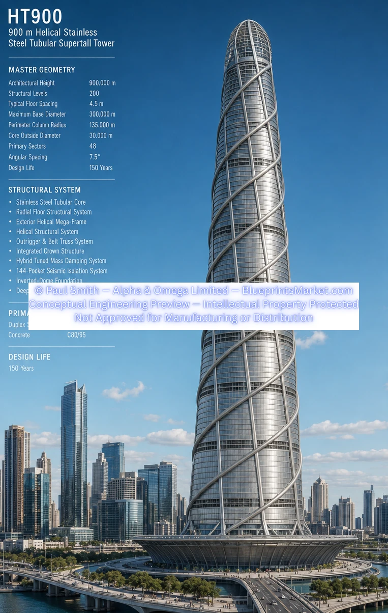
Official Master Cover Renders
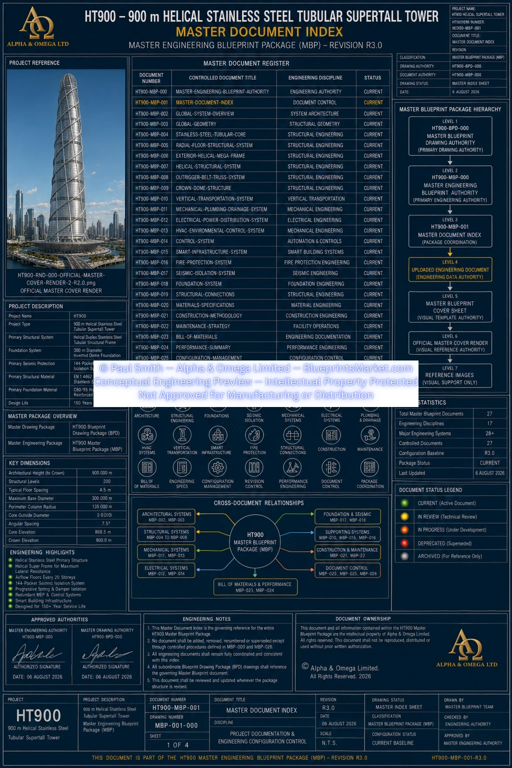
HT900-MBP-000 — Master Engineering Blueprint
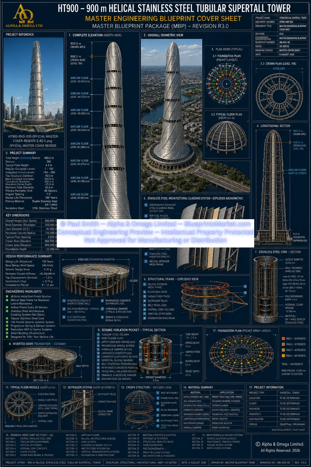
HT900-MBP-001 — Master Document Index
HT900-MBP-002 — Global System Overview
HT900-MBP-003 — Global Geometry
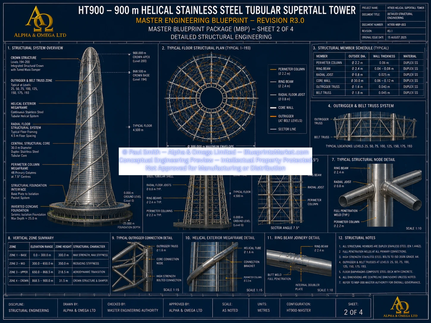
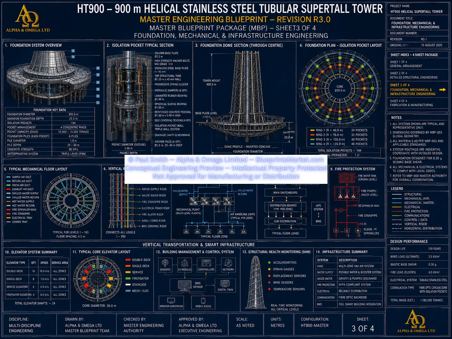
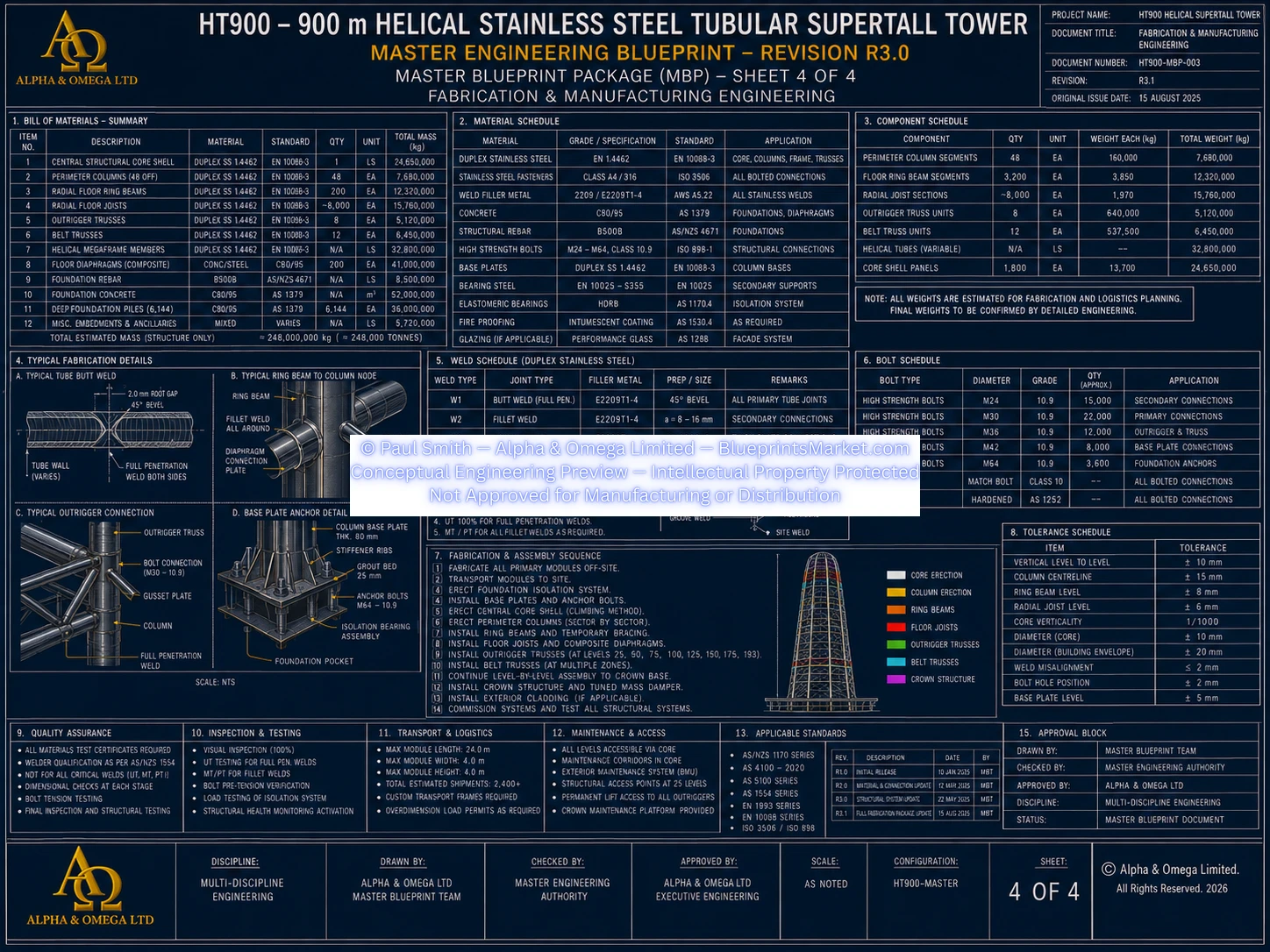
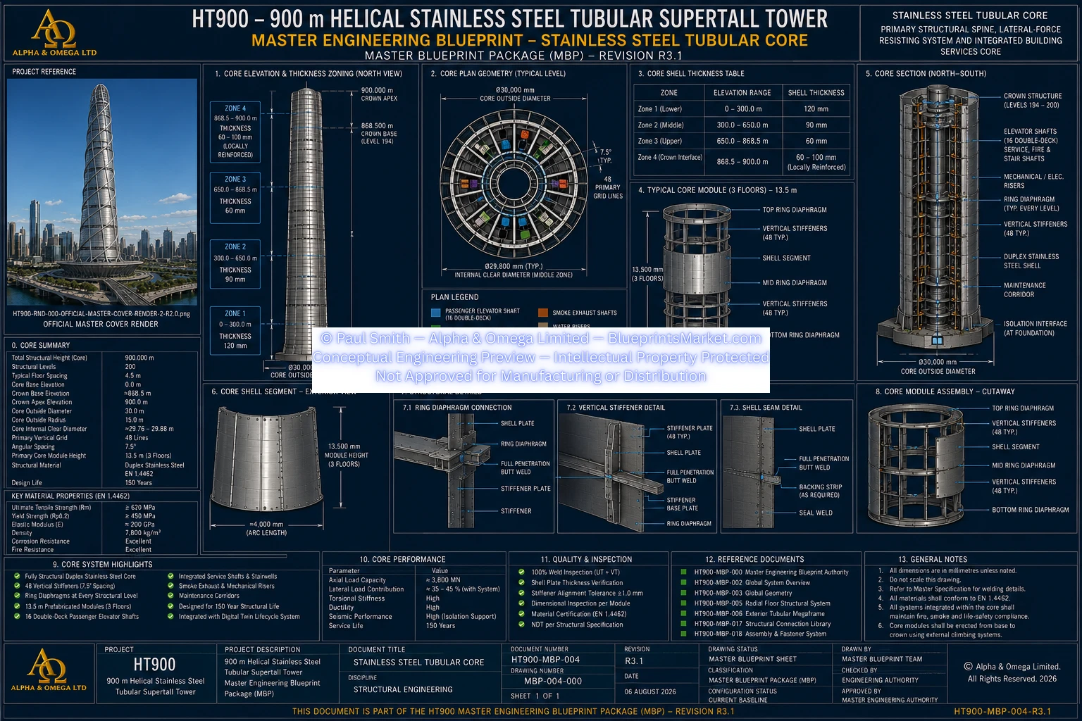
HT900-MBP-004 — Stainless Steel Tubular Core
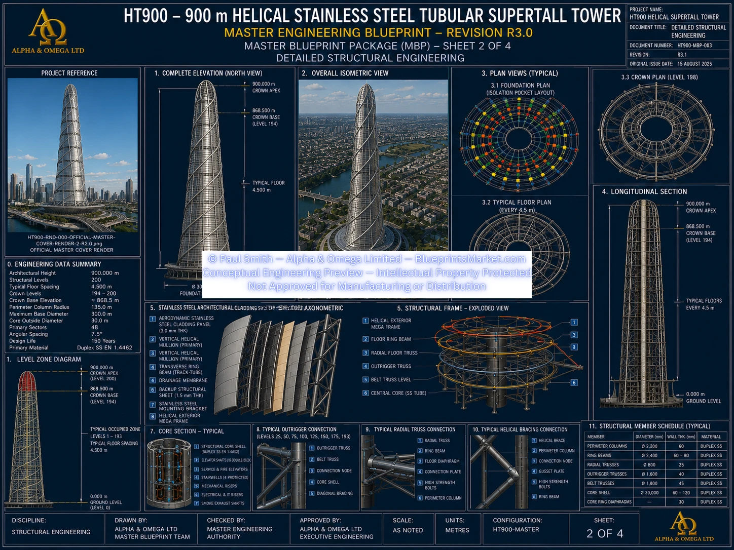
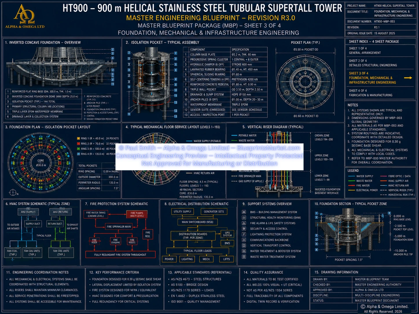
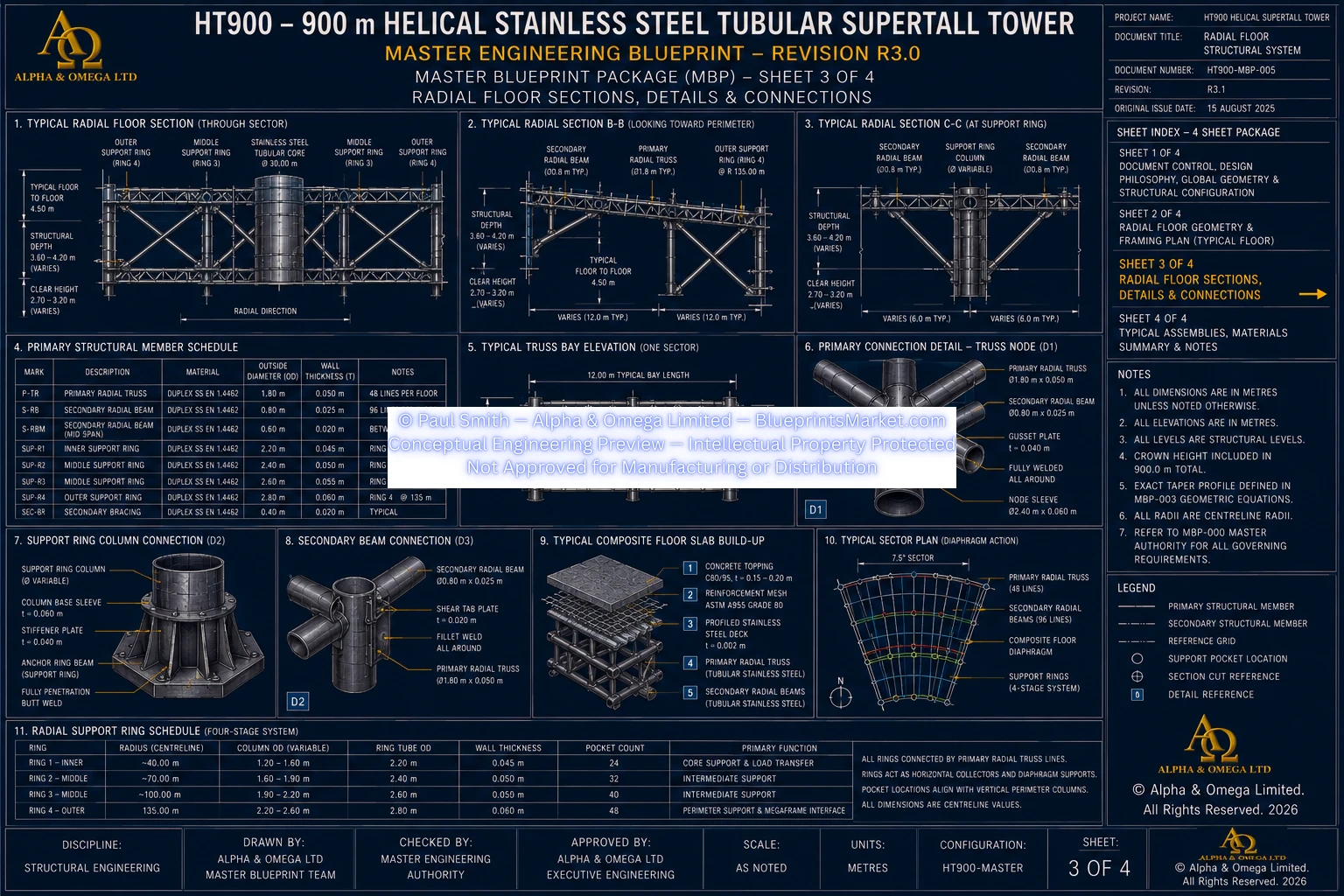
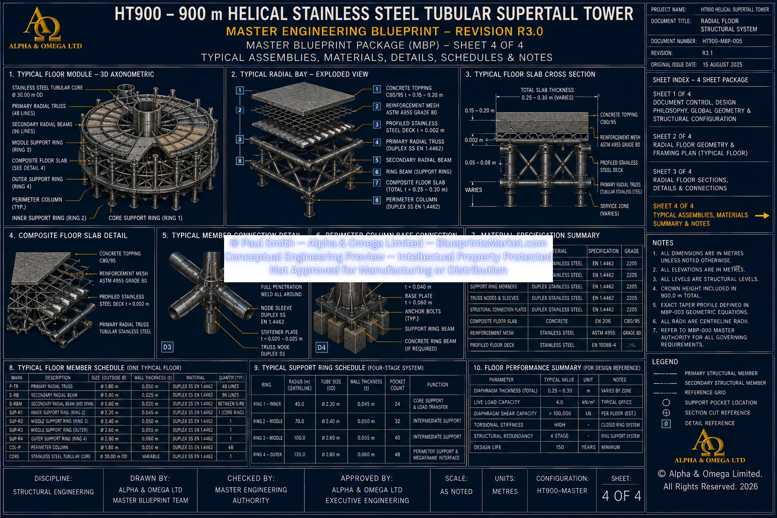
HT900-MBP-005 — Radial Floor Structural System
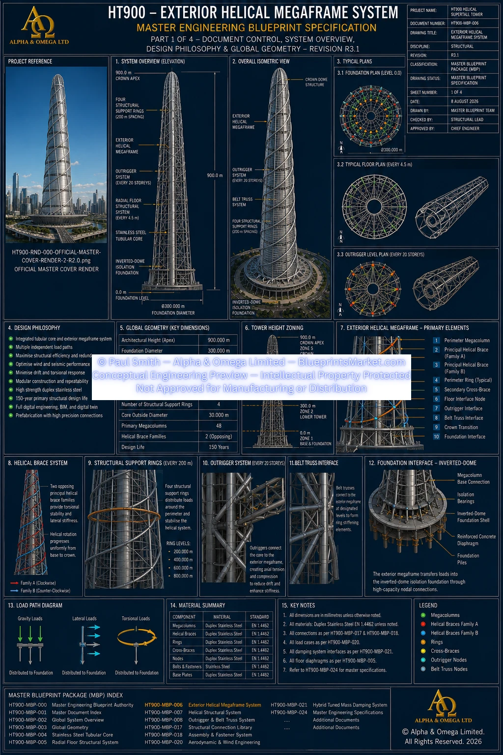
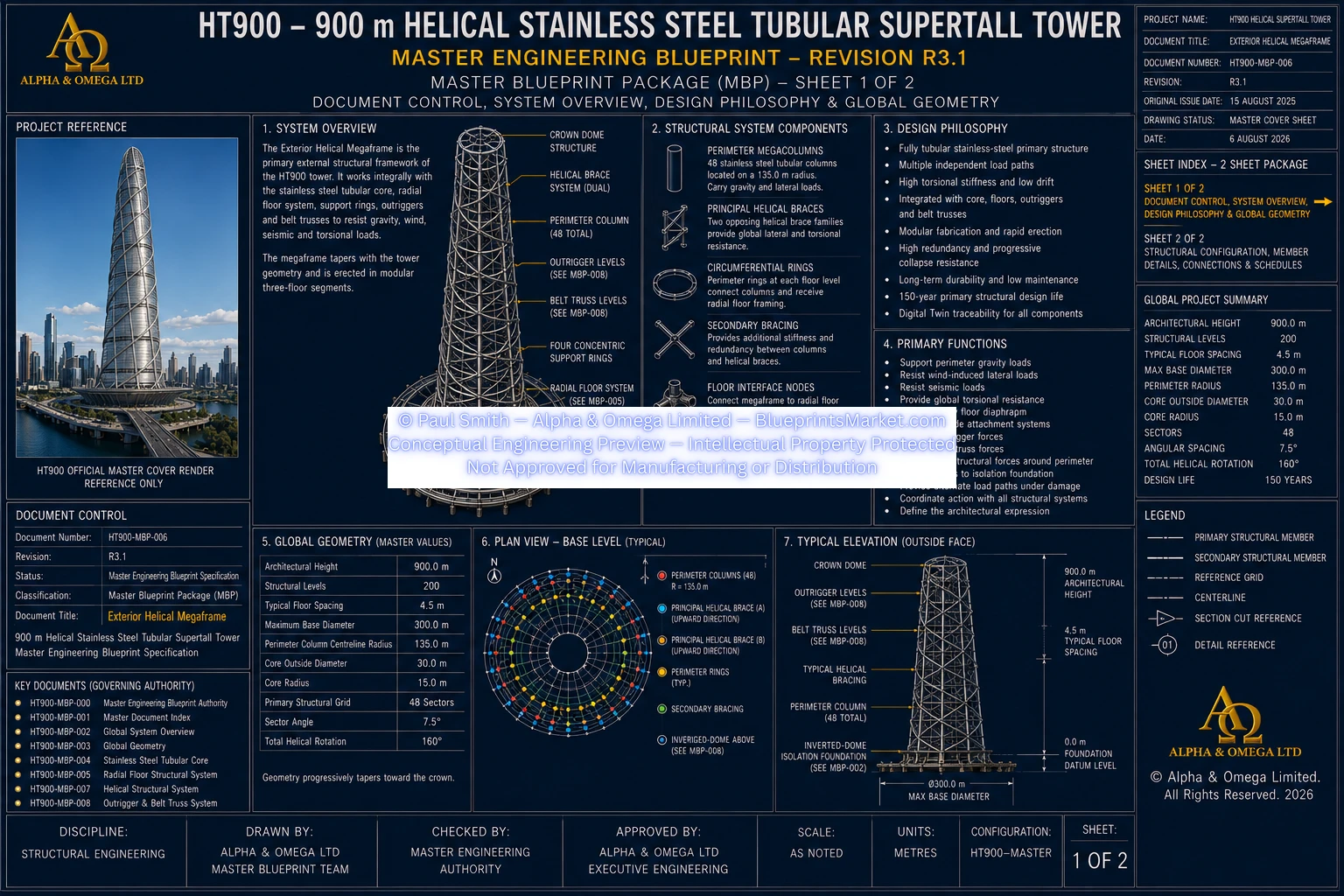
HT900-MBP-006 — Exterior Helical Mega Frame
HT900-MBP-007 — Helical Structural System
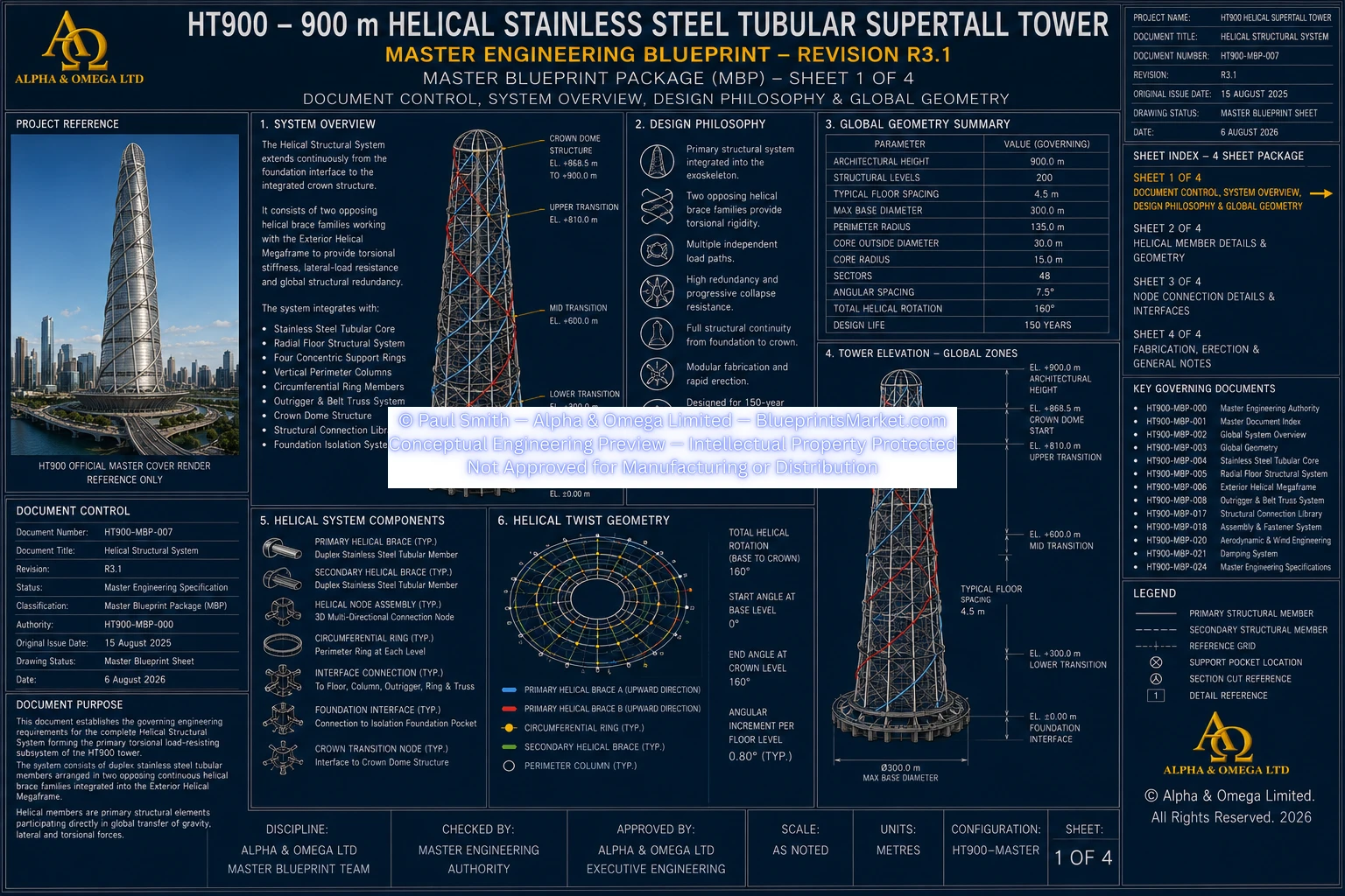
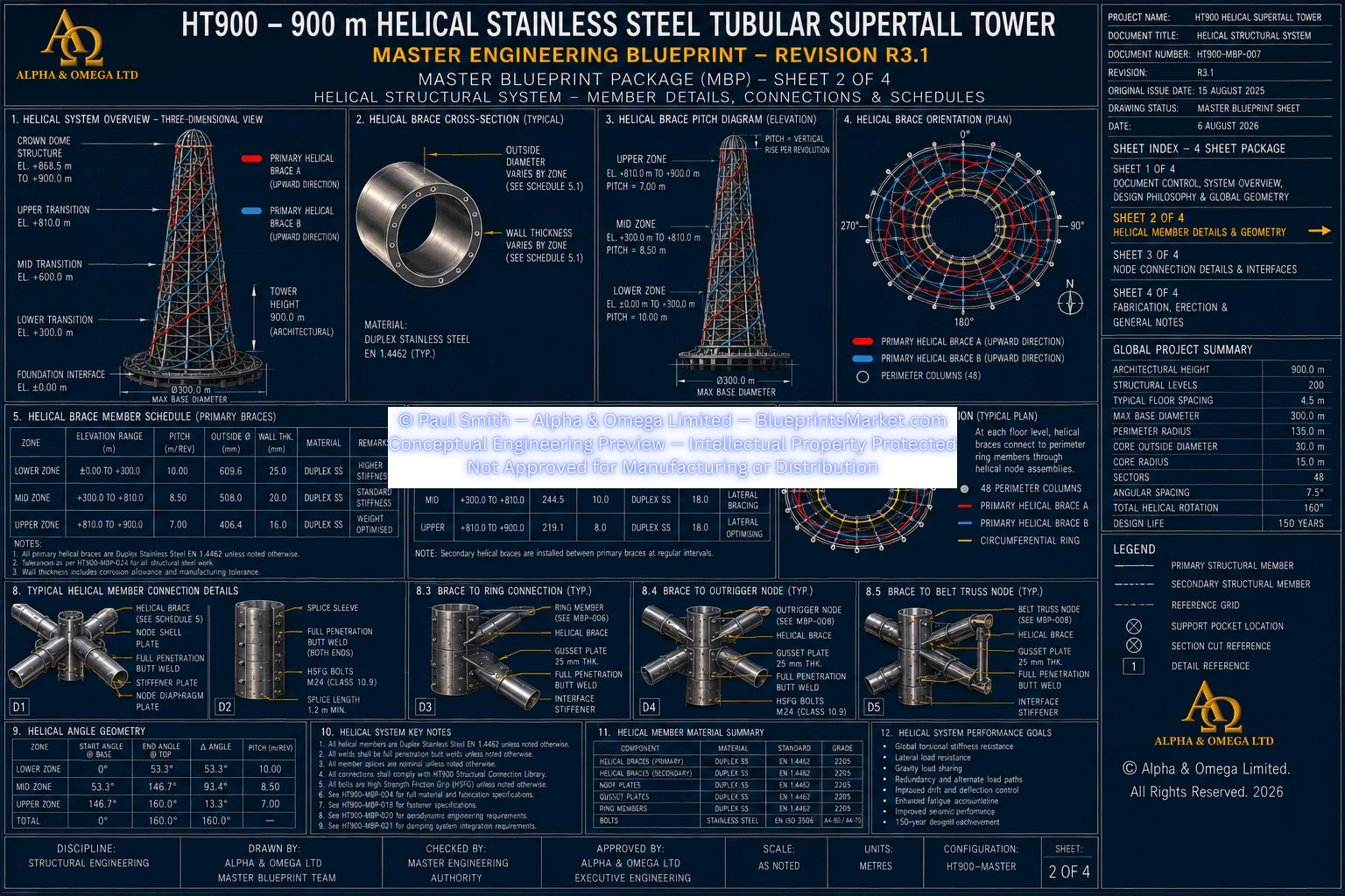
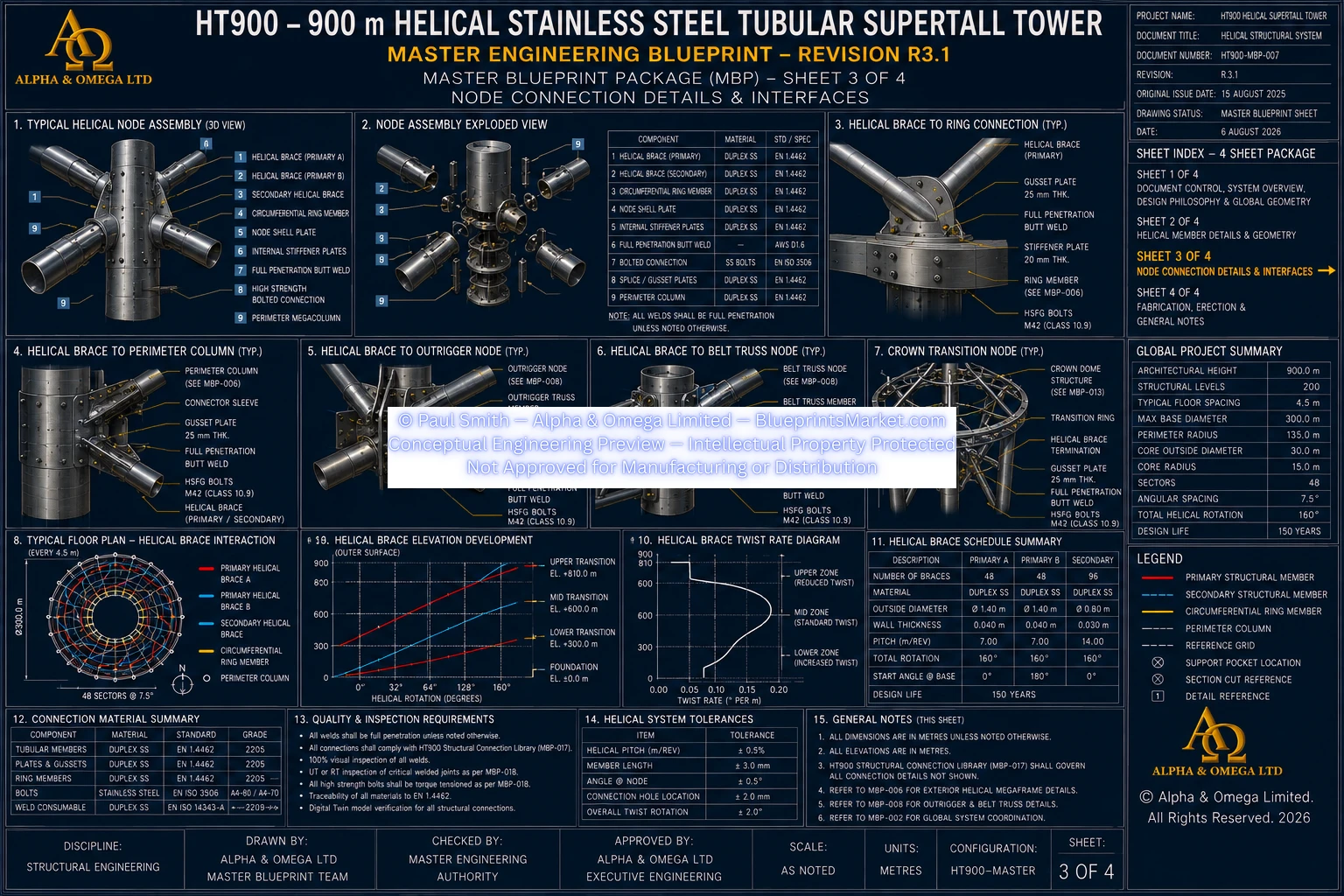
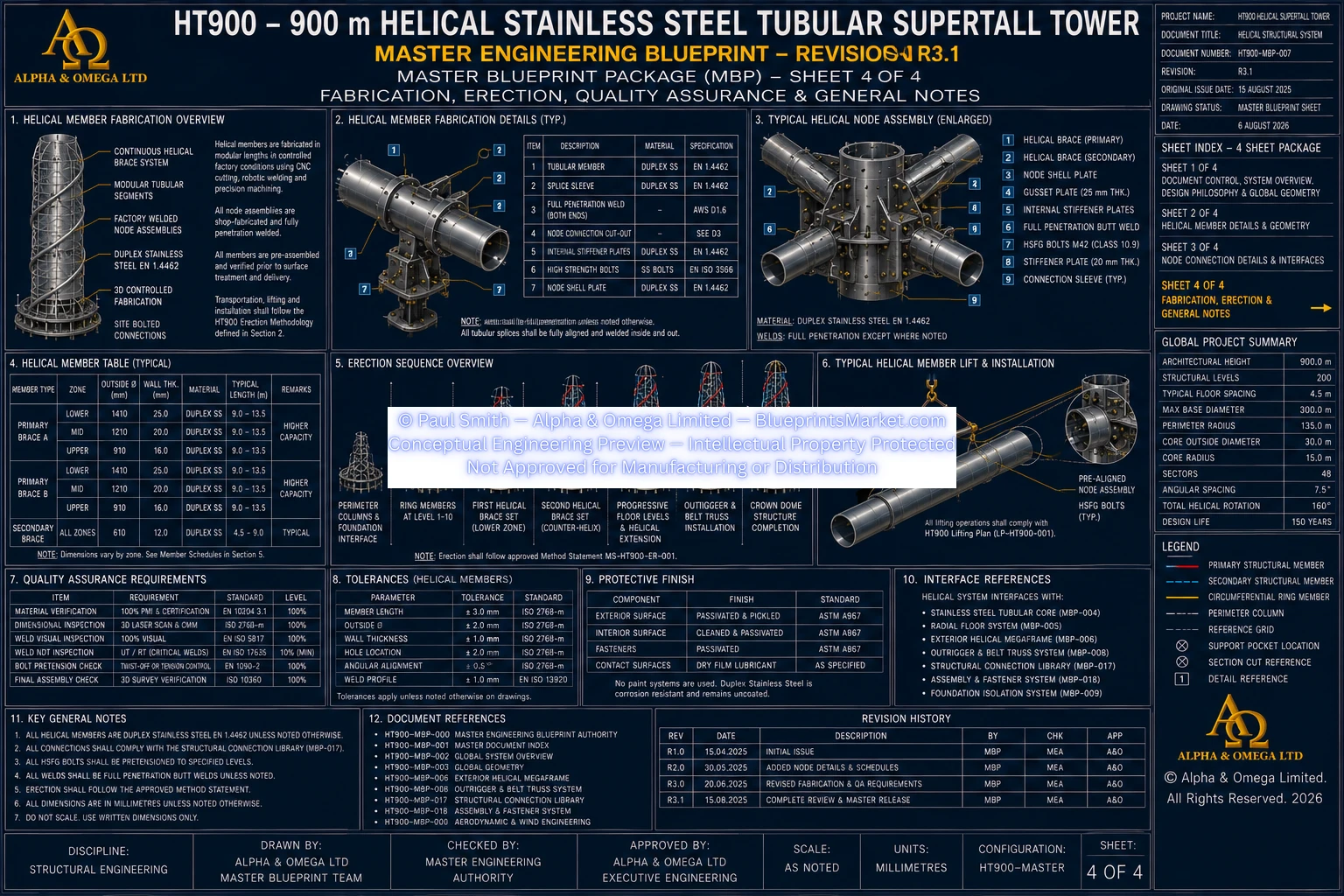
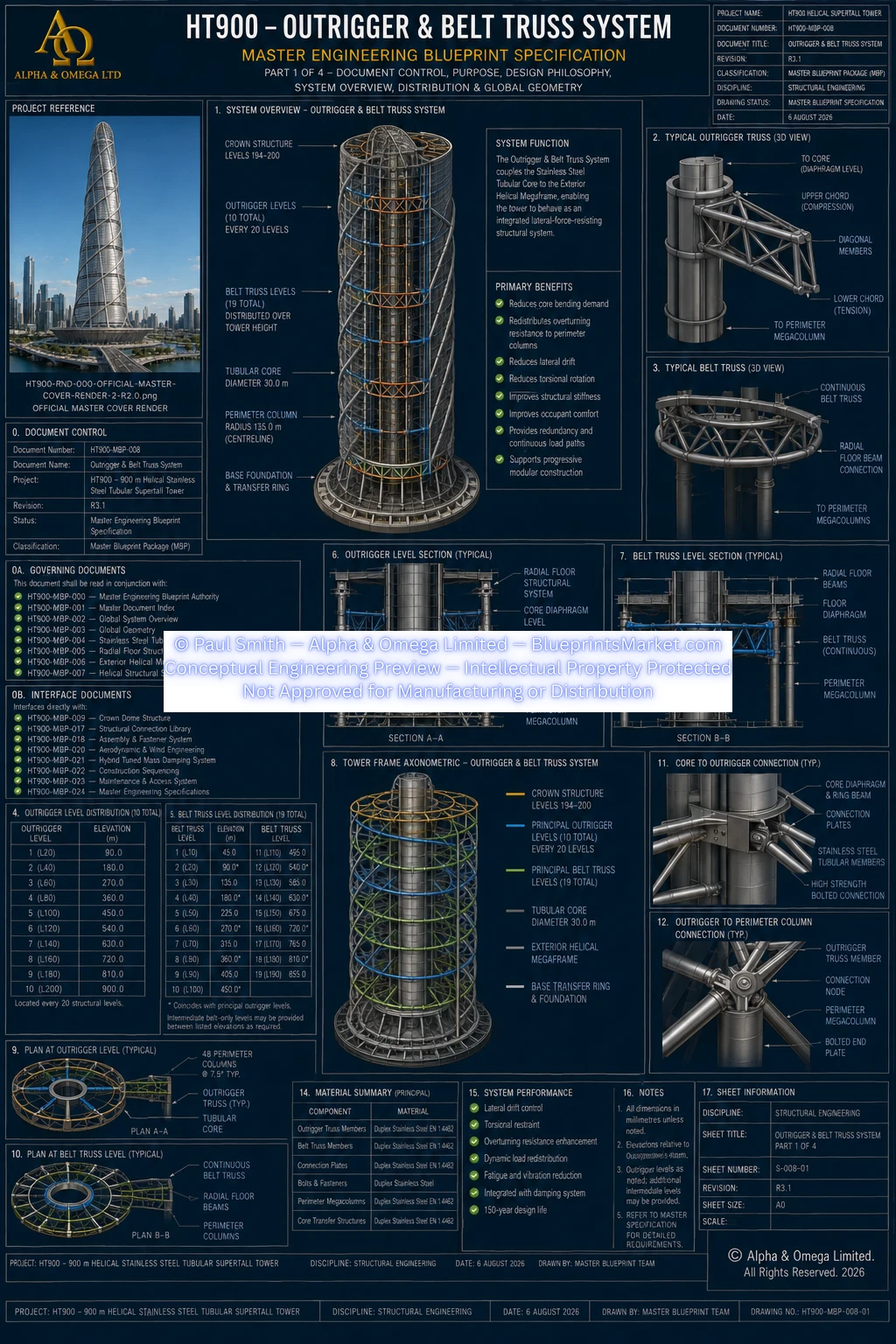
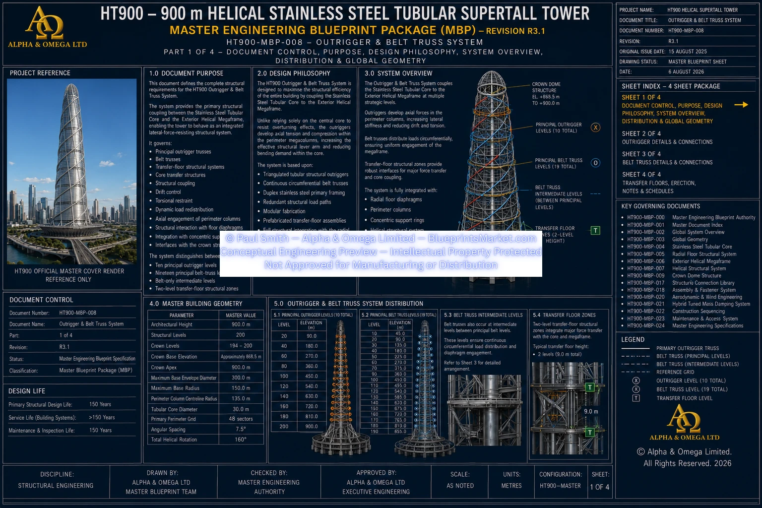
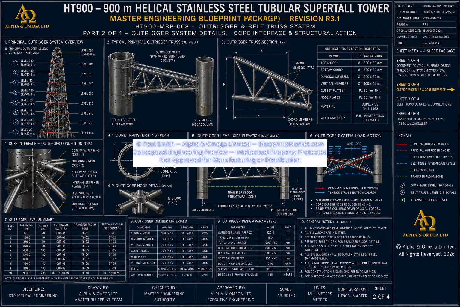
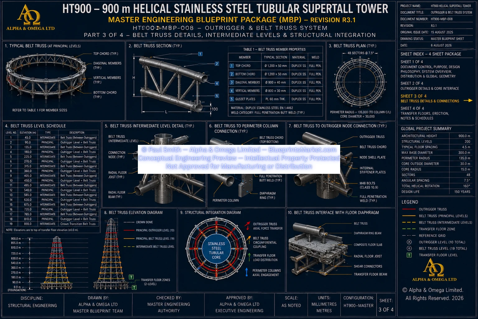
HT900-MBP-008 — Outrigger & Belt Truss System
HT900-MBP-009 — Crown Dome Structure
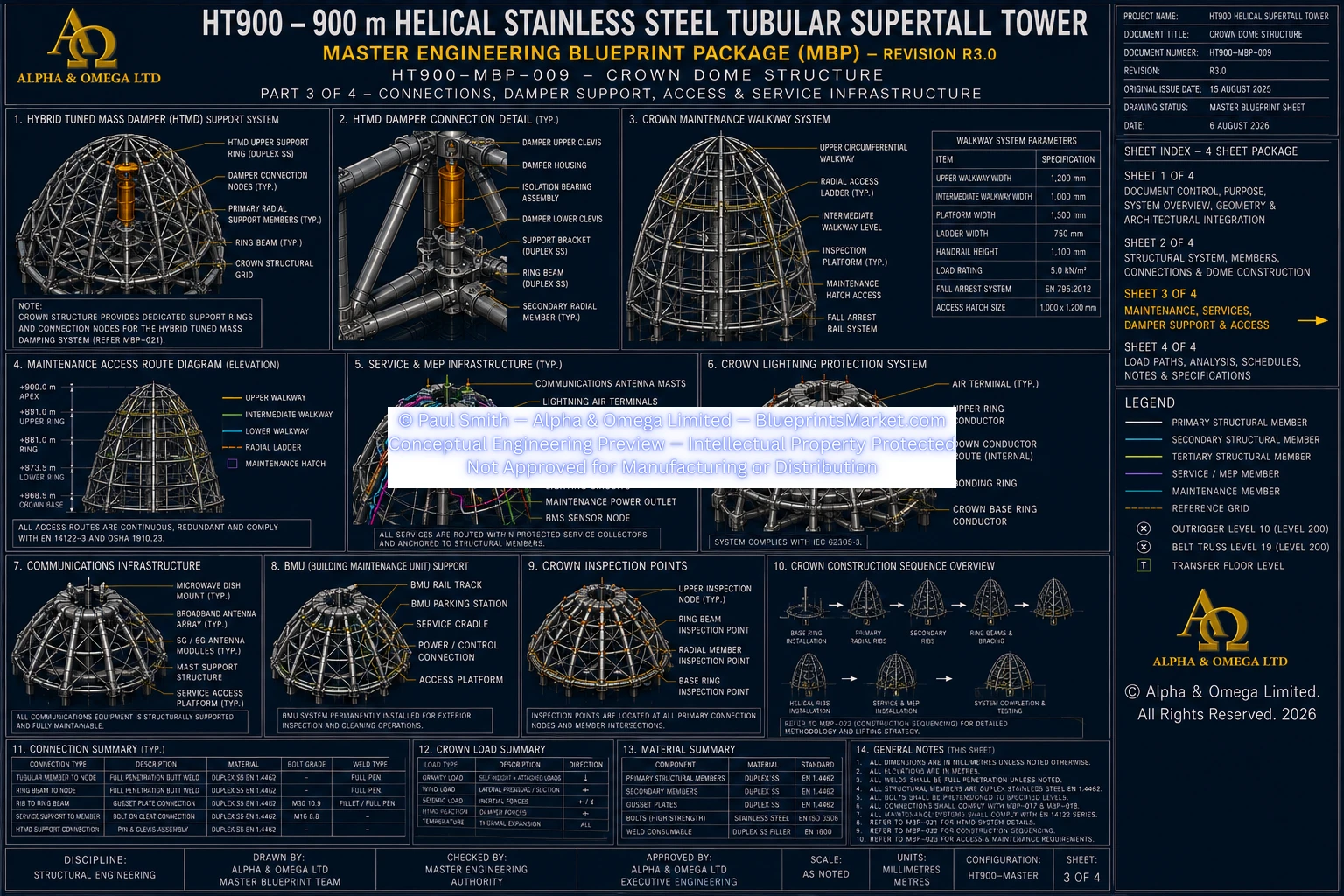
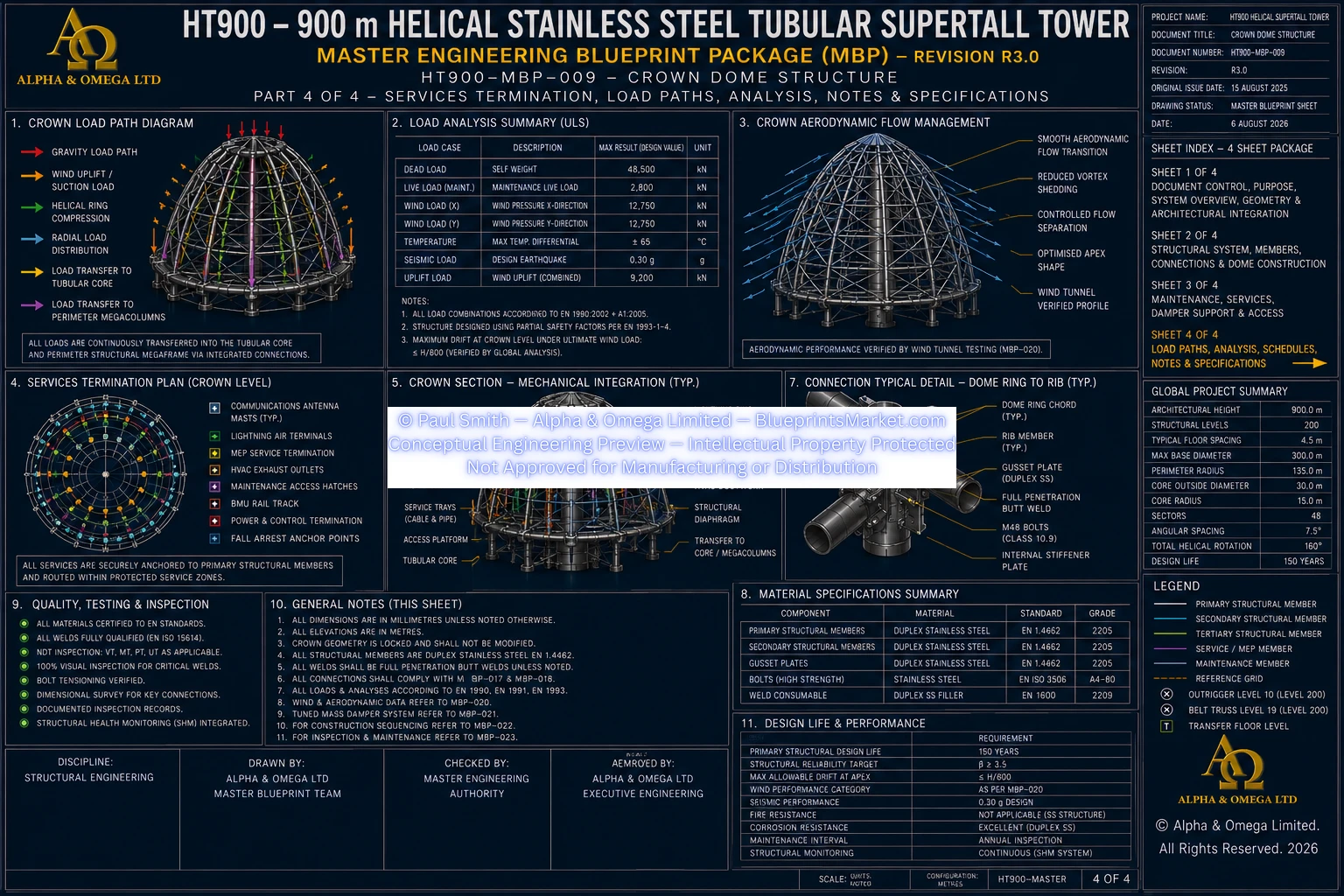
HT900-MBP-010 — Vertical Transportation System
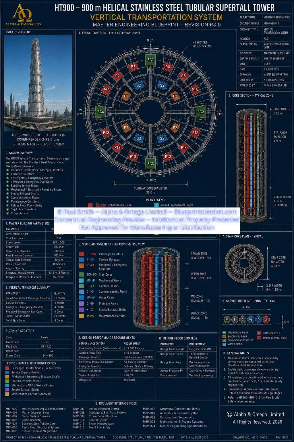
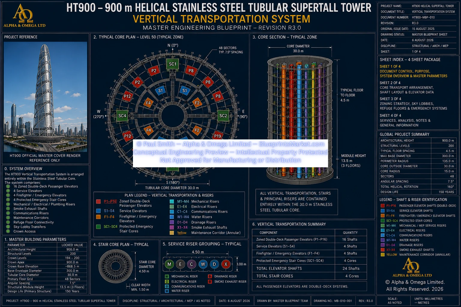
HT900-MBP-011 — Mechanical, Plumbing & Drainage System
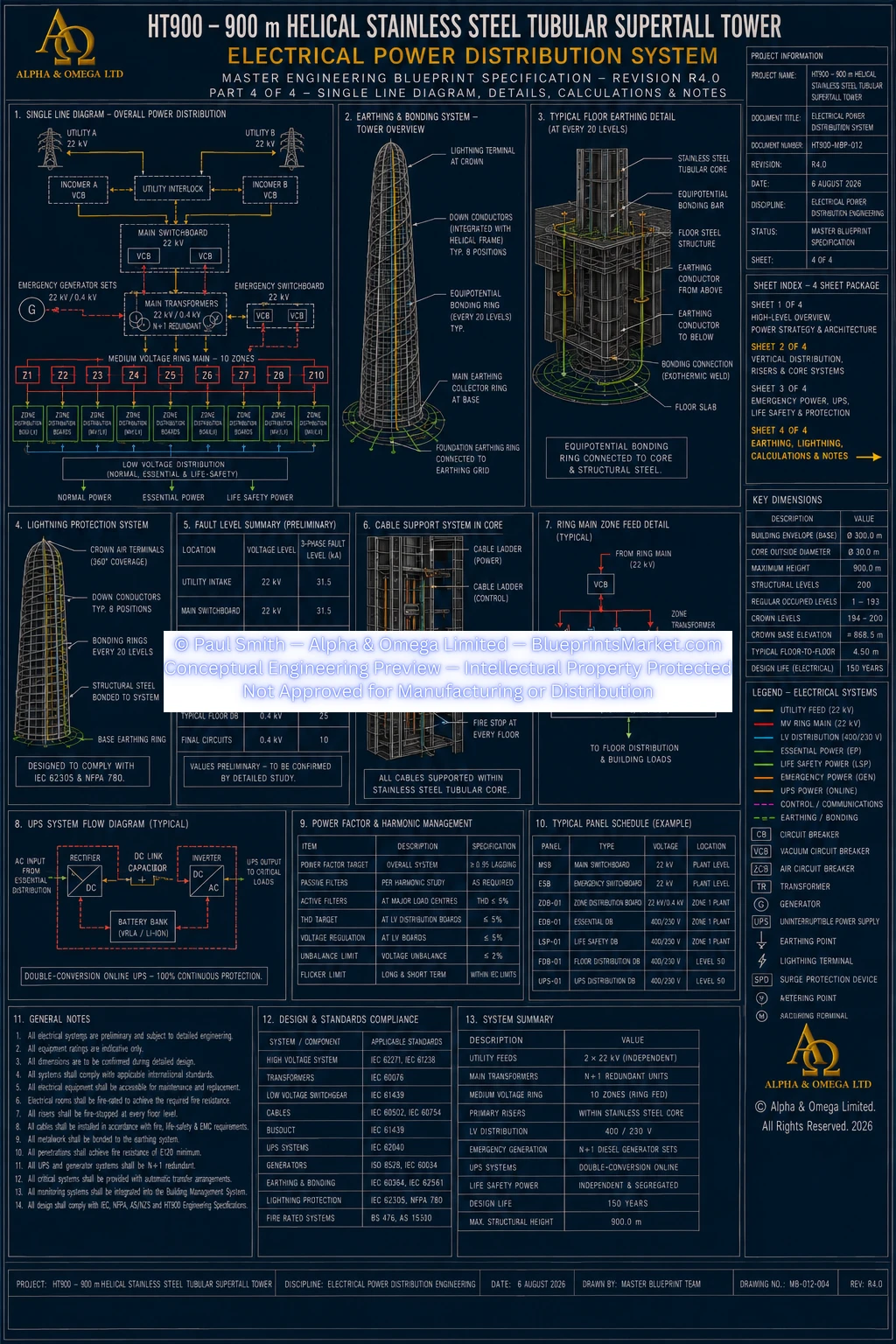
HT900-MBP-012 — Electrical Power Distribution System
HT900-MBP-013 — HVAC Environmental Control System
HT900-MBP-014 — Control System
HT900-MBP-015 — Smart Infrastructure System
HT900-MBP-016 — Fire & Life Safety System
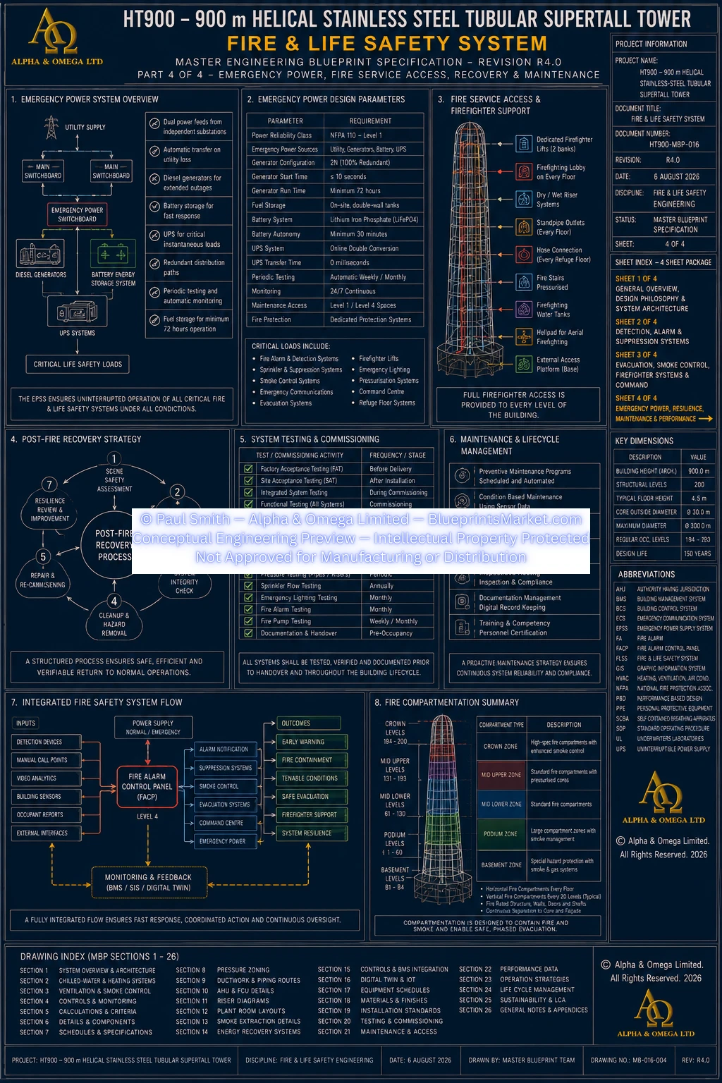
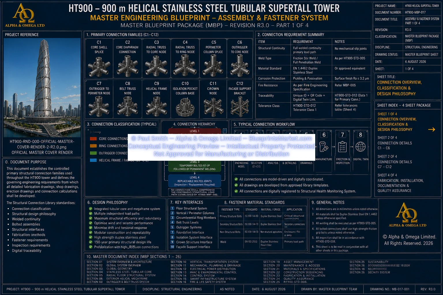
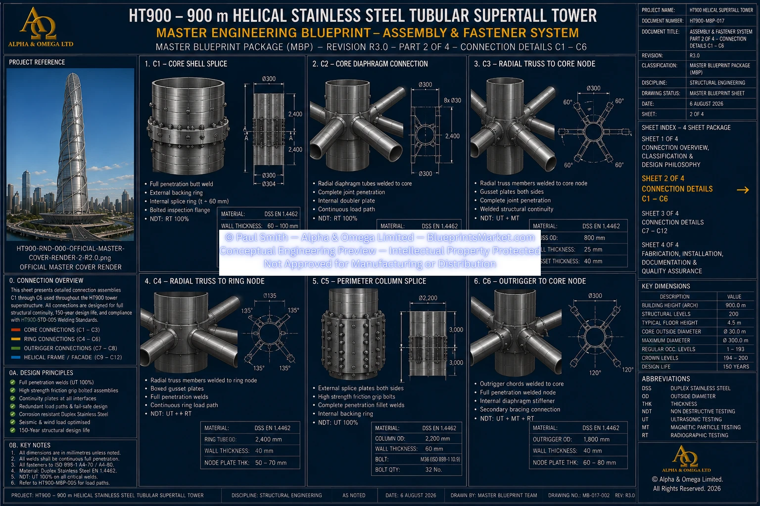
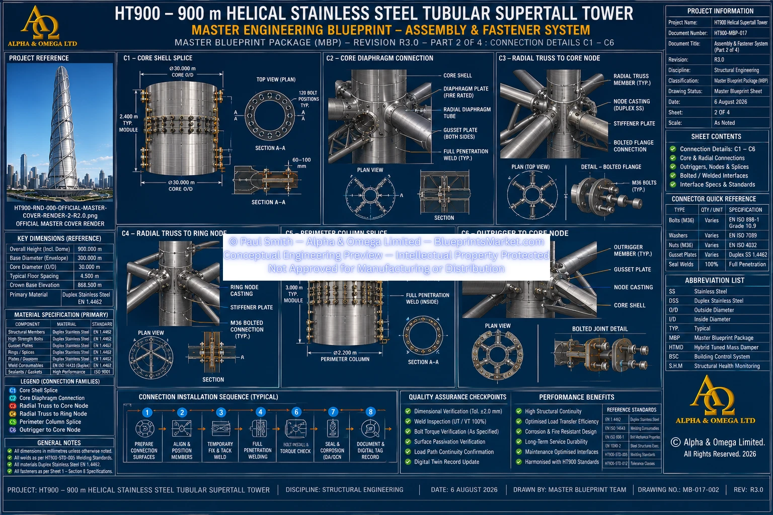
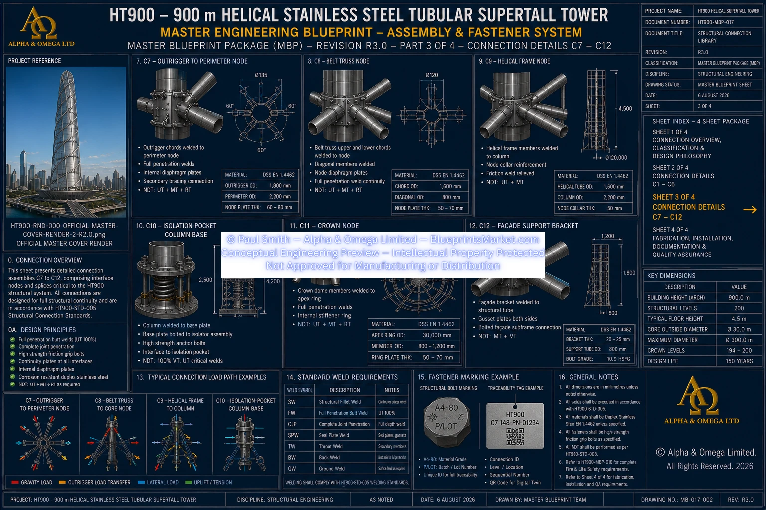
HT900-MBP-017 — Structural Connection Library
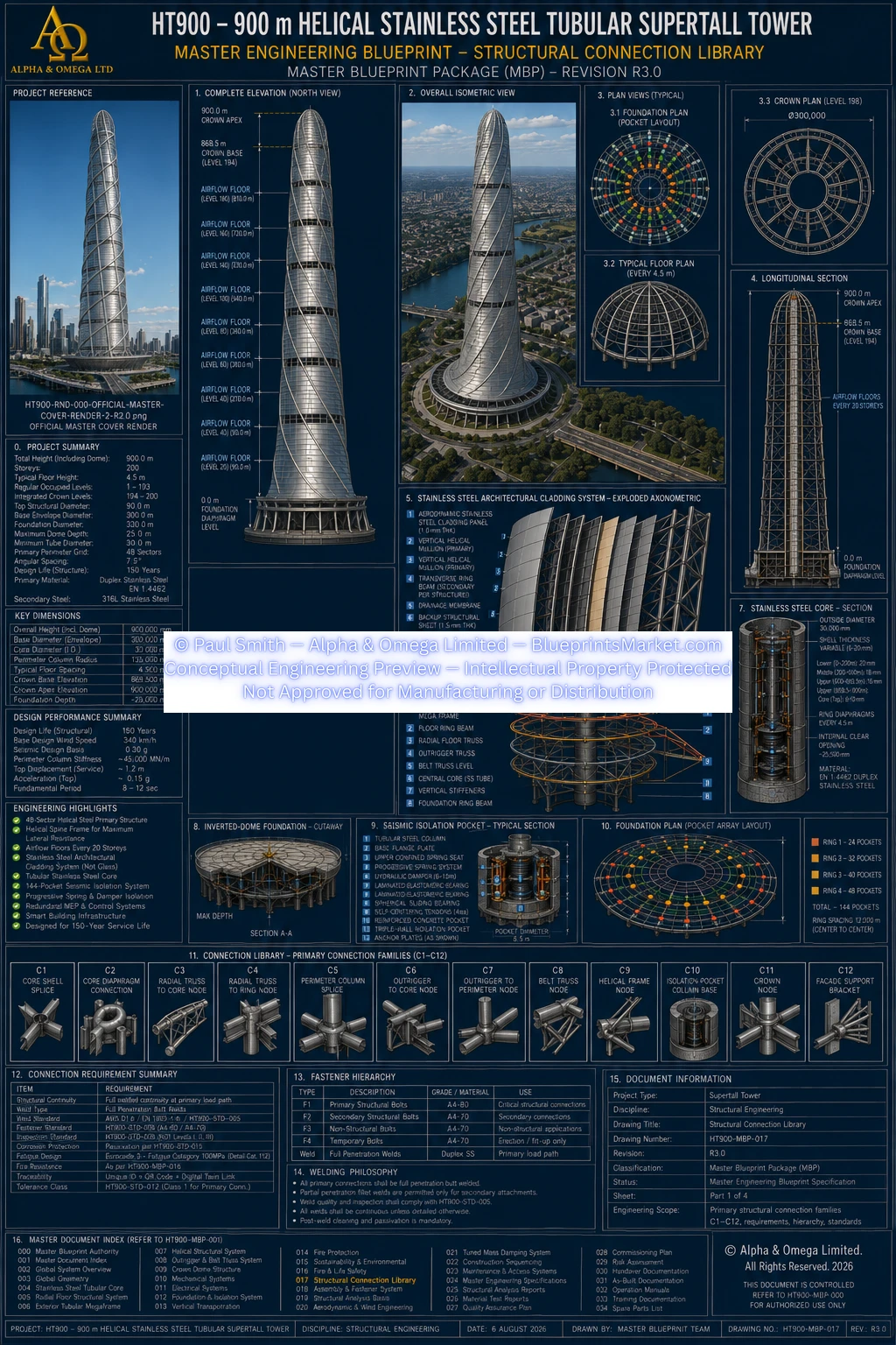
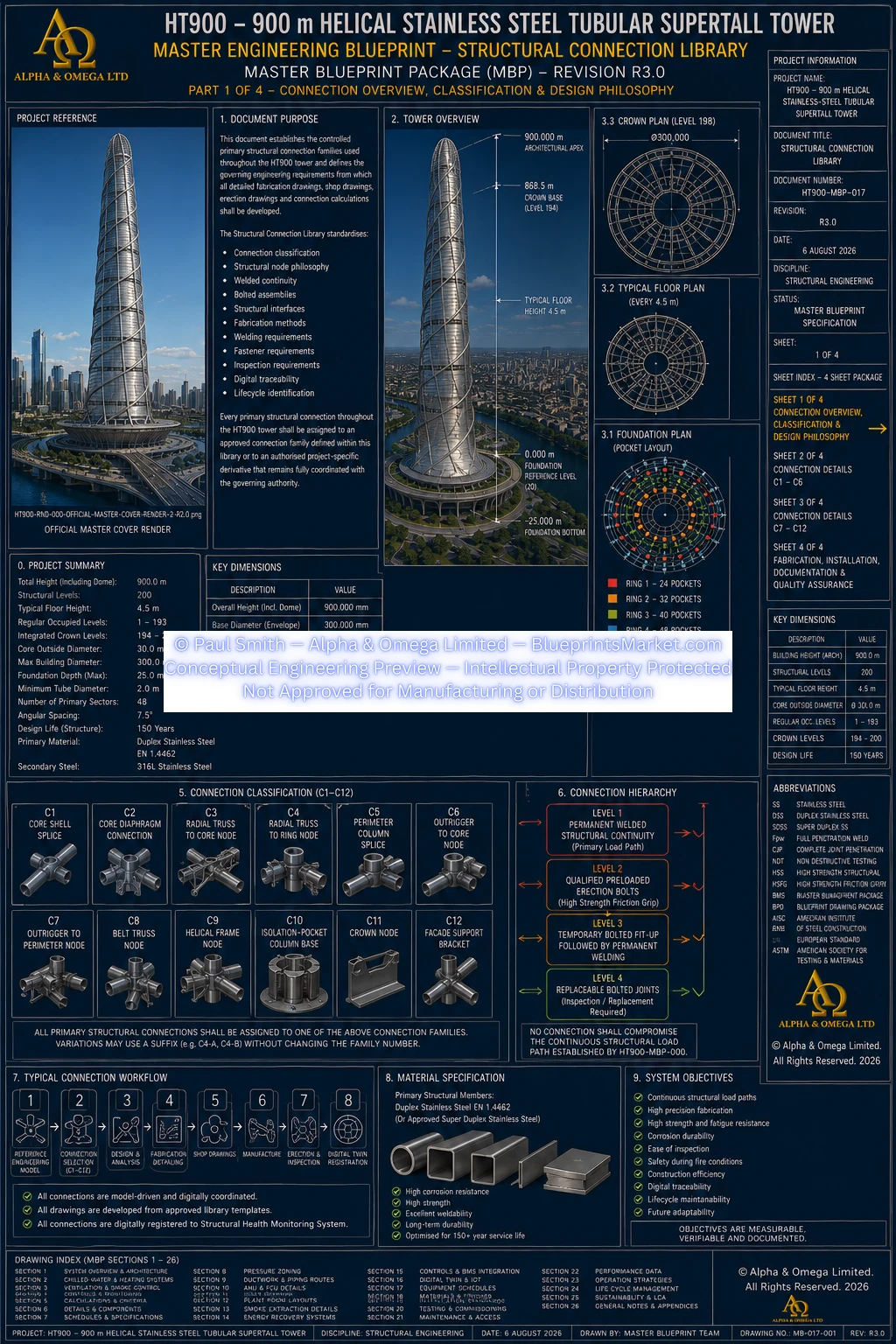
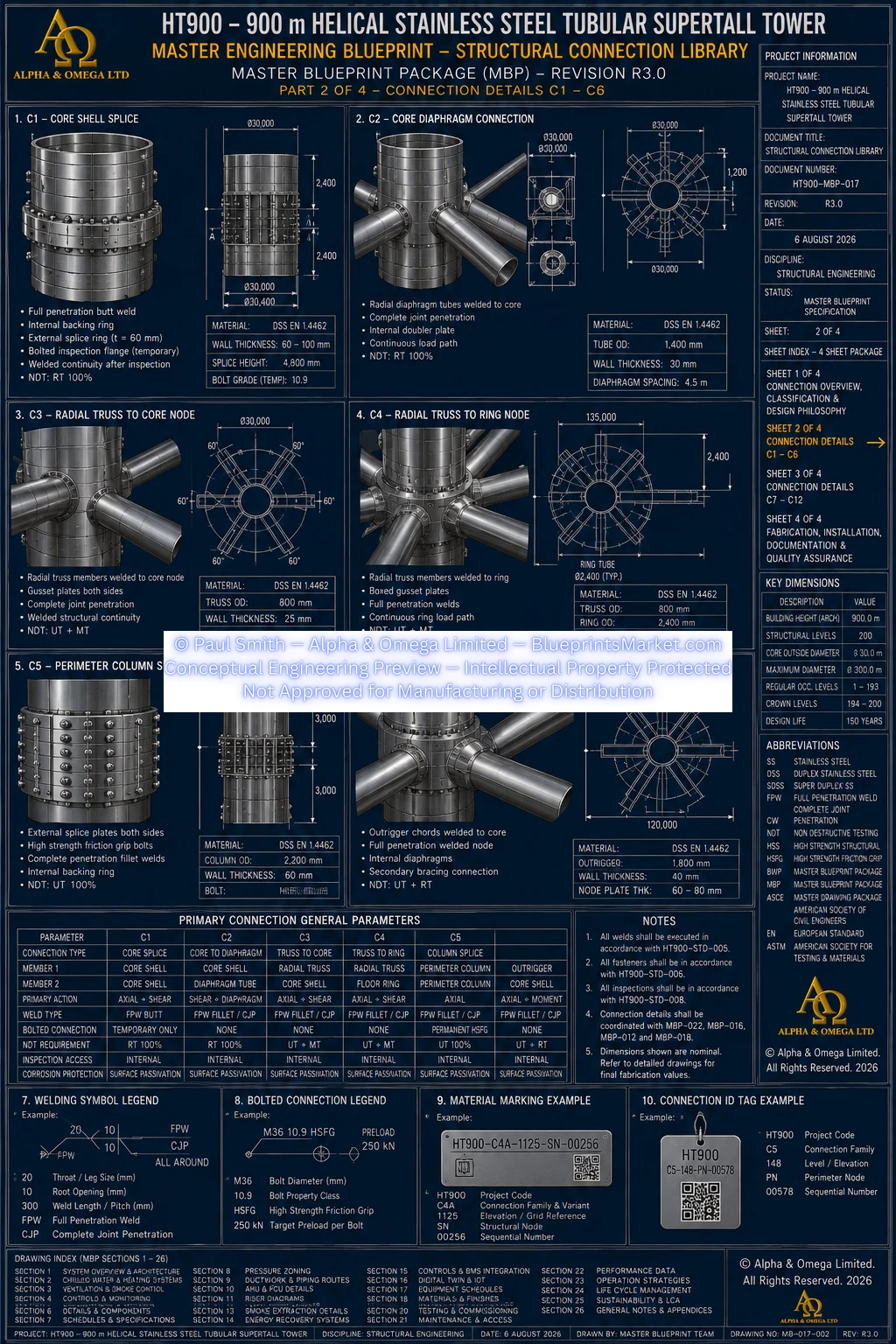
HT900-MBP-018 — Assembly & Fastener System
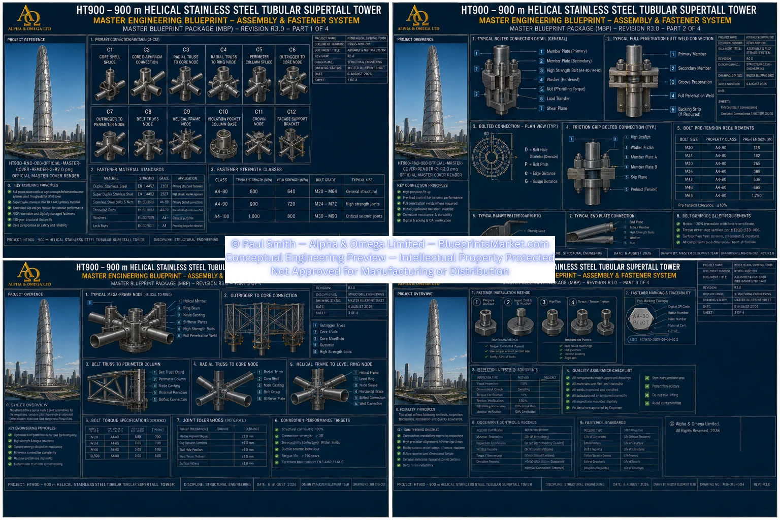
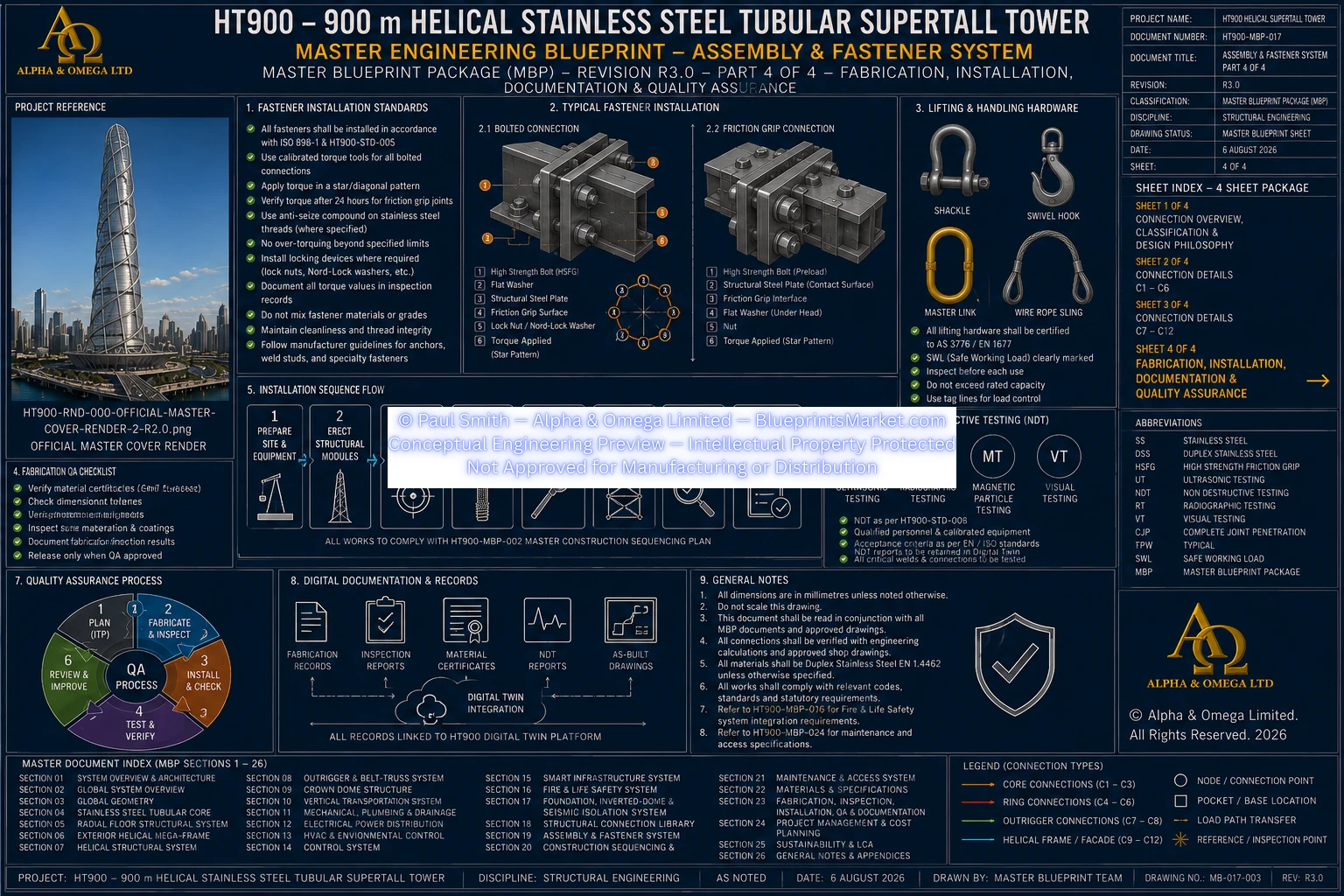
HT900-MBP-019 — Bill of Materials & Consolidated Master Parts Register
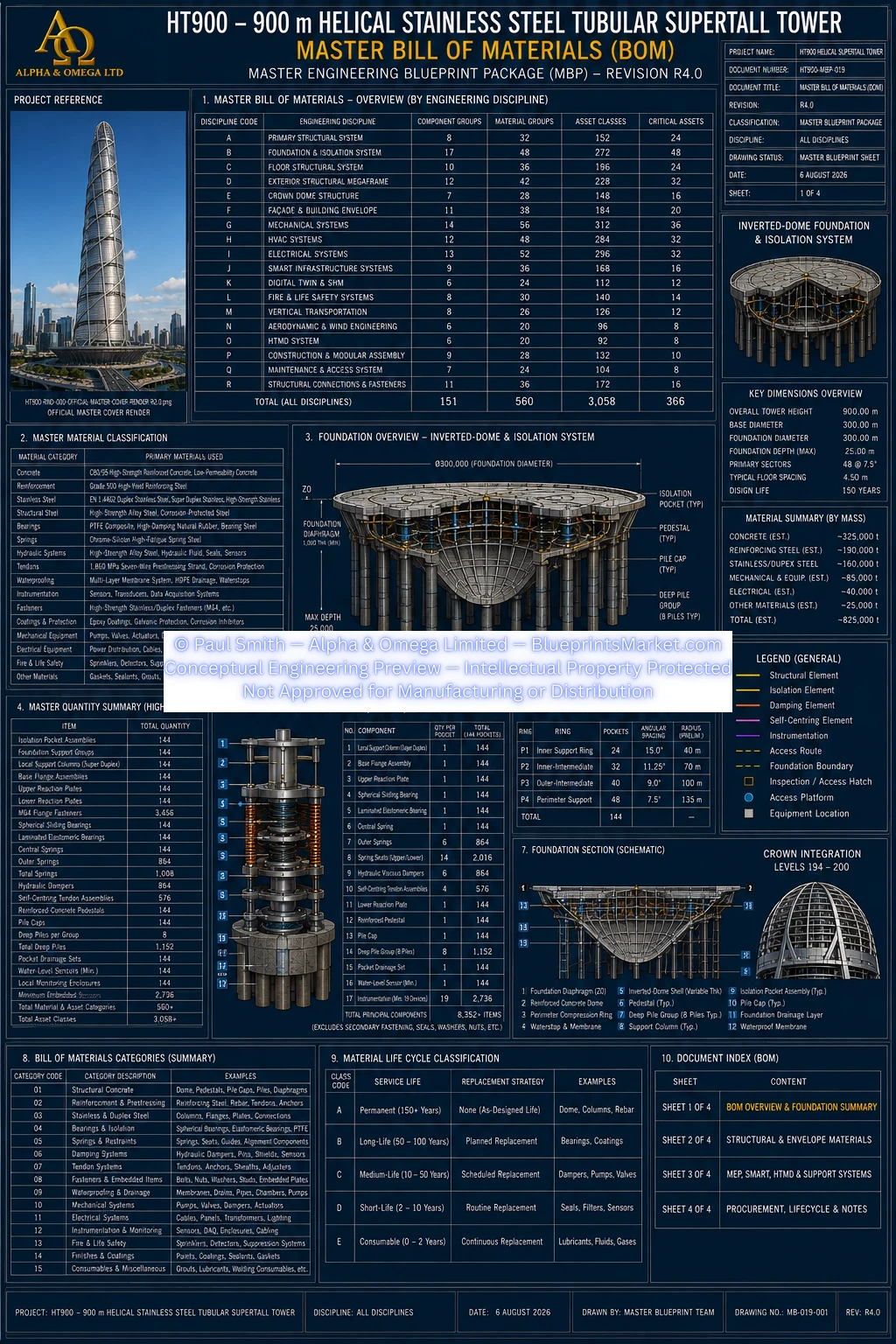
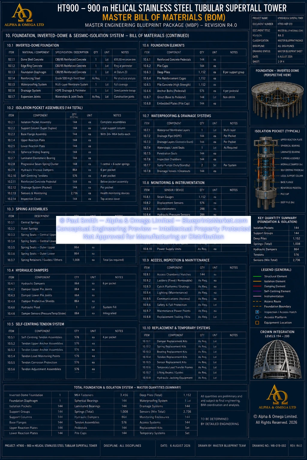
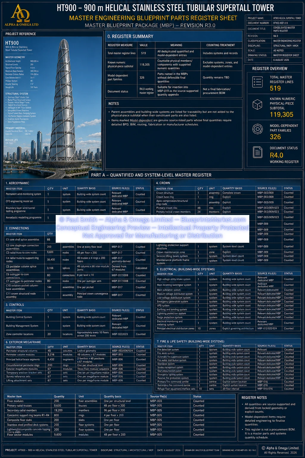
HT900-MBP-020 — Aerodynamic & Wind Engineering
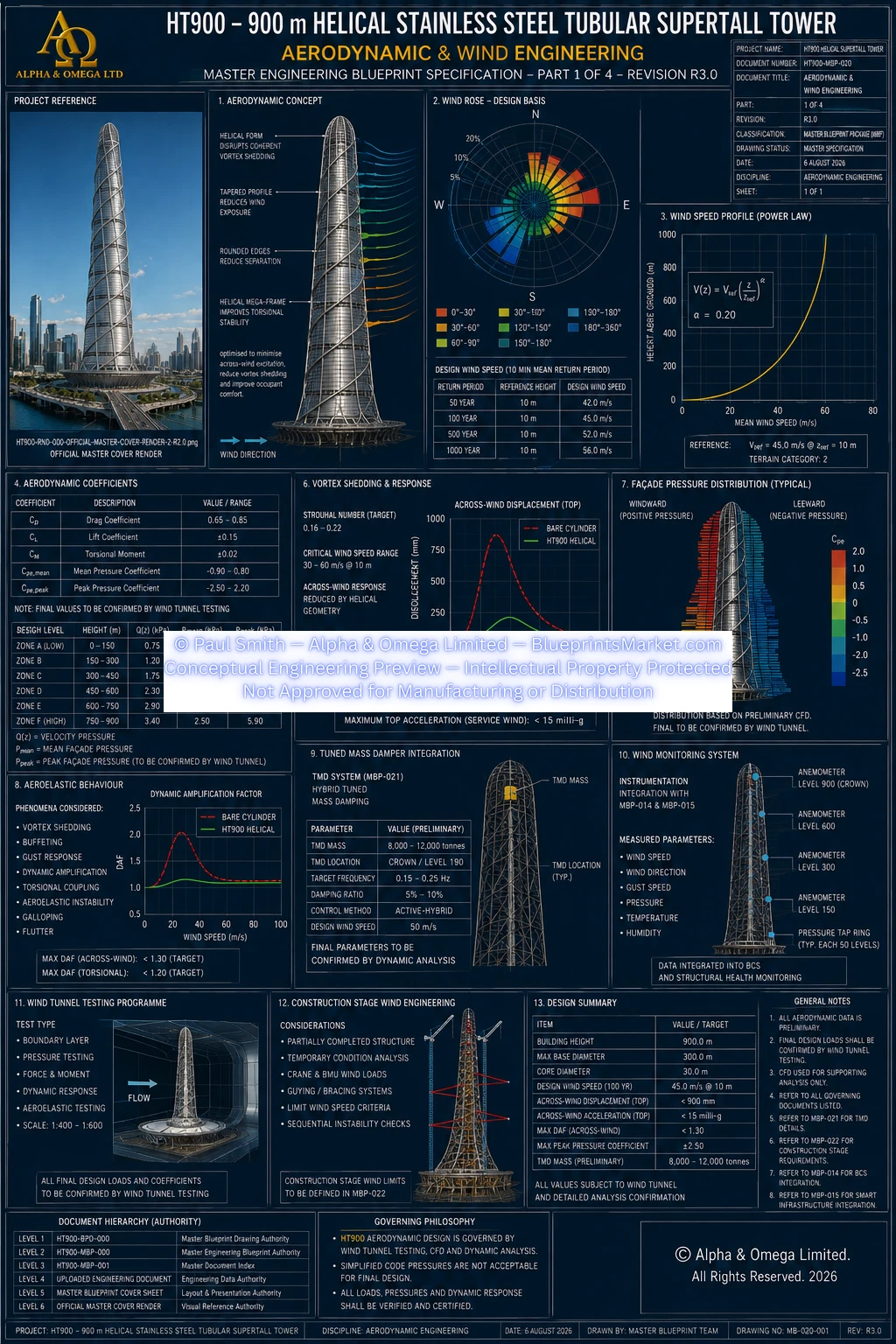
HT900-MBP-021 — Tuned Mass Damping System
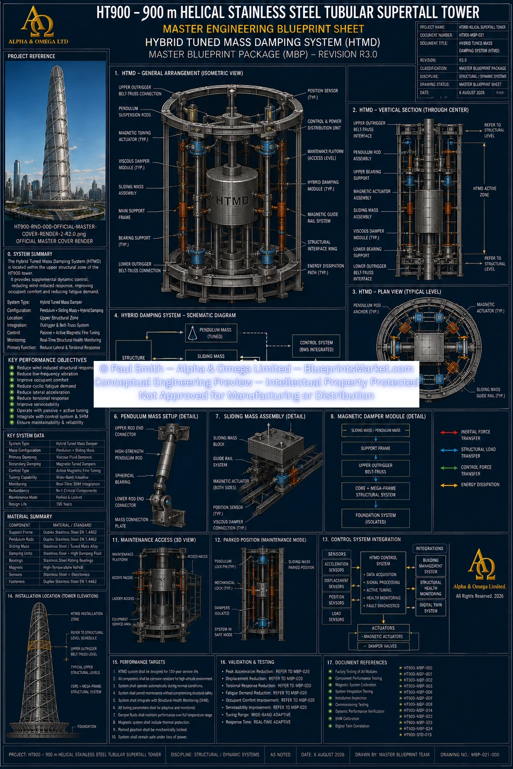
HT900-MBP-022 — Construction Sequencing
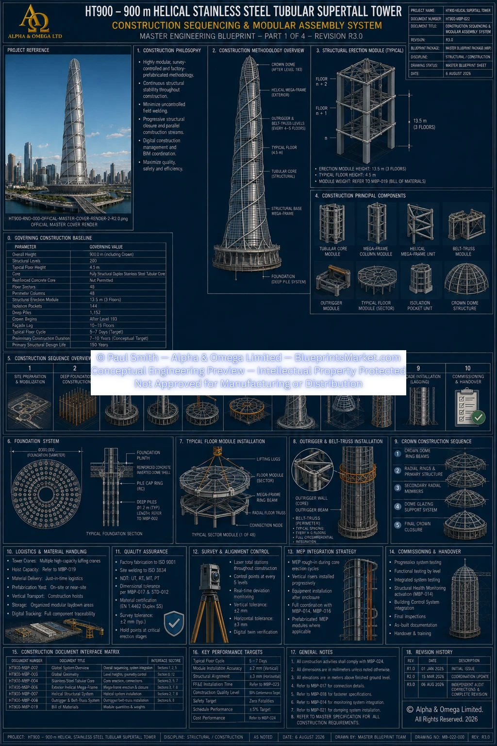
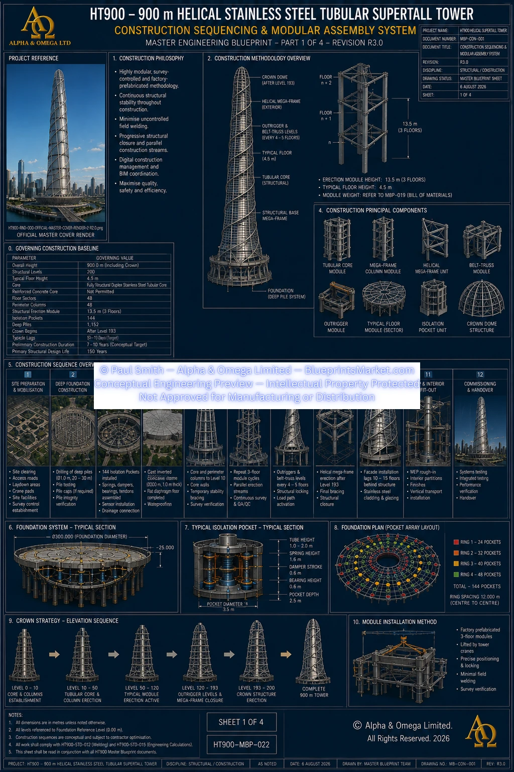
HT900-MBP-023 — Maintenance & Access System
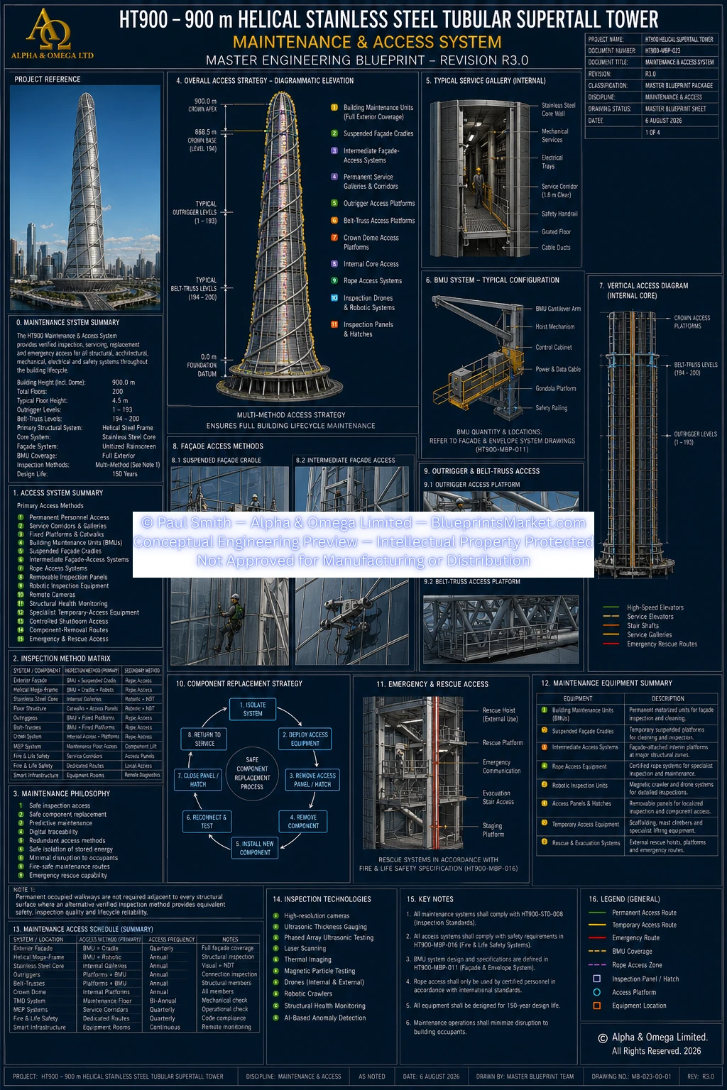
HT900-MBP-024 — Master Engineering Specifications
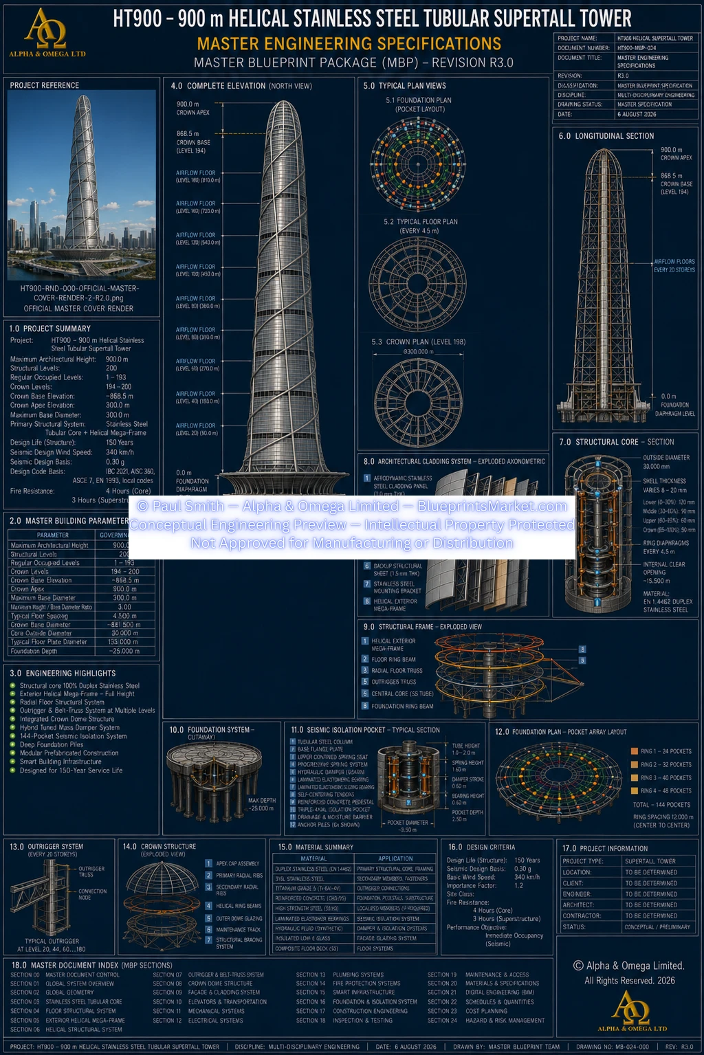
HT900-MBP-025 — Foundation, Inverted Dome & Seismic Isolation System
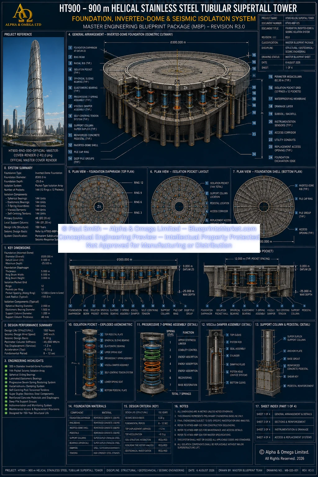
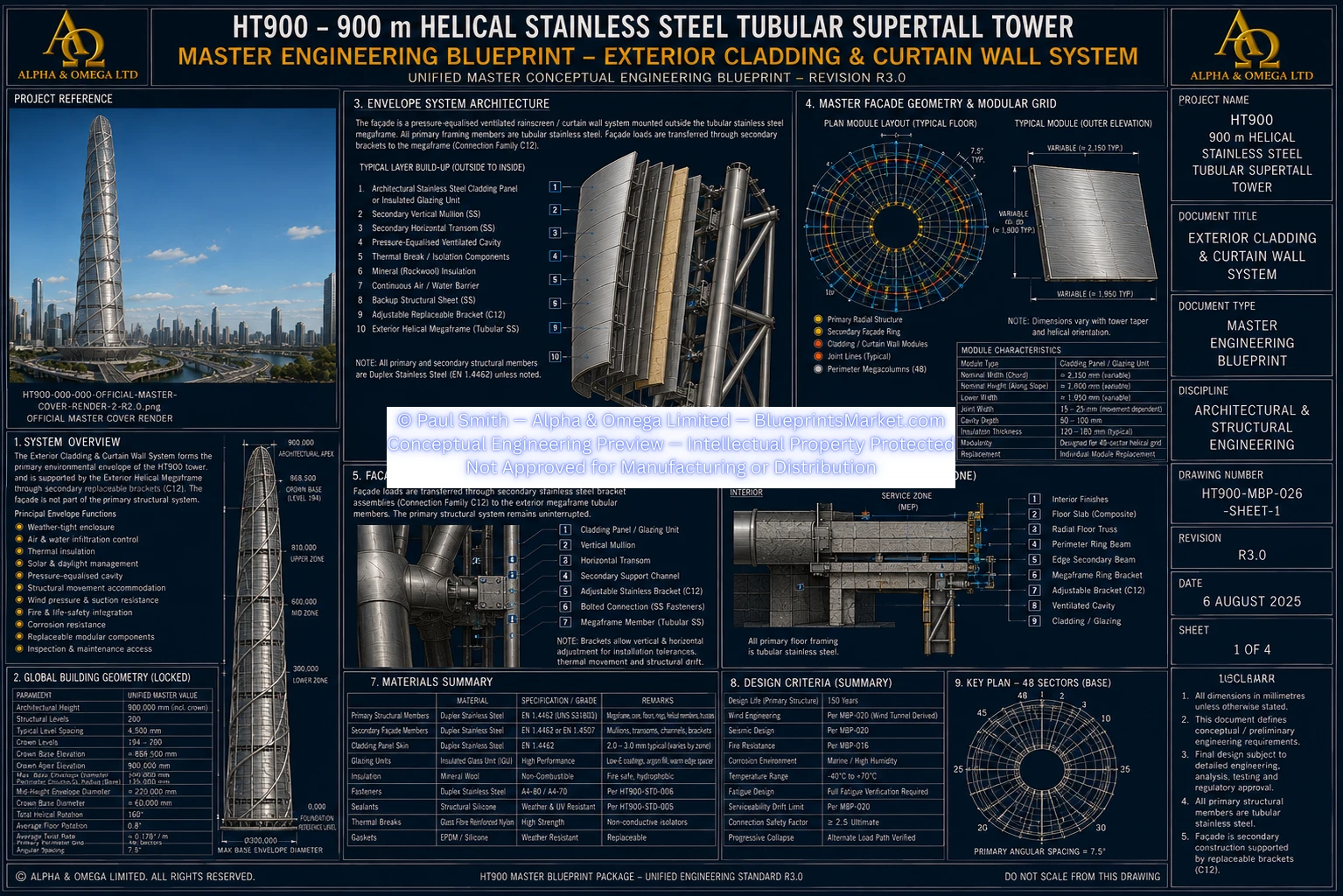
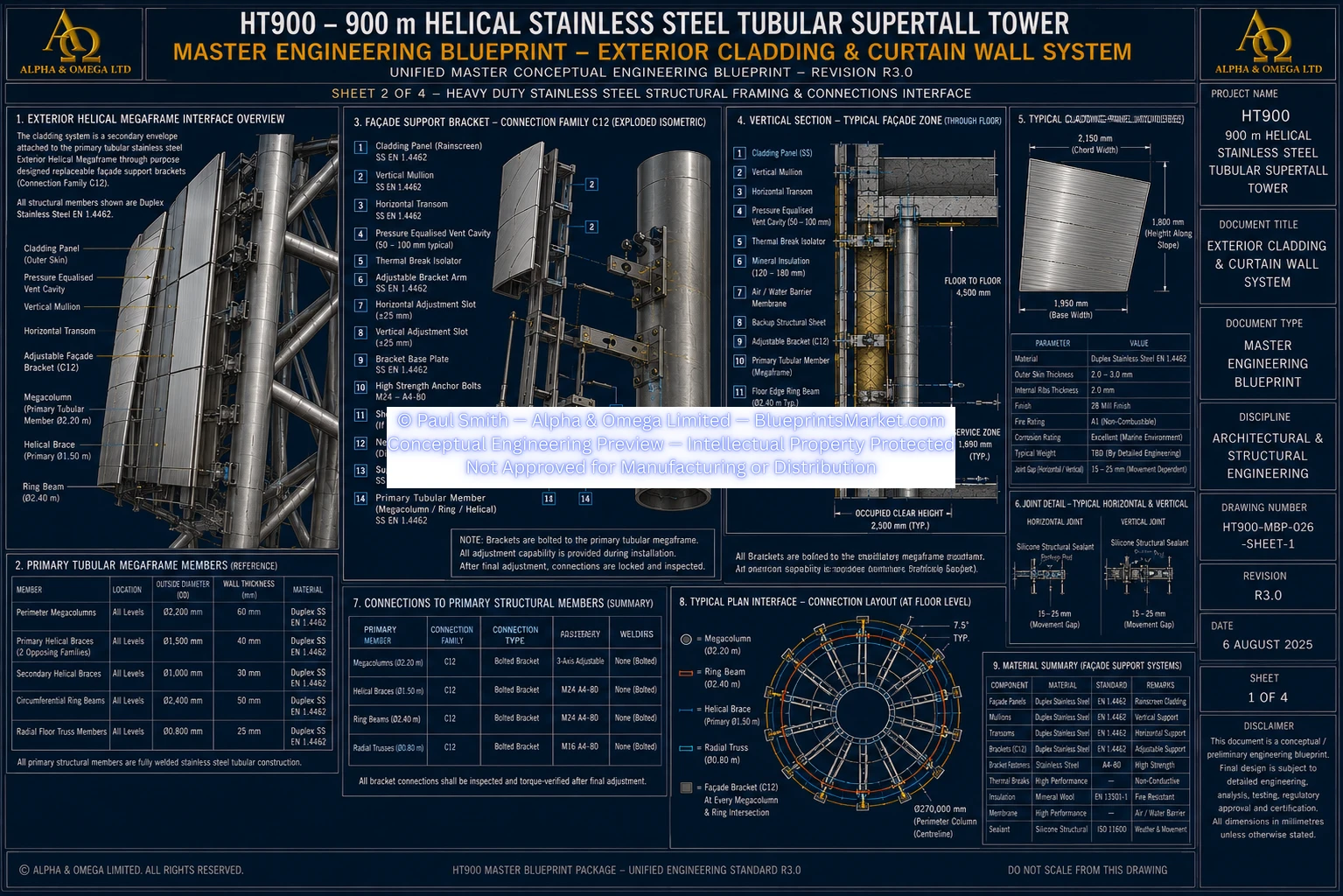
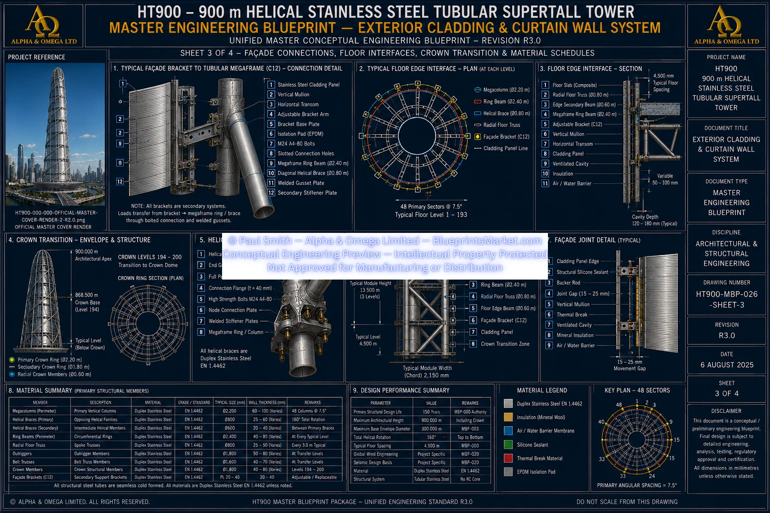
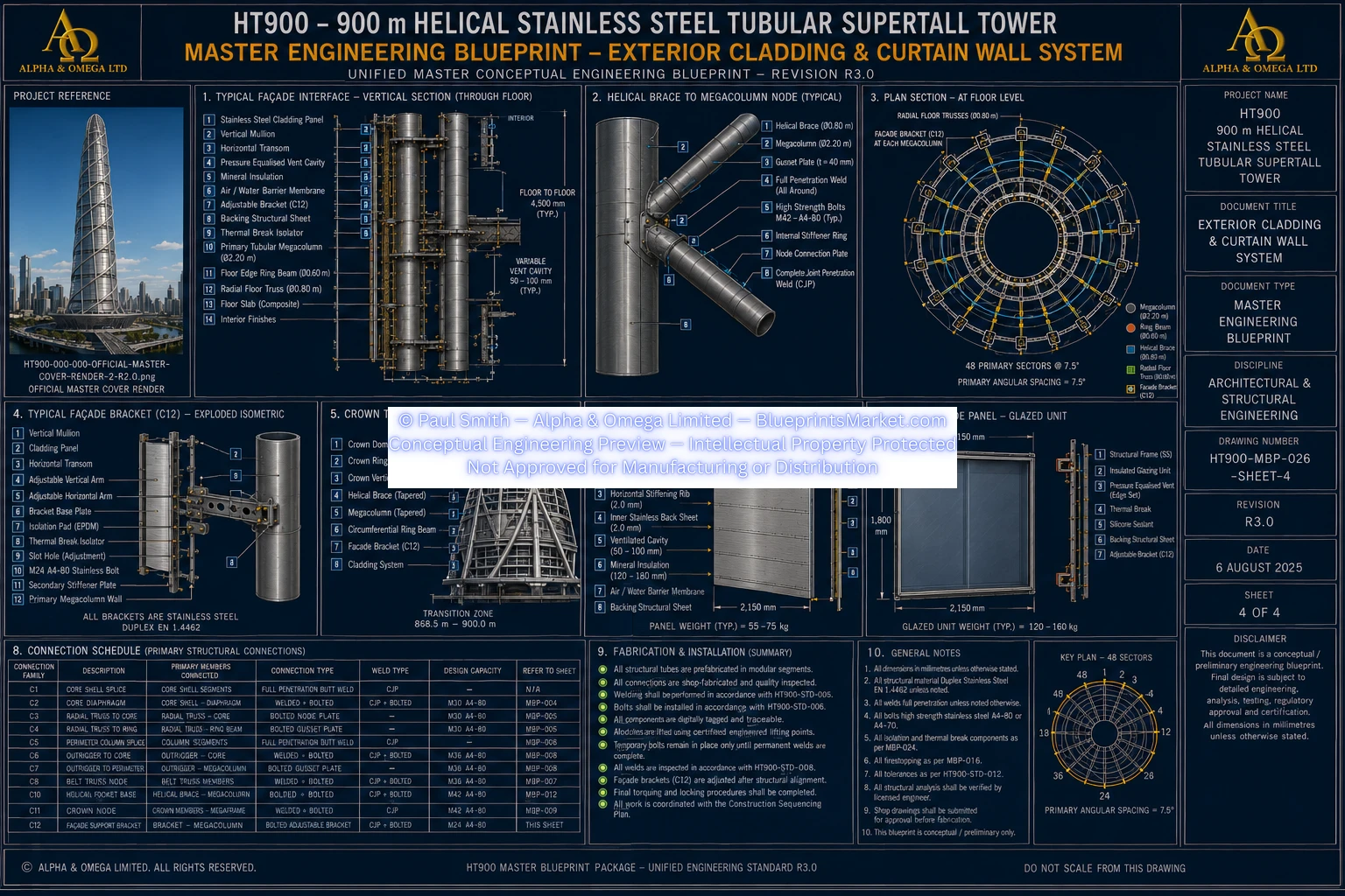
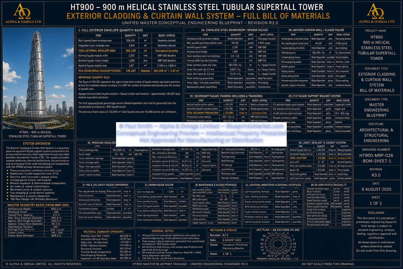
HT900-MBP-026 — Exterior Cladding & Curtain Wall System
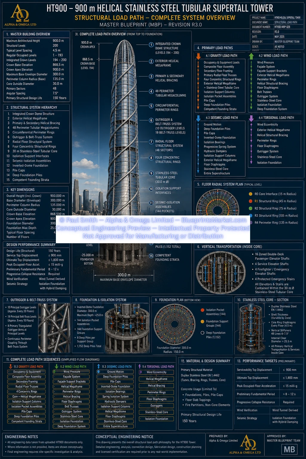
HT900-MBP-028 — Structural Load Path System
Copyright — Alpha & Omega Limited
All blueprint files, documented design parameters, architectural concepts, engineering specifications, and written content are the exclusive intellectual property of Alpha & Omega Limited. No part of the Stainless‑Steel Skyscraper Blueprint Package may be reproduced, distributed, or adapted without written consent.
Licensing, Copyright & Patent Restrictions
This engineering system and all associated blueprint materials, technical documents, diagrams, schematics, dimensional tables, and technical narratives are licensed, not sold, and remain the exclusive intellectual property of Alpha & Omega Limited.
This product is not eligible for patenting by any purchaser, user, organization, or third party. Patent filings, provisional patents, utility models, derivative patents, reverse‑engineering for patent purposes, and intellectual property claims are strictly prohibited.
Redistribution, resale, sublicensing, public posting, dataset inclusion, or any form of unauthorized duplication of blueprint materials, technical documents, diagrams, or engineering concepts is strictly prohibited. No license tier grants ownership, patent rights, or rights to file for intellectual property protection.
All architectural & engineering systems are conceptual and require full professional engineering validation before any real‑world use, construction, prototyping, or structural implementation.
Full legal details are available in the Terms & Conditions .