BLUEPRINTS MARKET • PREMIUM CONCEPT ENGINEERING PACKAGE
CCAMTG-2500 A04 — 2.5 MW-Class Dual-Mode Compressed-Air
Energy Storage / Recovery Magnetic Motor-Generator Machine
A complete concept-engineering package for an integrated dual-mode compressed-air
energy storage and recovery machine combining three-stage centrifugal compression,
thermal-energy recovery, external CAES integration, three-stage reheated turbine
expansion, active magnetic bearings, permanent-magnet motor-generator technology,
bidirectional power conversion, battery energy storage, industrial controls,
manufacturing engineering, quality assurance, commissioning and safety architecture.
2.50 MW Net AC Generation Target
Dual-Mode Energy Storage & Recovery
Three-Stage Compression
Three-Stage Reheated Expansion
Active Magnetic Bearings
Integrated Thermal-Energy Recovery
VIEW COMPLETE CCAMTG-2500-A04 MASTER BLUEPRINT & DOCUMENT LIBRARY
CCAMTG-2500 A04 — Main Public Specifications
Net AC Generation
2.50 MW
Public A04 generation design target.
Nominal Rotor Speed
12,000 rpm
Common high-speed rotor operating target.
Master Air Mass Flow
12.2 kg/s
Rated serial process-air flow.
Compression Range
1.20 bara → ~31 bara
Three-stage compressed-air charging architecture.
Expansion Range
~31 bara → 1.20 bara
Three-stage reheated energy-recovery architecture.
DC Power System
1,500 VDC
Nominal common DC power-conversion architecture.
BESS Energy Capacity
~5 MWh LFP
Battery-energy-storage design basis.
Dry Skid Mass
~22,000 kg
Estimated A04 machinery-skid mass basis.
One Integrated Machine — Two Energy Modes
The CCAMTG-2500 A04 is engineered around a dual-mode energy architecture.
Rather than treating compression, storage, thermal recovery, turbine expansion
and electrical generation as unrelated systems, the A04 package integrates them
around a common machine architecture with coordinated mechanical, pneumatic,
thermal, electrical and control interfaces.
In charge mode, electrical energy is converted into rotating mechanical power,
compressed-air energy and recoverable thermal energy. In generation mode,
previously stored compressed air and available thermal energy are returned through
the machine to produce shaft power and electrical generation.
Dual-Mode Operating Architecture
Charge Mode — Store Energy
The PMSM/PMG operates as a high-speed motor, driving the common rotor
and three-stage centrifugal compressor.
- Electrical energy enters through the grid and/or BESS power-conversion path.
- The bidirectional converter operates the PMSM/PMG in motor mode.
- The common rotor drives the three-stage centrifugal compressor.
- Conditioned air is progressively compressed through three serial stages.
- Intercooling removes compression heat between stages.
- Recoverable thermal energy is transferred toward the TES system.
- Final compressed air passes through cooling and the HP buffer.
- Compressed air is transferred to the external CAES storage system.
Generation Mode — Recover Energy
Stored compressed air is returned through the machine and expanded
through a thermally supported three-stage turbine train.
- Compressed air returns from the external CAES storage system.
- High-pressure air passes through controlled isolation and the HP buffer.
- Available stored thermal energy preheats the turbine inlet flow.
- Air expands through turbine Stage 1.
- Thermal energy reheats the air before Stage 2.
- A second reheat supports Stage 3 expansion.
- Turbine shaft power drives the common rotor and PMG.
- Electrical energy passes through active rectification and the common DC system.
- Recovered electrical energy can be routed toward the BESS and/or grid interface.
Complete Energy-Flow Architecture
Charge Energy Path
Grid / BESS → Bidirectional Power Conversion → PMSM Motor →
Common Rotor → Three-Stage Compressor → Intercooling →
Thermal-Energy Recovery → HP Buffer → External CAES Storage
Generation Energy Path
External CAES Storage → HP Buffer → Thermal Preheat →
Three-Stage Reheated Turbine → Common Rotor → PMG →
Active Rectifier → 1,500 VDC Bus → BESS / Grid Interface
Major Engineering Highlights
Three-Stage Centrifugal Compression
A serial three-stage compressor architecture provides progressive
pressure rise from the conditioned inlet toward the high-pressure
compressed-air storage interface.
Three-Stage Reheated Turbine
Stored compressed air is expanded through three turbine stages with
thermal preheating and interstage reheating to support controlled
energy recovery.
Common High-Speed Rotor
Compressor, PMSM/PMG and turbine functions are mechanically integrated
around a common rotor architecture with controlled coupling,
alignment and rotor-dynamic interfaces.
Active Magnetic Bearings
Non-contact radial and axial magnetic-bearing support provides
controlled high-speed rotor positioning, supported by dedicated
sensing and control architecture.
Independent Touchdown Bearings
Independent mechanical touchdown bearings provide defined backup
rotor support for controlled fault and coast-down scenarios.
Thermal-Energy Recovery
Compression heat is intentionally captured through the intercooling
and aftercooling architecture for later use in turbine preheat and
interstage reheat.
Bidirectional Electrical Conversion
The electrical architecture supports both motor operation during
energy storage and generator operation during energy recovery through
a common bidirectional conversion platform.
Integrated BESS Architecture
A lithium iron phosphate battery-energy-storage basis is integrated
with the PCS, common DC system, machine controls and grid interface.
Industrial Control Architecture
PLC, SIS, HMI and SCADA systems coordinate operating modes,
permissives, interlocks, process control, alarms, trips,
machine protection and supervisory monitoring.
Structural Machinery Skid
The machine is organized around an integrated structural skid
providing machinery support, alignment interfaces, lifting,
transport and foundation load transfer.
Integrated Safety Architecture
Pressure protection, overspeed protection, compressor anti-surge,
AMB/TDB fault management, electrical isolation, fire detection,
guarding and controlled depressurization are integrated into the
concept-engineering safety basis.
Lifecycle Engineering
Manufacturing, QA/NDE, assembly, commissioning, maintenance and
lifecycle requirements are treated as part of the engineering
architecture rather than as afterthoughts.
Air Intake & Conditioning
The process begins with an engineered intake and conditioning subsystem
designed to deliver clean, measurable and controllable airflow to the
compressor inlet.
- External intake interface
- Filter-bank and housing architecture
- Filter differential-pressure monitoring
- Bellmouth inlet
- Optional acoustic treatment interface
- Condensate and moisture management
- Actuated inlet guide vane system
- Guide-vane position feedback
- Inlet pressure and temperature instrumentation
Three-Stage Centrifugal Compressor
The charge-mode compressor is a three-stage centrifugal architecture
operating in serial flow on the common rotor train.
- Three centrifugal compressor stages
- Three impeller assemblies
- Three diffuser systems
- Interstage return and flow passages
- Compressor casing architecture
- Discharge collector
- Labyrinth process sealing
- Anti-surge recycle architecture
- Map-based surge protection philosophy
- Integrated pressure, temperature, speed and airflow interfaces
Intercooling, Heat Recovery & TES Integration
Compression naturally produces heat. The A04 architecture does not
simply discard that thermal energy: staged heat exchangers remove heat
from the compressed-air stream and provide an interface for thermal-energy
recovery.
- Stage-1 compressor intercooling
- Stage-2 compressor intercooling
- Final aftercooling and heat recovery
- Thermal-energy-storage interface
- Turbine high-pressure preheater
- First turbine interstage reheater
- Second turbine interstage reheater
- Separate machine-cooling architecture
- Duty / standby cooling philosophy
- Thermal instrumentation and control interfaces
HP Buffer & External CAES Interface
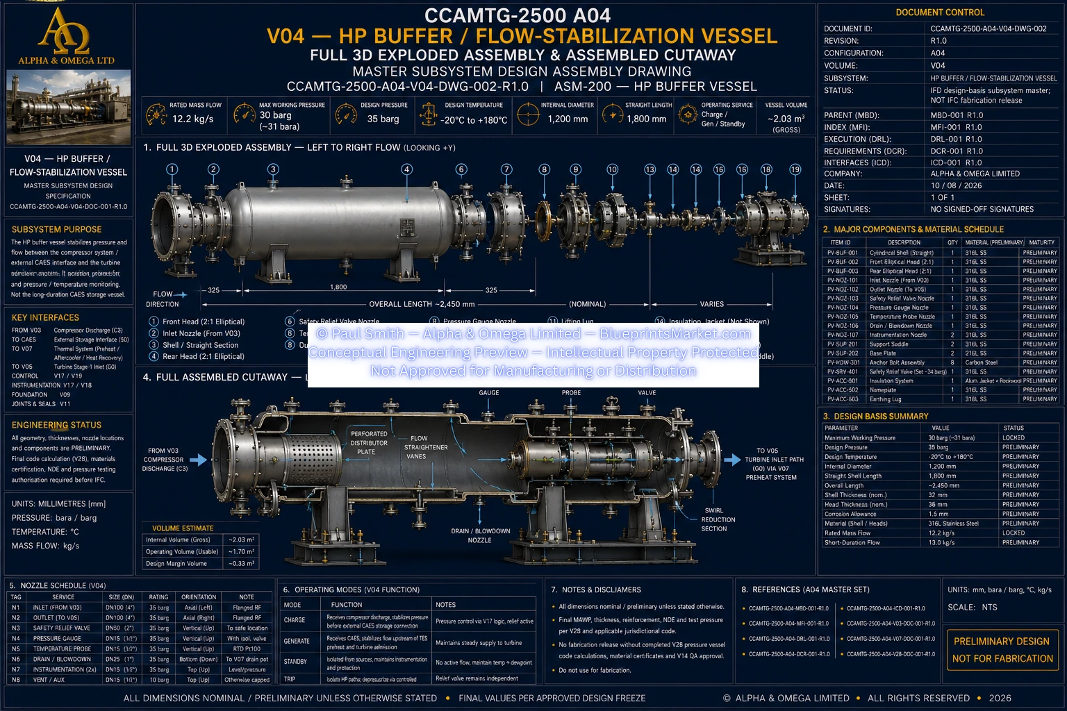
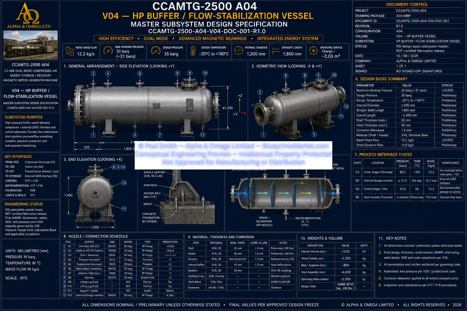
The local HP buffer is a flow-stabilization and transition component,
not the long-duration storage reservoir. Long-duration compressed-air
energy storage remains external and site-specific.
- Local high-pressure flow stabilization
- Charge-mode compressor discharge interface
- External CAES storage interface
- Generation-mode turbine admission interface
- Pressure and temperature instrumentation
- Fail-safe isolation philosophy
- Reverse-flow protection
- Independent mechanical overpressure protection
- Controlled depressurization and blowdown architecture
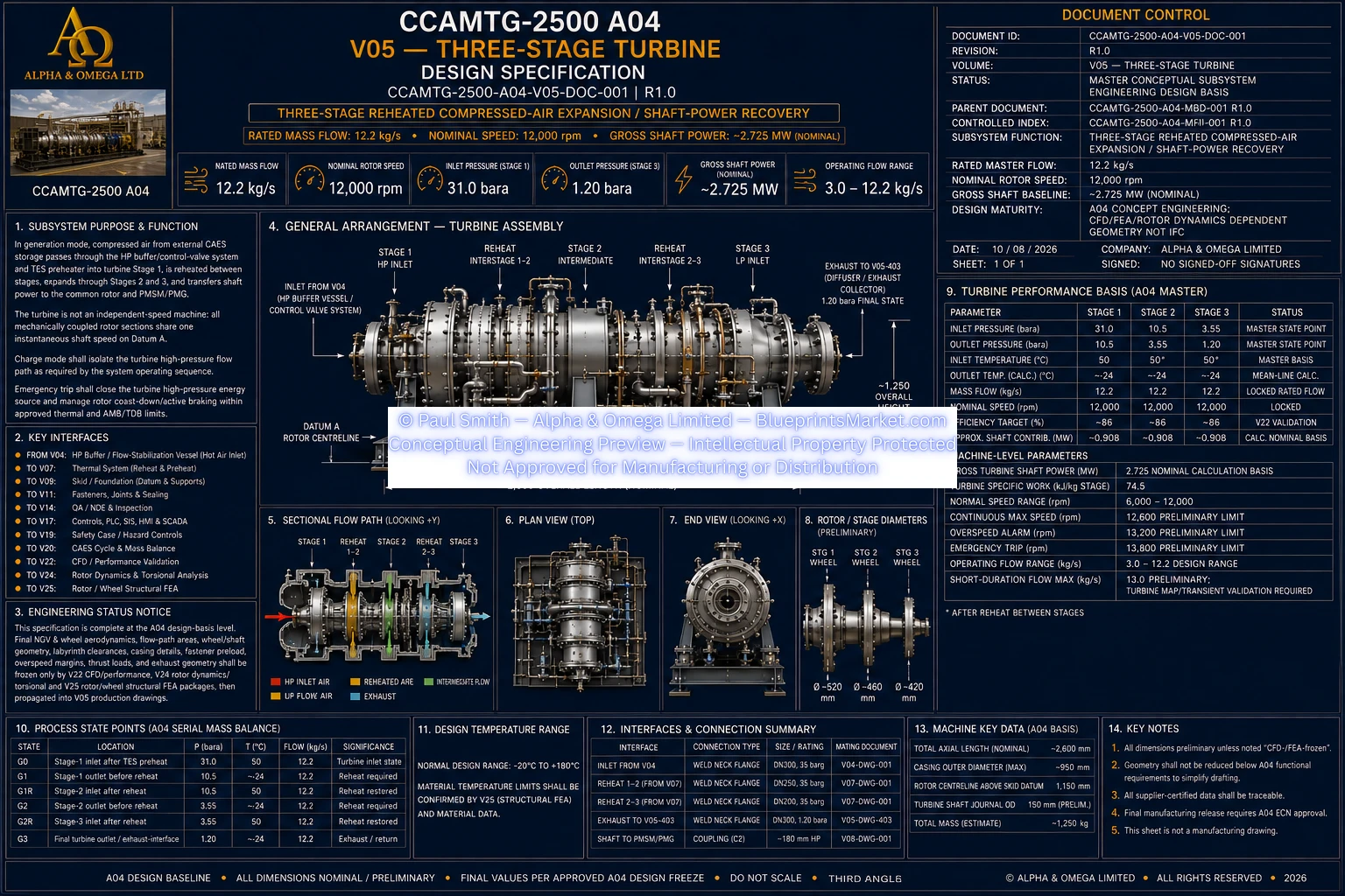
Three-Stage Reheated Turbine
Generation mode uses a three-stage compressed-air turbine designed around
controlled serial expansion and thermal restoration between expansion stages.
- Three turbine expansion stages
- Dedicated nozzle guide vane architecture
- Dedicated turbine wheel assemblies
- High-pressure turbine preheating
- Interstage reheat between Stage 1 and Stage 2
- Interstage reheat between Stage 2 and Stage 3
- Labyrinth sealing architecture
- Diffuser and exhaust collection
- Rotor-speed and vibration monitoring
- Controlled turbine admission
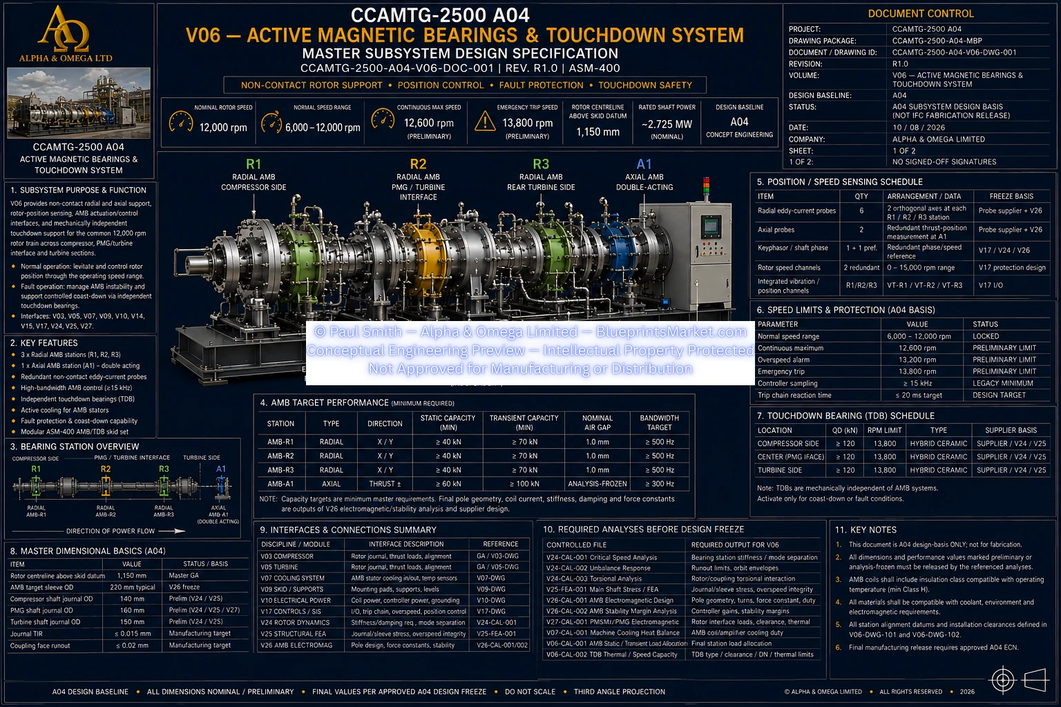
Active Magnetic Bearings & Touchdown Protection
The common high-speed rotor is supported during normal operation by
non-contact magnetic-bearing technology rather than conventional
continuously loaded mechanical bearings.
- Multiple radial active magnetic-bearing stations
- Double-acting axial magnetic-bearing architecture
- Continuous radial rotor-position sensing
- Axial position sensing
- Rotor speed and phase measurement
- Dedicated AMB controller and power amplifiers
- Levitation established before high-speed rotation
- Independent touchdown-bearing assemblies
- Controlled coast-down strategy during defined fault conditions
Permanent-Magnet Motor-Generator & Electrical Conversion
At the centre of the dual-mode architecture is a high-speed
permanent-magnet synchronous motor-generator capable of performing
two fundamentally different energy-conversion roles.
Motor Function
During charging, the PMSM/PMG converts electrical energy into shaft
torque to drive the compressor.
Generator Function
During energy recovery, turbine shaft power drives the same machine
in generator mode and transfers electrical energy through the
bidirectional conversion system.
- Permanent-magnet synchronous motor-generator
- Motor operation during compressed-air charging
- Generator operation during compressed-air energy recovery
- Active rectifier / motor-inverter architecture
- Common 1,500 VDC power backbone
- Precharge and electrical isolation
- Continuous insulation monitoring
- Bidirectional PCS
- BESS interface
- Grid inverter, transformer and switchgear interface
- Electrical metering and protection
Battery Energy Storage & Grid Integration
The A04 electrical architecture incorporates a common DC platform
capable of coordinating the motor-generator, bidirectional PCS,
LFP battery-energy-storage system and site grid connection.
- ~5 MWh LFP public BESS design basis
- Bidirectional battery charging and discharge
- BMS operating and safety interface
- State-of-charge supervision
- Available power-limit exchange
- Grid import and export architecture
- Energy-management interface
- Electrical isolation and protection
- Battery thermal and fire-status interfaces
PLC, SIS, HMI & SCADA Controls
The machine-level control architecture coordinates the pneumatic,
mechanical, thermal and electrical subsystems while maintaining
independent protection where required.
- Main deterministic machine PLC
- Independent SIS / safety layer where required
- Local HMI
- SCADA and historian interface
- Operating-state management
- Startup permissives
- Machine interlocks
- Alarm and trip architecture
- Cause-and-effect logic
- Anti-surge control coordination
- AMB controller integration
- PCS and BMS integration
- Valve command and position monitoring
- Machine data acquisition
- Configuration and software change control
Controlled Machine Operating States
- Off / Isolated
- Control Power On
- Standby
- Magnetic-Bearing Levitation
- DC Precharge
- Charge Start
- Charge Run
- Generation Start
- Generation Run
- Controlled Stop
- Trip / Emergency
- Maintenance State
Integrated Safety Case & Hazard Controls
A04 incorporates a dedicated system safety architecture covering
pneumatic, rotating, electrical, battery, thermal and maintenance
energy hazards.
Pressure Protection
Independent mechanical overpressure protection and controlled
high-pressure isolation are fundamental design requirements.
Compressor Protection
Anti-surge protection uses process measurements and a protective
recycle architecture designed to move toward a safe state.
Rotor Protection
Redundant rotor-speed sensing, vibration monitoring, AMB fault
management and touchdown support form the high-speed rotor
protection architecture.
Electrical Protection
Electrical isolation, insulation monitoring, earthing,
protection coordination and stored-energy control are integrated
into the machine design basis.
BESS Safety
Battery-management authority, thermal monitoring, fire detection
and controlled electrical isolation are incorporated at system level.
Maintenance Safety
Controlled zero-energy isolation, depressurization, zero-speed
verification and lockout/tagout form the basis for intrusive service.
Structured Hazard Engineering
The package does not stop at generic safety statements. Its safety
architecture is organized around recognized engineering study methods
and controlled verification requirements.
- Integrated Safety Case
- HAZOP architecture
- System FMEA / FMECA
- LOPA / SIL determination basis
- Emergency-response architecture
- Safe-state philosophy
- Safety action and recommendation control
- Cross-volume safety traceability
- FAT / SAT safety verification requirements
Structural Skid & Foundation Interface
The complete machinery train is organized around an integrated
structural skid that carries the rotating equipment, pressure equipment,
thermal hardware, controls and auxiliary equipment while maintaining
alignment and installation interfaces.
- Integrated welded machinery skid
- Machinery mounting and support architecture
- Common rotor datum integration
- Machined support and alignment interfaces
- Lifting and transport provisions
- Foundation load transfer
- Grout interface
- Site-specific anchor interface
- Equipment guarding
- Grounding and bonding attachment provisions
Fasteners, Joints & Sealing Integrity
Critical connections are treated as engineered joints rather than
generic hardware selections.
- Critical bolted-joint identification
- Joint-specific preload engineering
- Pressure-flange and gasket architecture
- Compressor and turbine casing joints
- Bearing and machinery housing joints
- Rotating-component retention
- Structural mounting joints
- Static and dynamic sealing
- Joint inspection and traceability
- Controlled installation and reuse rules
Manufacturing Engineering
The package extends beyond conceptual machine arrangement into
manufacturing-process architecture for the principal mechanical,
rotating, pressure-containing, electrical and structural component families.
- Manufacturing process planning
- Fabrication routing
- Precision machining strategy
- Multi-axis machining requirements
- Welding qualification requirements
- Heat-treatment requirements
- Tooling and fixturing
- Rotor balancing architecture
- Dimensional metrology
- Cleanliness and contamination control
- Manufacturing traceability
- Preservation between manufacturing operations
- Nonconformance and engineering-change control
QA, Inspection & Non-Destructive Examination
Quality-control requirements extend from incoming material through
fabrication, assembly, testing and final machine release.
- Quality Plan / Inspection & Test Plan
- Incoming material inspection
- Material heat / lot / serial traceability
- Weld inspection
- Visual testing
- Liquid penetrant testing
- Magnetic particle testing where applicable
- Ultrasonic testing
- Radiographic testing where required
- Dimensional metrology
- Rotating-equipment quality release
- Pressure-boundary verification
- Electrical and instrumentation testing
- Calibration control
- Nonconformance and corrective-action control
- Manufacturing data-record closeout
Assembly & Installation Engineering
The A04 documentation includes controlled factory-build and site-installation
methodology so that the machine architecture remains coherent through
physical assembly and installation.
- Factory assembly sequencing
- Rotor-module installation
- Compressor installation
- PMSM/PMG installation
- Turbine installation
- AMB and touchdown-bearing installation
- High-speed coupling installation
- Rotor alignment methodology
- Thermal and cooling equipment installation
- HP buffer installation
- Electrical and controls integration
- Foundation and grout interface
- Lifting and transport controls
- Preservation and storage procedures
- Mechanical-completion handover
Maintenance, Service & Lifecycle Engineering
Maintainability and lifecycle service are incorporated into the
engineering package rather than being left entirely to downstream development.
- Preventive-maintenance architecture
- Condition-based maintenance
- Compressor inspection
- Turbine inspection
- PMSM/PMG service
- AMB inspection and service
- Touchdown-bearing inspection
- High-speed coupling inspection
- Pressure-system maintenance
- Heat-exchanger and cooling maintenance
- Electrical and BESS service interfaces
- Controls and instrumentation maintenance
- Major overhaul methodology
- Special service tooling
- Return-to-service gates
- Lifecycle records and traceability
Commissioning & Performance Acceptance
The package defines how the machine progresses from completed installation
toward controlled first energization, levitation, rotation, charge-mode proving,
generation-mode proving and formal performance acceptance.
- Pre-commissioning readiness
- Mechanical-completion verification
- Electrical energization readiness
- Controls and SIS functional proving
- First AMB levitation
- First controlled rotor rotation
- Charge-mode commissioning
- Generation-mode commissioning
- Protective-function testing
- Mode-transition testing
- Rated performance testing
- Measurement and data-quality requirements
- Performance data reduction
- Commissioning punch-list control
- Formal acceptance and handover
Public A04 Performance Targets
Generation
2.50 MW Net AC Target
Rated Rotor Speed
12,000 rpm
Rated Airflow
12.2 kg/s
Compression
1.20 bara → ~31 bara
Expansion
~31 bara → 1.20 bara
DC Architecture
1,500 VDC
What the CCAMTG-2500 A04 Engineering Package Contains
The current controlled Master File Index lists 117 files across the
CCAMTG-2500 A04 package, bringing the principal machine architecture,
subsystem engineering and lifecycle engineering into one organized
conceptual design package.
Master System Documentation
- Master Blueprint Document
- Master File Index
- Master Interface Control Document
- Master system-interface architecture
- Master blueprint sheets
- Official master cover renderings
General Arrangement
- General Arrangement design specification
- Datum-control architecture
- Multi-sheet GA drawings
- Subsystem location and interface control
Mechanical & Process Engineering
- Air intake and conditioning
- Three-stage compressor
- HP buffer vessel
- Three-stage turbine
- Active magnetic bearings
- Touchdown-bearing system
- Thermal and cooling systems
- Structural skid and foundation interface
Electrical & Controls Engineering
- Electrical power conversion
- Motor-generator integration
- 1,500 VDC architecture
- BESS and PCS interfaces
- PLC / SIS architecture
- HMI / SCADA architecture
- Alarm and trip philosophy
- Cause-and-effect architecture
Detailed Engineering Drawings
- Subsystem blueprint sheets
- Exploded assembly views
- Cutaway views
- System architecture sheets
- Full-machine exploded assembly
- Parts-identification drawings
Manufacturing & Quality
- Manufacturing engineering
- Fabrication-process planning
- Machining and heat-treatment architecture
- Welding qualification requirements
- QA / Inspection / NDE
- Material traceability
- Manufacturing data-record requirements
Assembly & Lifecycle
- Factory assembly engineering
- Rotor alignment methodology
- Site installation engineering
- Preservation and shipping
- Maintenance and service lifecycle
- Major overhaul architecture
- Return-to-service controls
Verification & Safety
- Commissioning architecture
- Performance-test methodology
- Protective-function testing
- Integrated Safety Case
- HAZOP framework
- FMEA / FMECA framework
- LOPA / SIL basis
- Emergency-response architecture
More Than a Single Blueprint
The CCAMTG-2500 A04 package is not presented as one isolated machine image.
Its value lies in the relationship between the documents: the master
architecture establishes the baseline, subsystem volumes develop each
engineering discipline, interface documents reconcile the boundaries,
manufacturing and QA documents define downstream engineering controls,
and commissioning and safety documents define how the integrated machine
is ultimately verified.
- System-level architecture
- Subsystem-level engineering
- Cross-subsystem interface control
- Mechanical and process engineering
- Electrical and control integration
- Manufacturing planning
- Inspection and traceability
- Assembly methodology
- Maintenance philosophy
- Commissioning methodology
- Safety and hazard-control engineering
Controlled A04 Engineering Baseline
One of the defining features of the A04 package is configuration control.
Master pressure, airflow, rotor speed, power, thermal state, electrical,
safety and interface values are governed from the master architecture
rather than being independently changed throughout unrelated documents.
- Master engineering hierarchy
- Controlled A04 baseline
- Cross-volume interface ownership
- Engineering Change Notice control
- Common rotor and datum architecture
- Mass and energy balance consistency rules
- Pressure-unit control
- Electrical rating verification rules
- Critical-joint engineering rules
- Analysis-dependent design-freeze controls
Why the A04 Architecture Matters
Complex machinery cannot be meaningfully represented by attractive
drawings alone. A compressor affects the thermal system. The thermal
system affects the turbine. The turbine affects the rotor. The rotor
affects the magnetic bearings. The motor-generator affects electrical
conversion and cooling. Controls must understand all of them, and safety
systems must remain effective across the entire operating envelope.
The A04 package is structured around these relationships. Mechanical,
pneumatic, thermal, electrical, structural, controls, manufacturing,
quality, commissioning and safety disciplines are treated as parts of
one integrated engineering baseline.
Engineering Maturity & Intended Status
The CCAMTG-2500 A04 is a real-world-based conceptual engineering baseline.
Its energy, pressure, airflow, rotor-speed, power architecture and principal
subsystem relationships are organized around physically consistent
engineering relationships.
It is not represented as a certified fabrication release. Final
aerodynamic geometry, high-speed rotor geometry, pressure-boundary
thicknesses, electromagnetic details, protection settings, site foundation
design, supplier-specific hardware and jurisdictional certification require
the applicable detailed analyses, certified supplier data and approvals
before manufacture.
Required Detailed Design-Freeze Disciplines Include
- Thermodynamic cycle modelling
- Compressor mean-line and CFD analysis
- Turbine mean-line and CFD analysis
- Heat-exchanger and TES modelling
- Rotor-dynamic analysis
- Torsional analysis
- Rotor and turbine-wheel structural FEA
- Skid and support structural FEA
- AMB electromagnetic and stability analysis
- PMSM/PMG electromagnetic design
- Pressure-vessel code calculations
- Electrical protection and short-circuit studies
- HAZOP / FMEA / LOPA safety studies
- Site foundation and structural engineering
Who This Engineering Package Is For
The CCAMTG-2500 A04 package is designed for purchasers seeking a
detailed conceptual reference for advanced compressed-air energy
storage and recovery machinery rather than a single simplified
illustration.
- Engineering concept development
- Compressed-air energy-storage research
- Industrial energy-recovery studies
- Mechanical system architecture studies
- Rotating-equipment concept development
- Thermal-energy recovery studies
- Power-conversion architecture studies
- Controls and automation planning
- Manufacturing-process planning
- QA and inspection planning
- Commissioning methodology development
- Engineering education and technical reference
What Makes the CCAMTG-2500 A04 Package Different?
Integrated Architecture
Compressor, turbine, rotor, magnetic bearings, thermal recovery,
BESS, grid conversion and controls are designed as one system architecture.
Dual Energy Path
The documentation covers both energy-storage charging and
energy-recovery generation rather than only one operating state.
Thermal Recovery Included
Compression heat is treated as an engineering resource with a
defined path into turbine preheat and reheat architecture.
Non-Contact Rotor Support
The common rotor architecture includes active magnetic-bearing
support with independent touchdown protection.
Lifecycle Coverage
Manufacturing, quality, installation, service, commissioning and
safety are represented alongside the primary machine design.
Controlled Engineering Status
Preliminary and analysis-dependent values remain explicitly
controlled rather than being falsely presented as certified
fabrication data.
CCAMTG-2500 A04 — Frequently Asked Questions
What is the CCAMTG-2500 A04?
It is a 2.5 MW-class dual-mode compressed-air energy-storage and
recovery magnetic motor-generator machine concept integrating
compression, thermal-energy recovery, external compressed-air storage,
turbine expansion, magnetic bearings, power conversion, BESS, controls
and machine protection.
What is the public generation target?
The A04 master engineering baseline identifies a net AC generation
target of 2.50 MW under the defined design conditions.
What is the nominal rotor speed?
The public A04 nominal common rotor-speed target is 12,000 rpm.
What is the rated airflow?
The master public process-air mass-flow target is 12.2 kg/s.
What pressure range does the architecture use?
The public compression architecture progresses from approximately
1.20 bara toward approximately 31 bara, with generation expansion
returning from approximately 31 bara toward 1.20 bara.
Does the machine create energy?
No. The CCAMTG-2500 A04 is an energy-storage and recovery architecture.
Charge mode consumes externally supplied electrical energy to create
stored pneumatic and thermal energy. Generation mode recovers a portion
of that stored energy as shaft and electrical output.
Is long-duration compressed-air storage built into the machine skid?
No. The local HP buffer supports flow stabilization and machine
transitions. Long-duration CAES storage is an external, site-specific system.
Does the design include thermal-energy recovery?
Yes. Compression heat is recovered through intercooling and aftercooling
interfaces and can support turbine preheating and interstage reheating
through the TES architecture.
Does the machine use active magnetic bearings?
Yes. The high-speed common rotor uses radial and axial active
magnetic-bearing support with independent mechanical touchdown-bearing
protection for defined fault conditions.
Does the package include electrical and control engineering?
Yes. The A04 package includes bidirectional power conversion,
the 1,500 VDC architecture, BESS and grid interfaces, PLC, SIS,
HMI, SCADA, machine I/O, alarms, trips and cause-and-effect architecture.
Does the package include manufacturing and QA information?
Yes. Manufacturing engineering, welding and machining architecture,
dimensional control, QA, inspection, NDE, material traceability and
manufacturing quality records form part of the controlled package.
Does the package cover commissioning?
Yes. Commissioning documentation covers pre-start readiness,
first energization, magnetic-bearing levitation, first rotation,
charge-mode proving, generation-mode proving, protection testing,
performance acceptance and handover methodology.
Is the package a certified fabrication release?
No. It is a detailed real-world-based concept-engineering baseline.
Final fabrication requires completion and approval of the applicable
CFD, FEA, rotor-dynamic, electromagnetic, pressure-code, electrical,
safety, supplier and site-specific design work.
CCAMTG-2500 A04 — Complete Concept Engineering Package
The CCAMTG-2500 A04 brings together compressed-air energy storage,
thermal-energy recovery, high-speed rotating machinery, active magnetic
bearings, permanent-magnet motor-generator technology, bidirectional
power electronics, battery storage, industrial automation,
manufacturing engineering, quality control, commissioning and
process-safety architecture into one coordinated engineering package.
It is designed as more than a visual blueprint set. It is a structured
conceptual engineering system in which the compressor, turbine, rotor,
electrical, thermal, structural, control and safety architectures are
connected through a controlled master design basis.
For purchasers studying advanced CAES machinery, industrial energy
recovery, magnetic-bearing rotating equipment or integrated
multi-discipline machine architecture, the CCAMTG-2500 A04 provides
a substantial technical reference extending from system concept through
manufacturing, installation, verification and lifecycle engineering.
Engineering Status Notice
CCAMTG-2500 A04 is a real-world-based conceptual engineering design baseline.
The package is not represented as a certified IFC fabrication release,
code-stamped pressure-equipment design, final site construction package
or jurisdictional approval. Final manufacture and installation require
completion and approval of all applicable detailed engineering analyses,
production drawings, supplier-certified data, pressure-code calculations,
electrical studies, hazard studies and site-specific engineering.
Intended Applications
- Advanced engineering research
- Mechanical engineering study
- Thermodynamic system analysis
- Compressed‑air system modelling
- Electrical generation research
- Heat‑pump and refrigeration studies
- Computational simulation
- CAD development
- Engineering education
- Concept evaluation and further design development
License & Usage
The CCAMTG‑2500 A04 Master Engineering Blueprint Package is licensed for engineering evaluation, research,
simulation, education, and internal development. All intellectual property, engineering concepts, CAD
drawings, schematics, documentation, and system architecture remain exclusively owned by Alpha & Omega
Limited.
Any physical implementation, prototyping, testing, manufacturing, or commercial deployment requires
independent engineering analysis, verification, certification, and regulatory approval by qualified
professionals in accordance with all applicable engineering standards and safety regulations.
Physical Construction Rights — One Unit, No Variations, Purpose-Locked Design
Unless expressly stated otherwise in the specific license accompanying a purchased blueprint package,
all BlueprintsMarket.com engineering blueprint products are licensed strictly for the construction of
one (1) single physical, real‑world unit of the system described in the purchased package.
This limitation applies universally to all current and future blueprint products, including conceptual,
mechanical, electrical, structural, thermal, CFD, and integrated system designs.
The purchaser is strictly prohibited from constructing, commissioning, fabricating, manufacturing,
assembling, reproducing, duplicating, mass‑producing, or creating any additional physical units,
derivative units, modified units, or functionally equivalent units without obtaining separate,
valid enterprise construction licenses for each additional unit. This prohibition includes any
variation, adaptation, redesign, or alternative implementation of the system that results in a
second physical build, regardless of scale, configuration, or intended use.
Engineering teams may make technical adjustments, refinements, or modifications solely for the
purpose of ensuring that each part, subsystem, or assembly functions correctly according to the
intended purpose, operational role, and conceptual design described in the blueprint package.
No part, subsystem, assembly, or section may be altered, redesigned, repurposed, or
re‑engineered for any function, application, or use other than the specific purpose expressly
defined within the blueprint documentation.
Any attempt to construct multiple units, derivative units, alternative‑purpose units, or
functionally similar units — including prototypes, test rigs, commercial units, industrial units,
municipal units, or research units — without the required additional enterprise licenses constitutes
a material breach of this agreement and a violation of the intellectual property rights of
Alpha & Omega Limited. No implied rights, inferred rights, engineering necessity, operational
requirement, or organizational need shall override or expand this limitation.
Construction of additional units requires the purchaser to obtain separate enterprise construction
licenses for each additional unit. Alpha & Omega Limited reserves the full legal right to enforce
these limitations through injunctive relief, damages, license termination, and permanent revocation
of access to all BlueprintsMarket products.
Legal & Engineering Notice
The CCAMTG‑2500 A04 Integrated Energy Generation & Thermal Management System is presented solely as a
conceptual engineering design. It has not been independently tested, certified, validated, or approved
for commercial, industrial, residential, or safety‑critical applications.
No representation or warranty is made regarding efficiency, energy production, electrical output,
thermal performance, cooling capacity, heating capability, operational reliability, manufacturability,
commercial viability, or real‑world performance. All specifications and calculations are conceptual
illustrations only.
Any physical implementation must be independently reviewed, analysed, engineered, validated, and
approved by qualified structural, mechanical, electrical, thermodynamic, refrigeration, and control
systems engineers together with all applicable regulatory authorities.
This blueprint package is intended for engineering research, conceptual study, education, simulation,
and design evaluation only and should not be interpreted as construction‑ready manufacturing
documentation.
Blueprint Package & Pricing
Includes the full conceptual engineering blueprint package, turbine architecture, generator integration,
thermal systems, and CAD‑ready documentation.
$8,995.00 USD
For detailed pricing and licensing options, visit the
Pricing page.
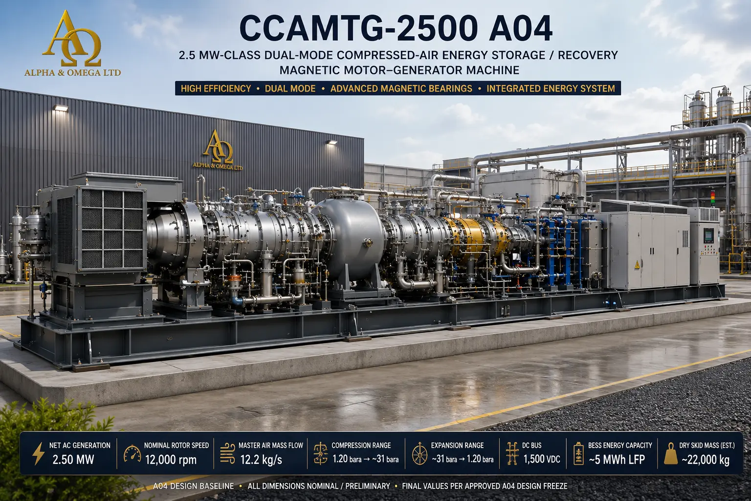
CCAMTG-2500 A04 — Official Master Cover Renders
© Paul Smith — Alpha & Omega Limited — PlatformClouds.com — Conceptual Engineering Preview — Not Approved for Manufacturing
© Paul Smith — Alpha & Omega Limited — PlatformClouds.com — Conceptual Engineering Preview — Not Approved for Manufacturing
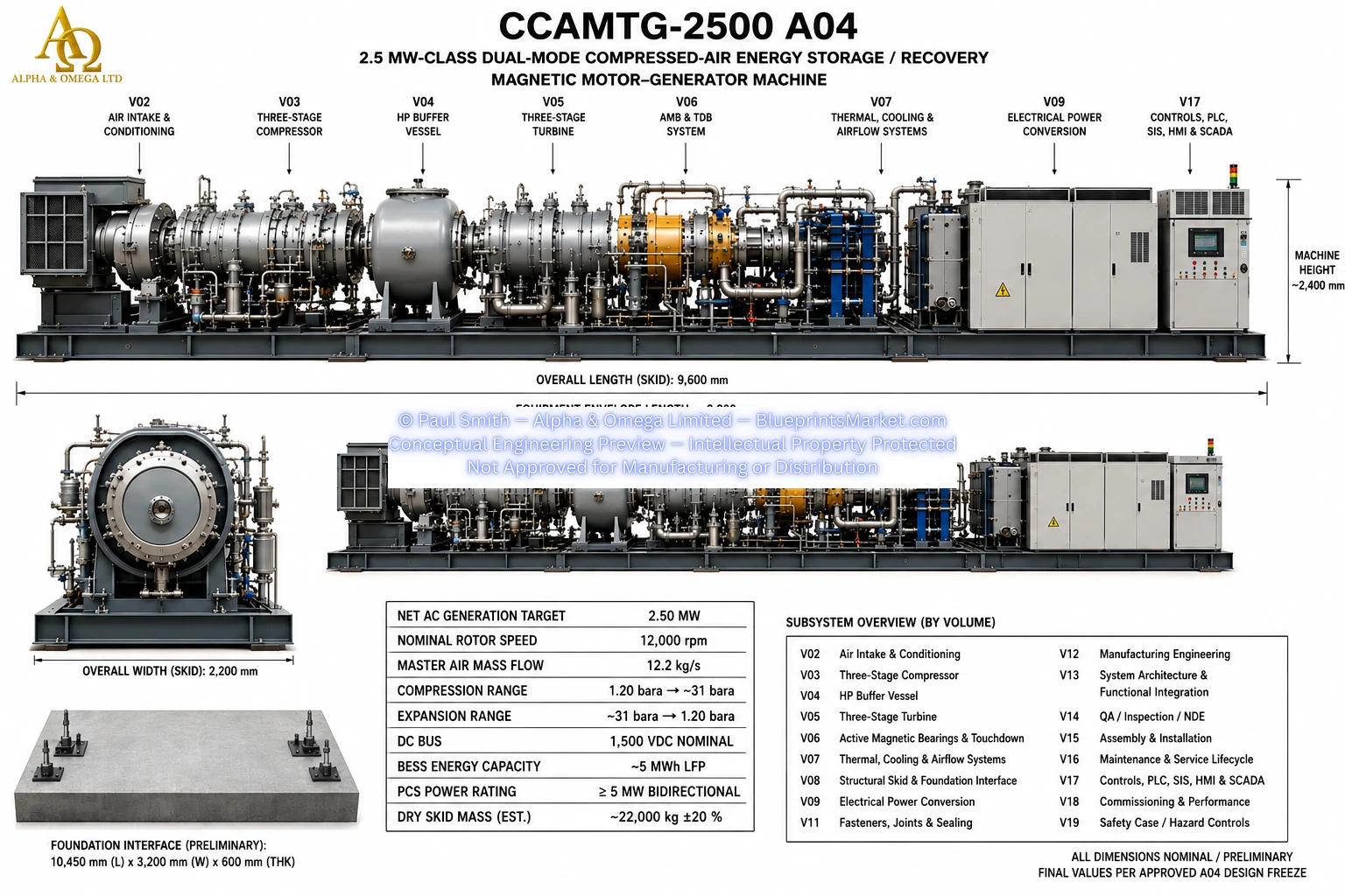
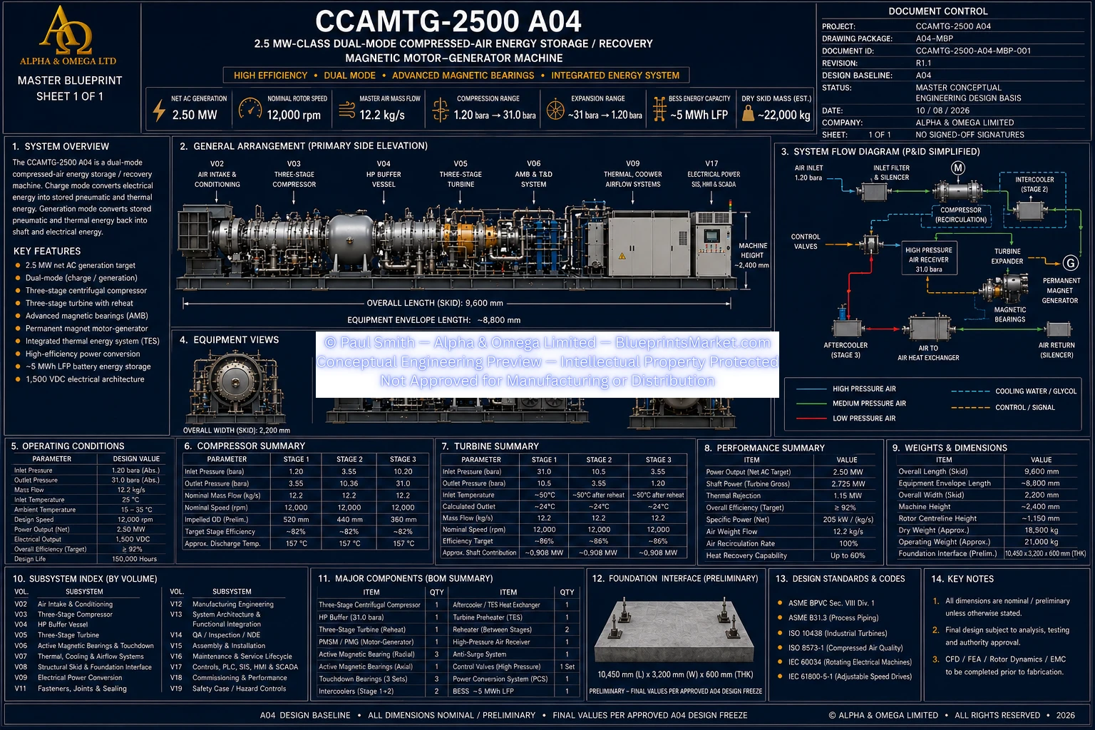
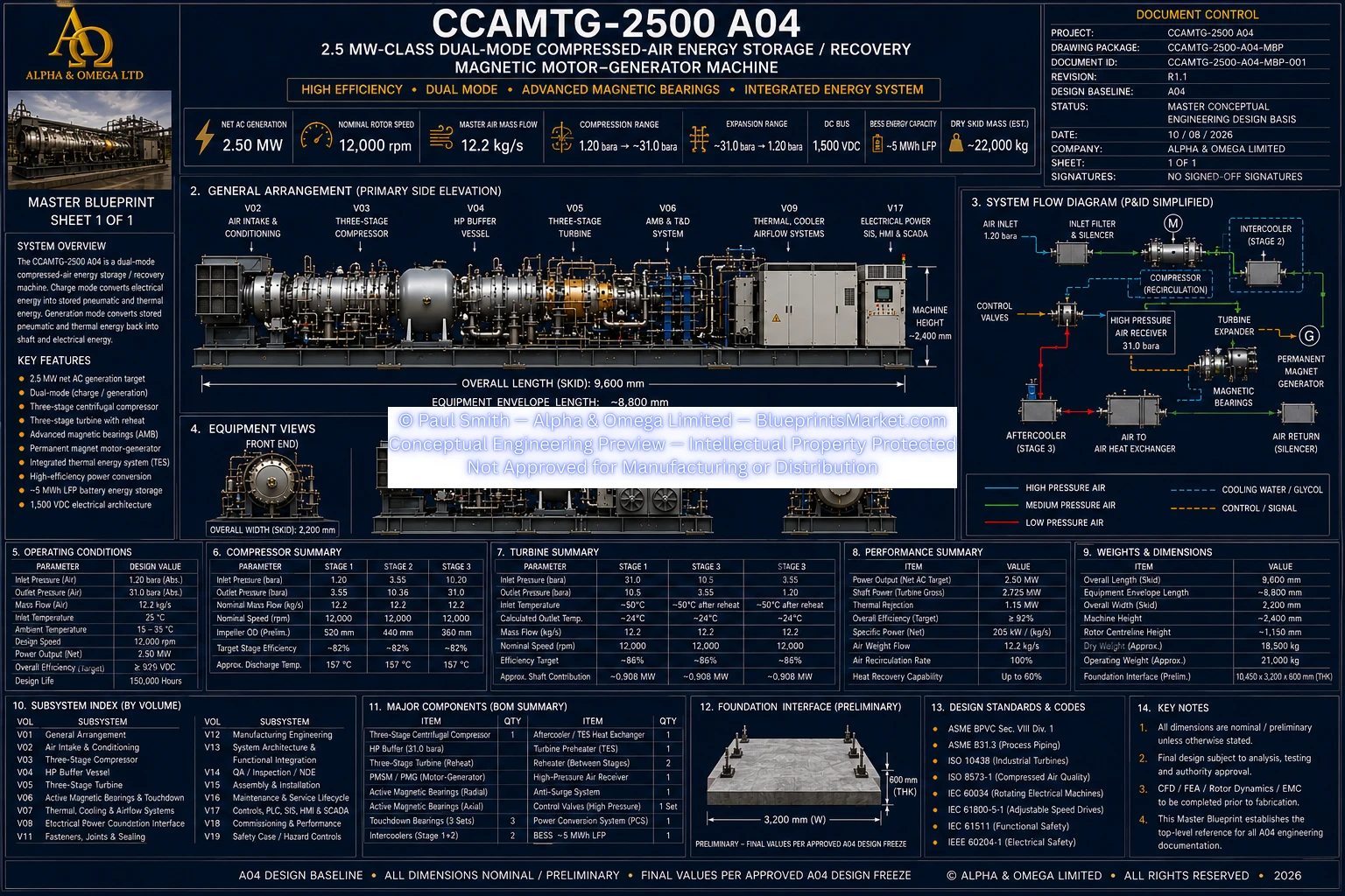
CCAMTG-2500 A04 — Master Blueprint
© Paul Smith — Alpha & Omega Limited — PlatformClouds.com — Conceptual Engineering Preview — Not Approved for Manufacturing
© Paul Smith — Alpha & Omega Limited — PlatformClouds.com — Conceptual Engineering Preview — Not Approved for Manufacturing
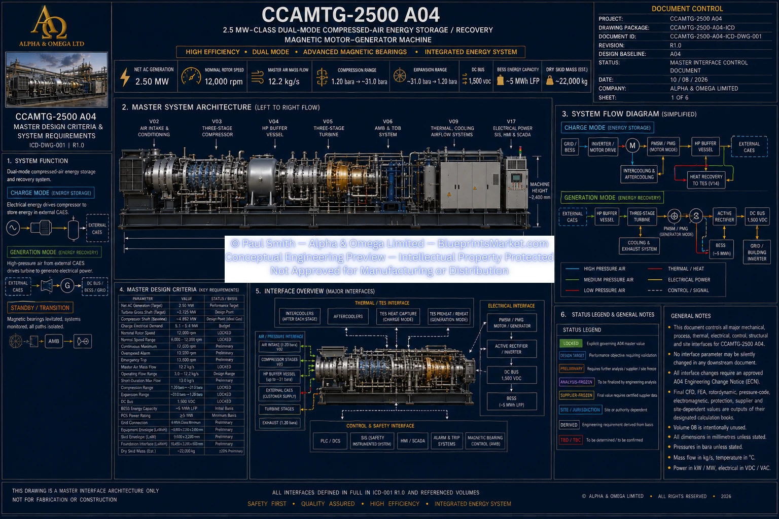
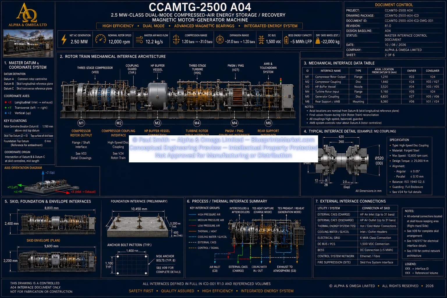
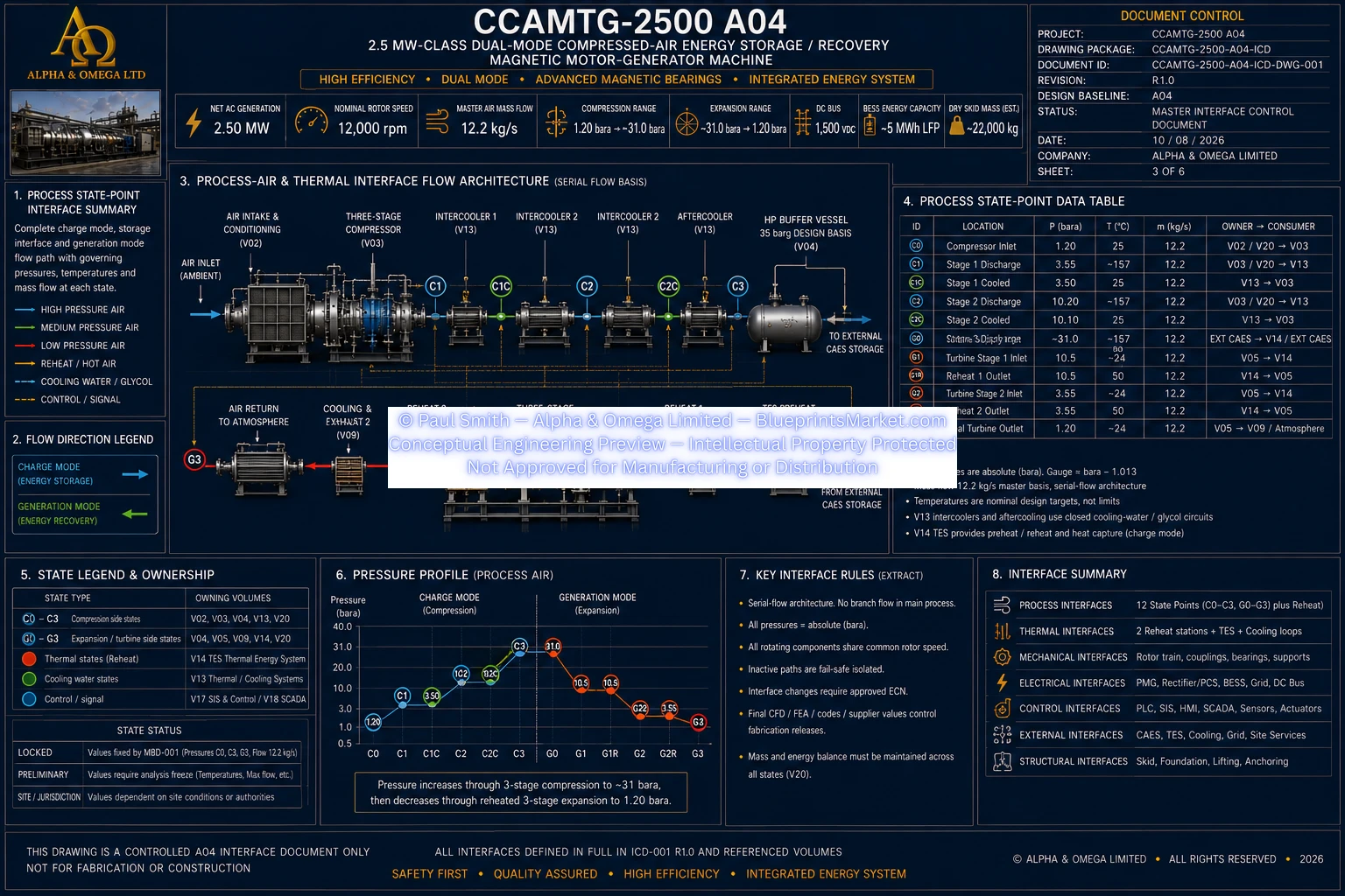
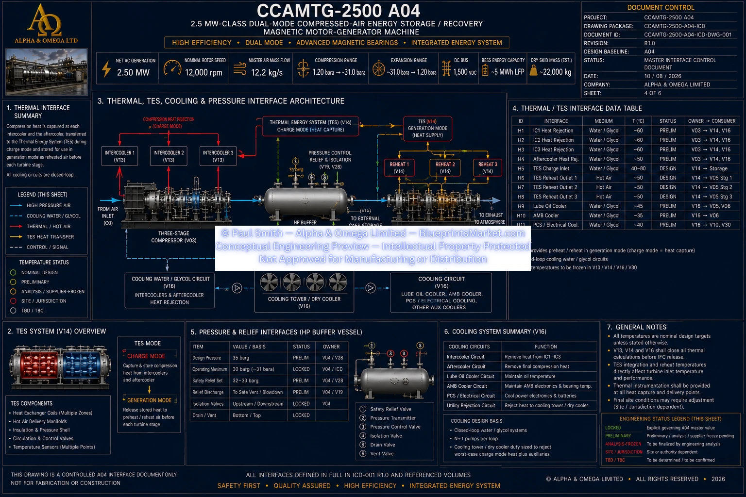
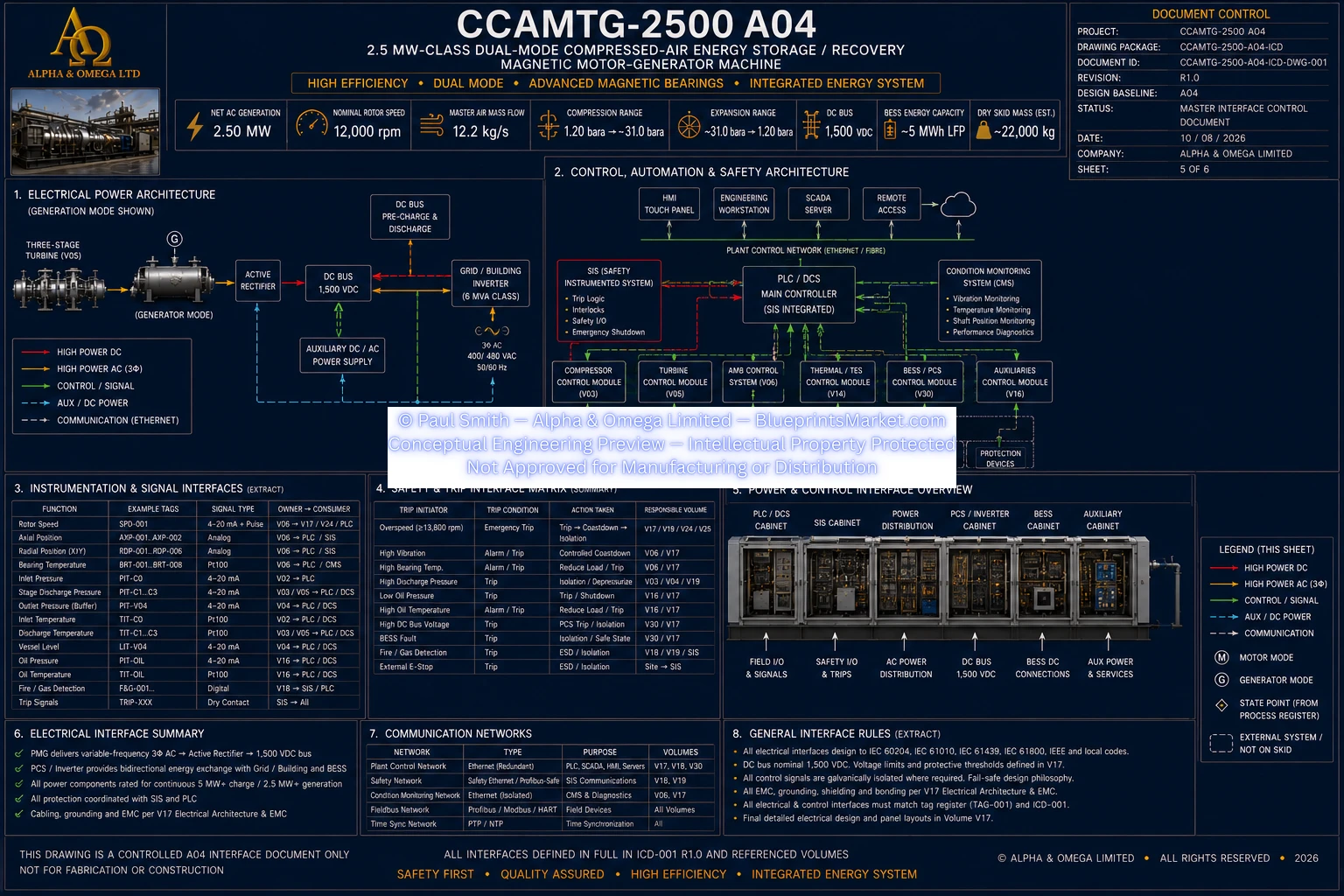
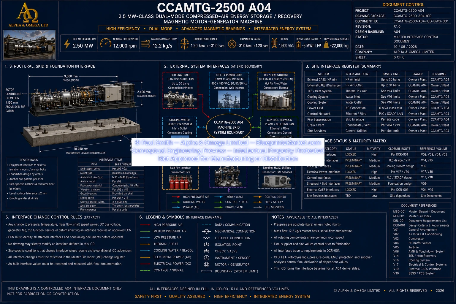
ICD — Master System Interface Architecture

© Paul Smith — Alpha & Omega Limited — PlatformClouds.com — Conceptual Engineering Preview — Not Approved for Manufacturing
© Paul Smith — Alpha & Omega Limited — PlatformClouds.com — Conceptual Engineering Preview — Not Approved for Manufacturing
© Paul Smith — Alpha & Omega Limited — PlatformClouds.com — Conceptual Engineering Preview — Not Approved for Manufacturing
© Paul Smith — Alpha & Omega Limited — PlatformClouds.com — Conceptual Engineering Preview — Not Approved for Manufacturing
© Paul Smith — Alpha & Omega Limited — PlatformClouds.com — Conceptual Engineering Preview — Not Approved for Manufacturing
© Paul Smith — Alpha & Omega Limited — PlatformClouds.com — Conceptual Engineering Preview — Not Approved for Manufacturing
© Paul Smith — Alpha & Omega Limited — PlatformClouds.com — Conceptual Engineering Preview — Not Approved for Manufacturing
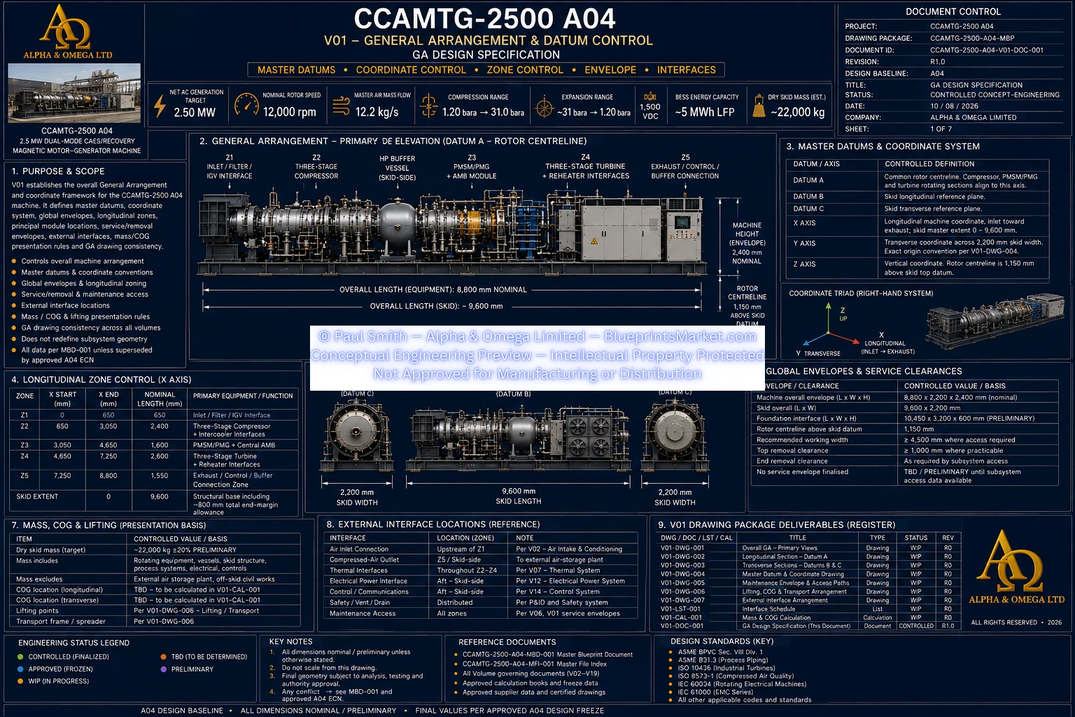
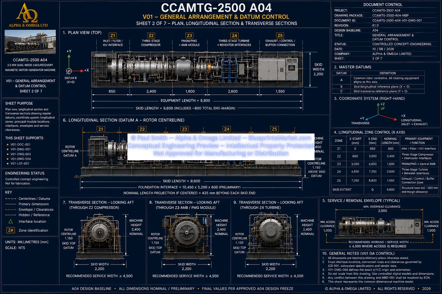
V01 — General Arrangement & Datum Control
© Paul Smith — Alpha & Omega Limited — PlatformClouds.com — Conceptual Engineering Preview — Not Approved for Manufacturing
© Paul Smith — Alpha & Omega Limited — PlatformClouds.com — Conceptual Engineering Preview — Not Approved for Manufacturing
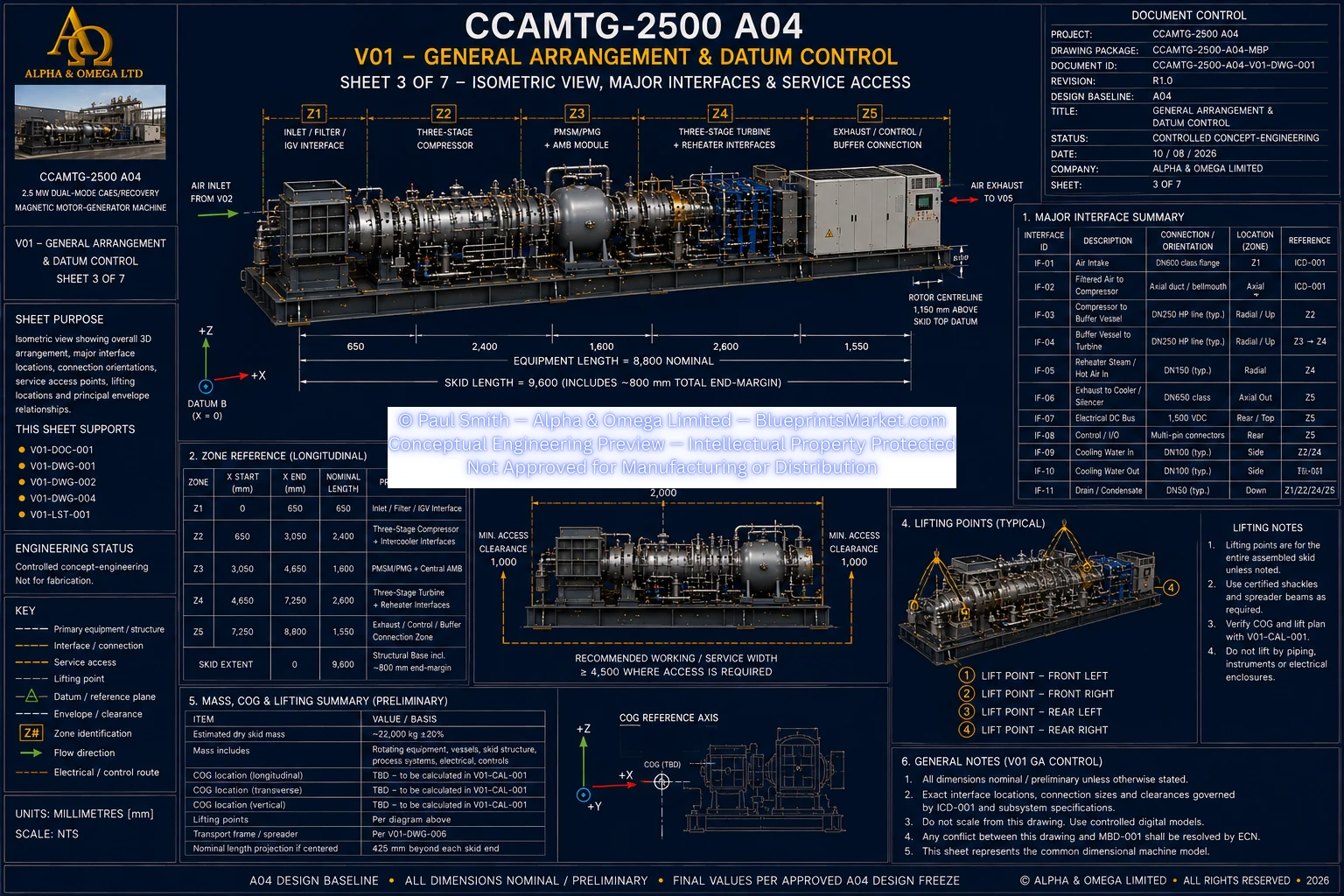
© Paul Smith — Alpha & Omega Limited — PlatformClouds.com — Conceptual Engineering Preview — Not Approved for Manufacturing
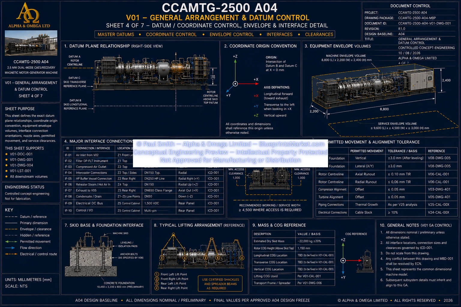
© Paul Smith — Alpha & Omega Limited — PlatformClouds.com — Conceptual Engineering Preview — Not Approved for Manufacturing
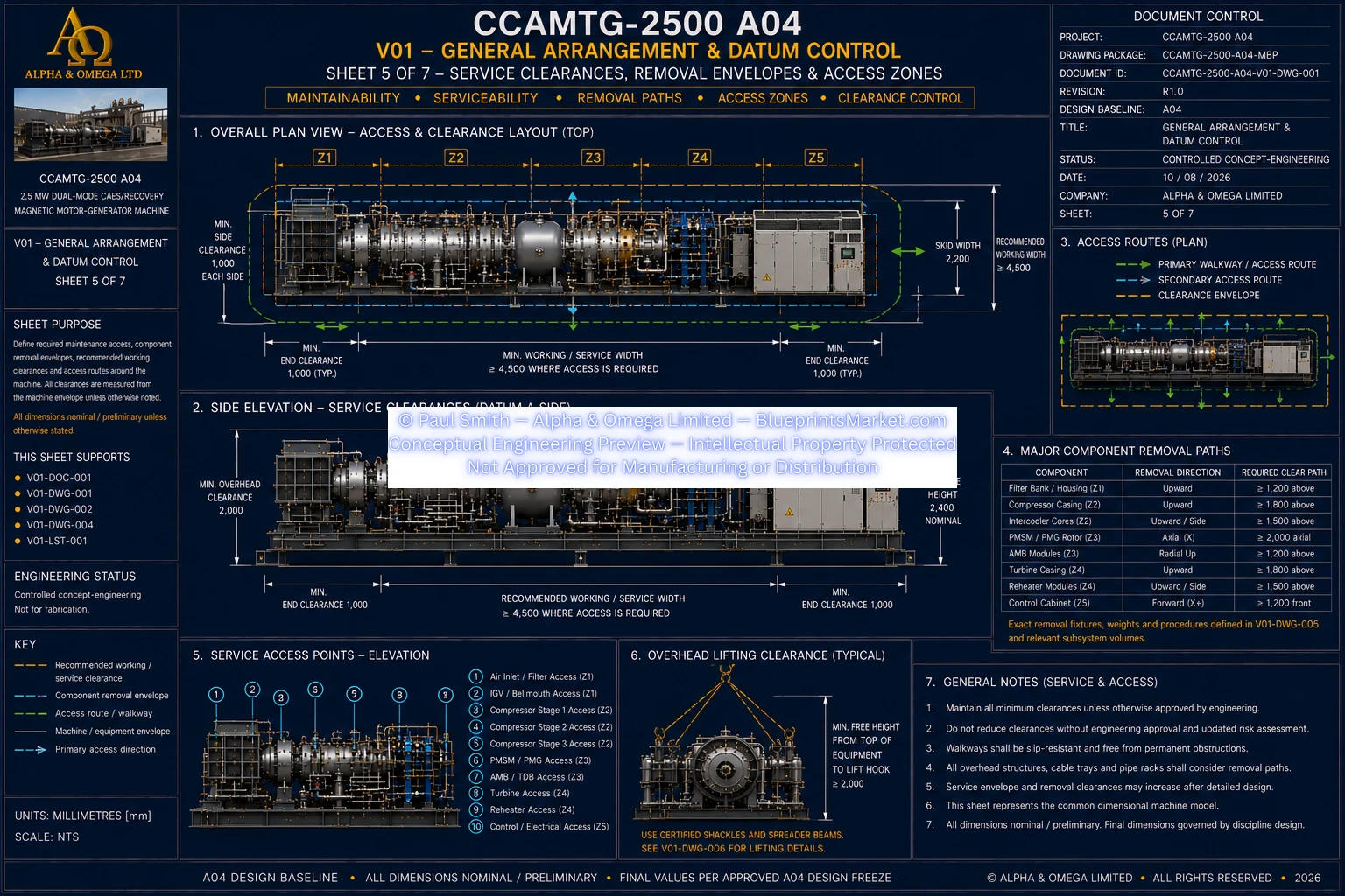
© Paul Smith — Alpha & Omega Limited — PlatformClouds.com — Conceptual Engineering Preview — Not Approved for Manufacturing
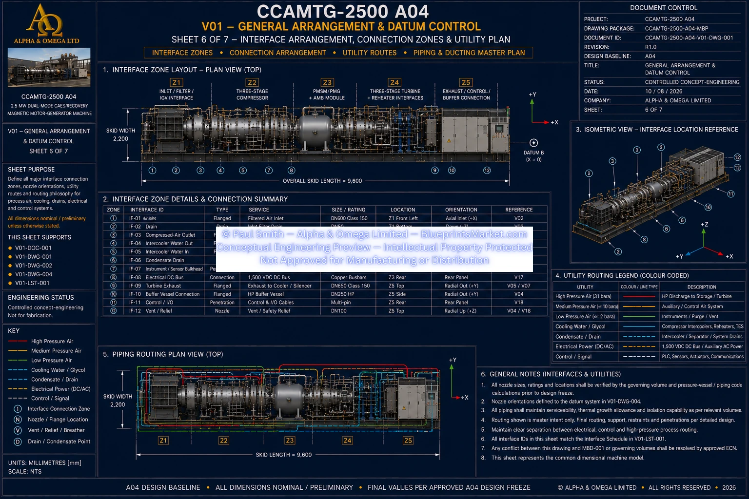
© Paul Smith — Alpha & Omega Limited — PlatformClouds.com — Conceptual Engineering Preview — Not Approved for Manufacturing
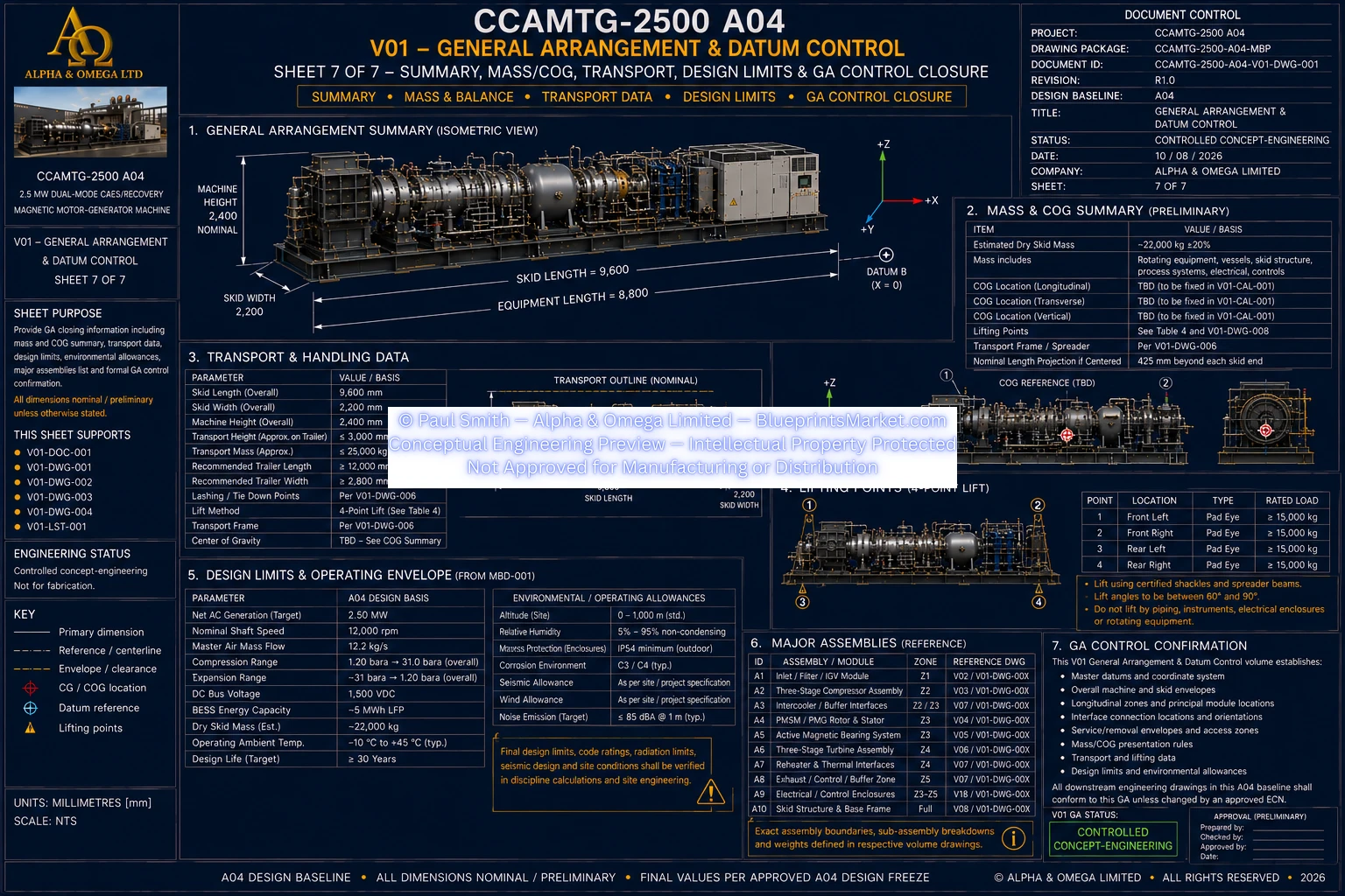
© Paul Smith — Alpha & Omega Limited — PlatformClouds.com — Conceptual Engineering Preview — Not Approved for Manufacturing
V02 — Air Intake & Conditioning
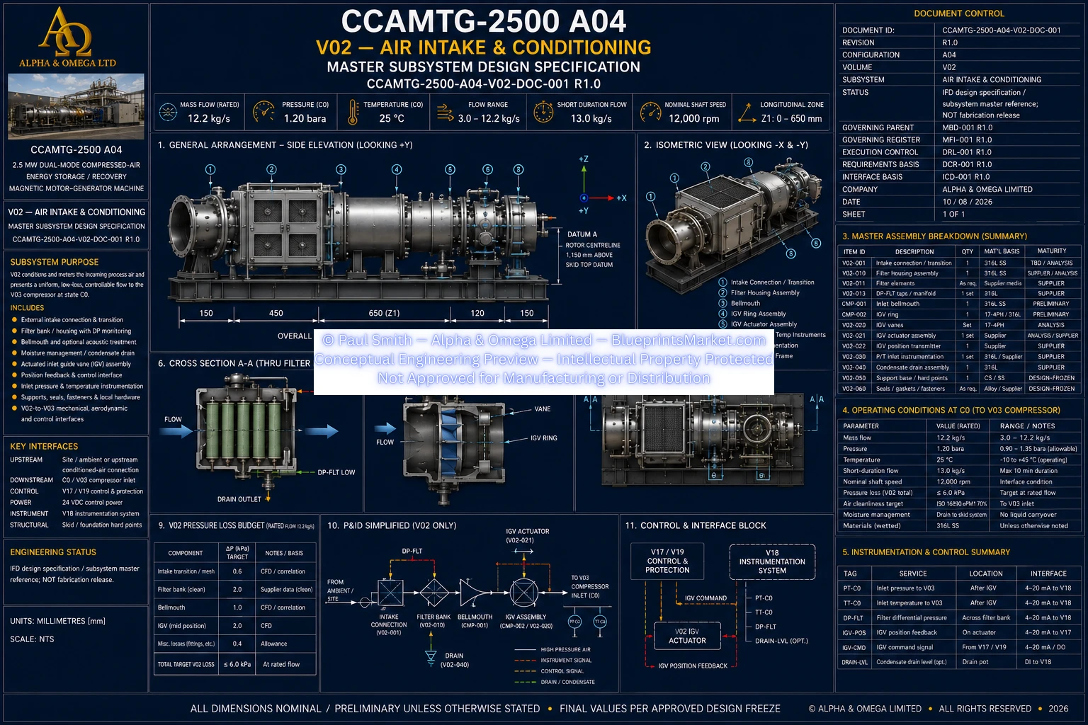
© Paul Smith — Alpha & Omega Limited — PlatformClouds.com — Conceptual Engineering Preview — Not Approved for Manufacturing
V03 — Three-Stage Centrifugal Compressor
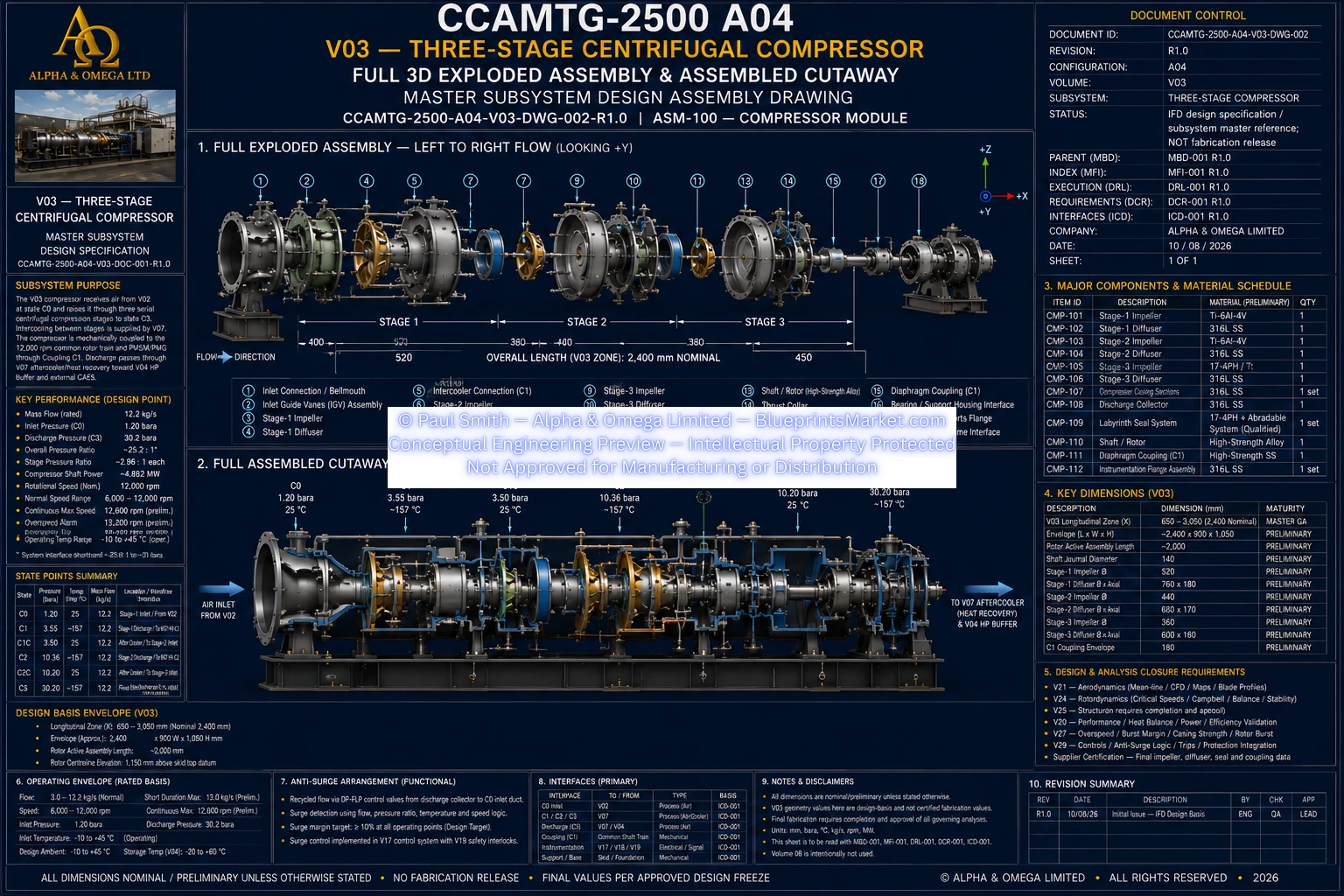
© Paul Smith — Alpha & Omega Limited — PlatformClouds.com — Conceptual Engineering Preview — Not Approved for Manufacturing
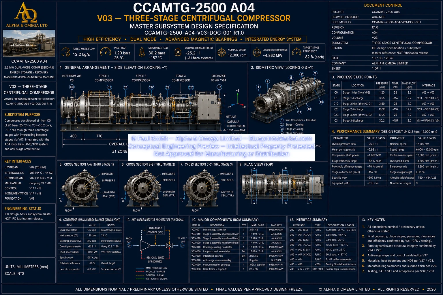
© Paul Smith — Alpha & Omega Limited — PlatformClouds.com — Conceptual Engineering Preview — Not Approved for Manufacturing
V04 — HP Buffer / Flow Stabilization Vessel
© Paul Smith — Alpha & Omega Limited — PlatformClouds.com — Conceptual Engineering Preview — Not Approved for Manufacturing
© Paul Smith — Alpha & Omega Limited — PlatformClouds.com — Conceptual Engineering Preview — Not Approved for Manufacturing
V05 — Three-Stage Turbine
© Paul Smith — Alpha & Omega Limited — PlatformClouds.com — Conceptual Engineering Preview — Not Approved for Manufacturing
V06 — Active Magnetic Bearings & Touchdown System
© Paul Smith — Alpha & Omega Limited — PlatformClouds.com — Conceptual Engineering Preview — Not Approved for Manufacturing
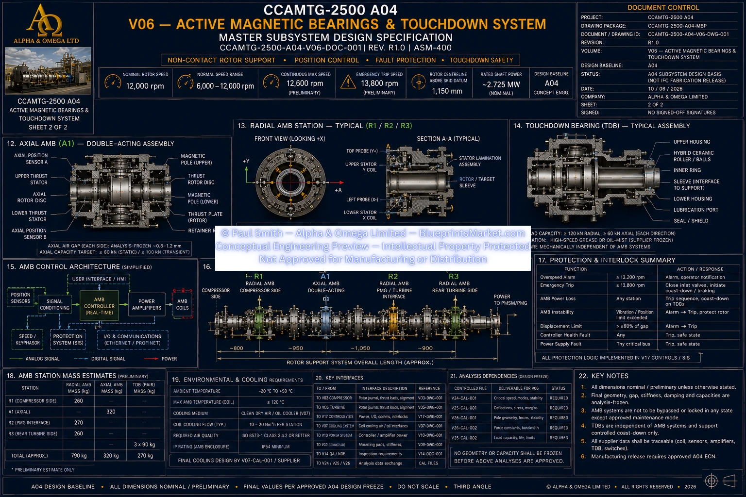
© Paul Smith — Alpha & Omega Limited — PlatformClouds.com — Conceptual Engineering Preview — Not Approved for Manufacturing
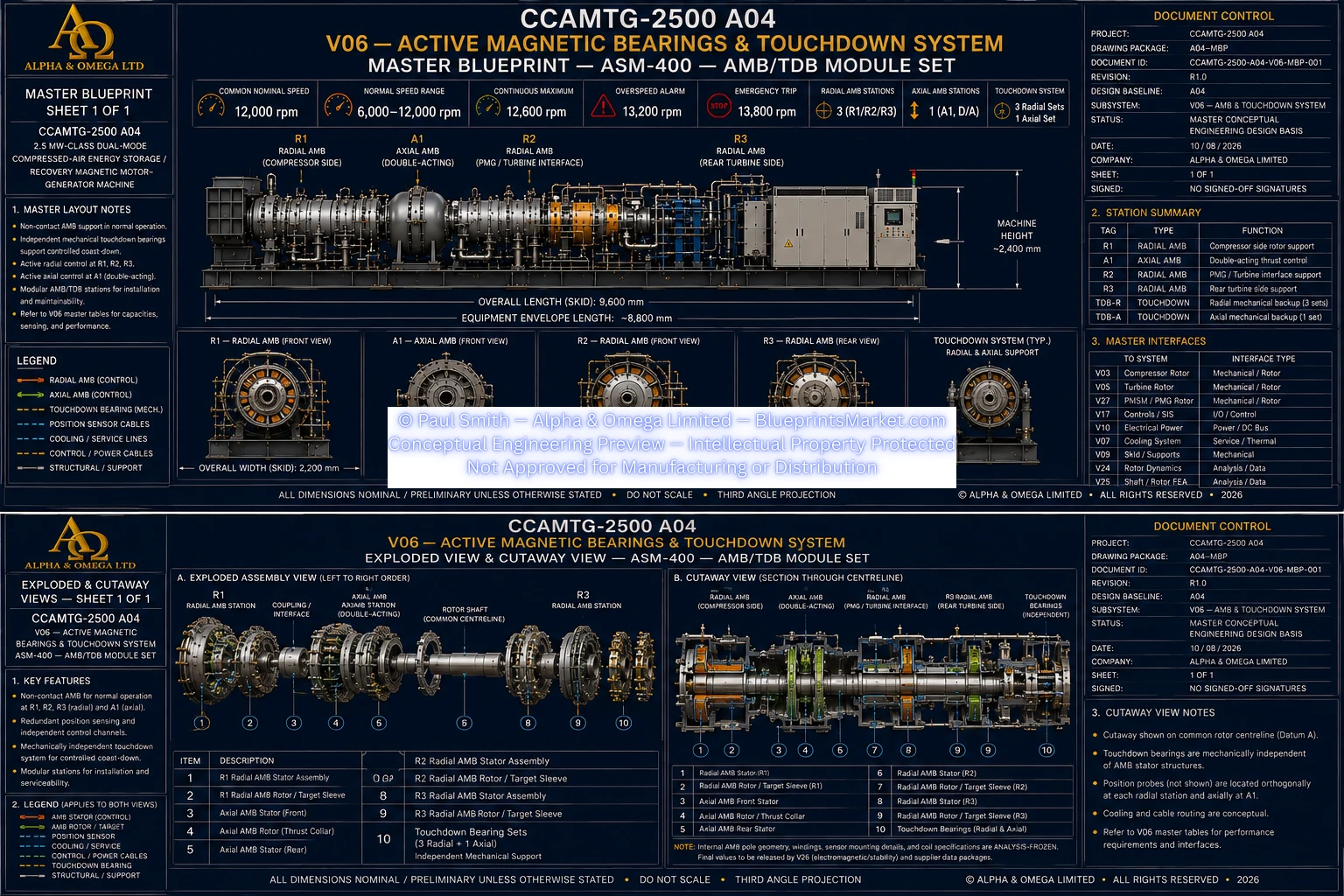
© Paul Smith — Alpha & Omega Limited — PlatformClouds.com — Conceptual Engineering Preview — Not Approved for Manufacturing
V07 — Thermal, Cooling & Airflow Systems
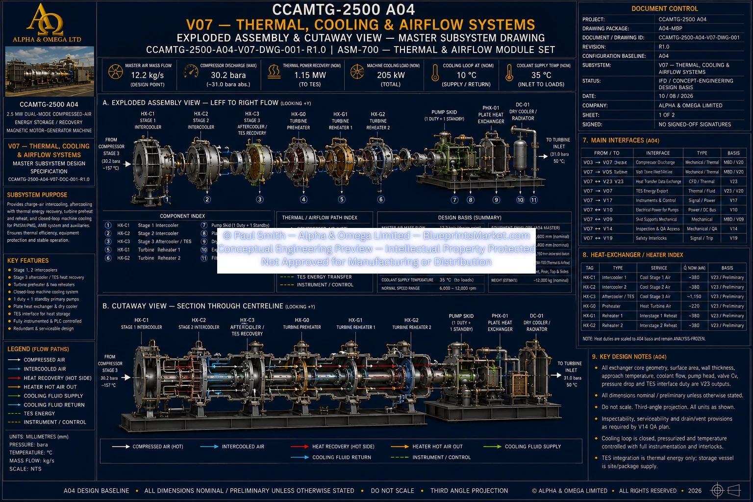
© Paul Smith — Alpha & Omega Limited — PlatformClouds.com — Conceptual Engineering Preview — Not Approved for Manufacturing
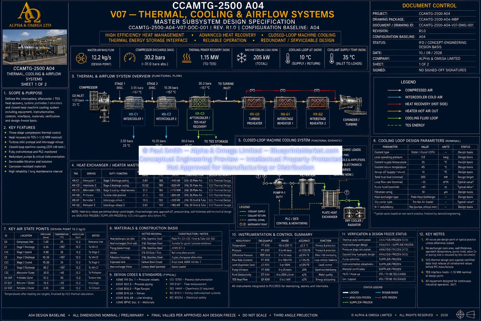
© Paul Smith — Alpha & Omega Limited — PlatformClouds.com — Conceptual Engineering Preview — Not Approved for Manufacturing
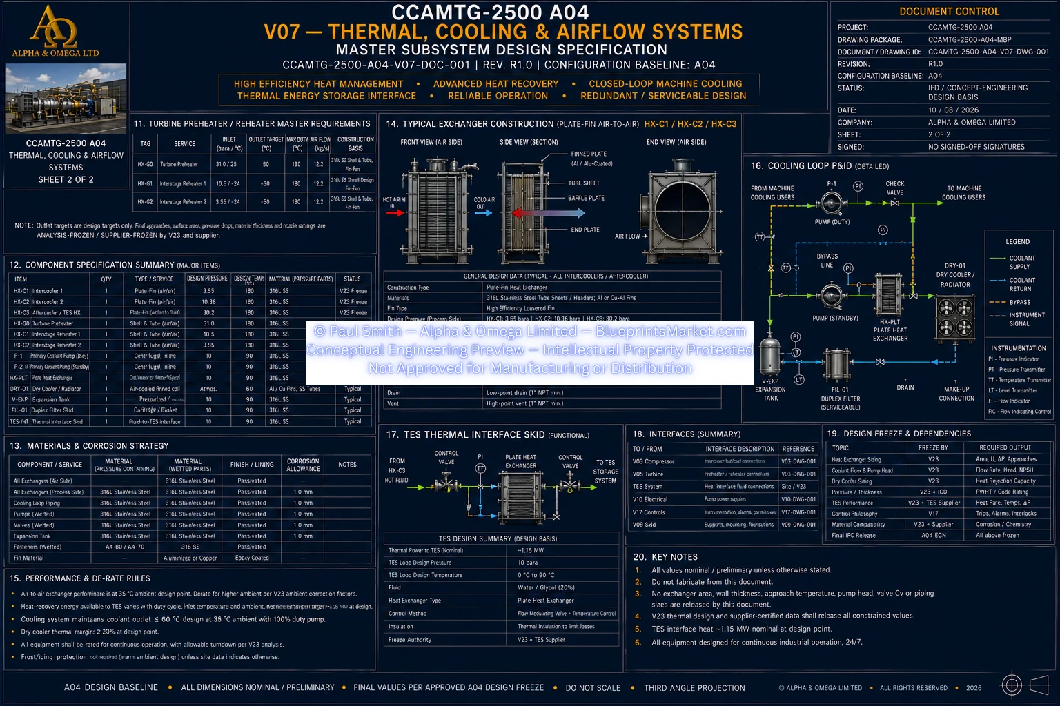
© Paul Smith — Alpha & Omega Limited — PlatformClouds.com — Conceptual Engineering Preview — Not Approved for Manufacturing
V08 — Structural Skid & Foundation Interface
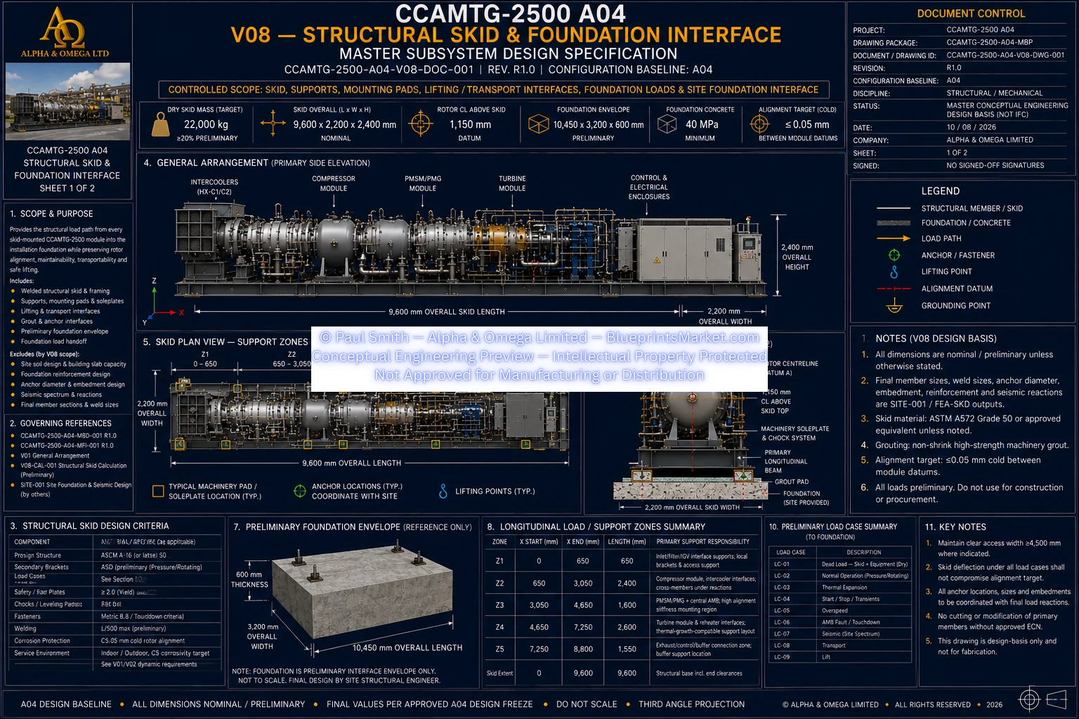
© Paul Smith — Alpha & Omega Limited — PlatformClouds.com — Conceptual Engineering Preview — Not Approved for Manufacturing
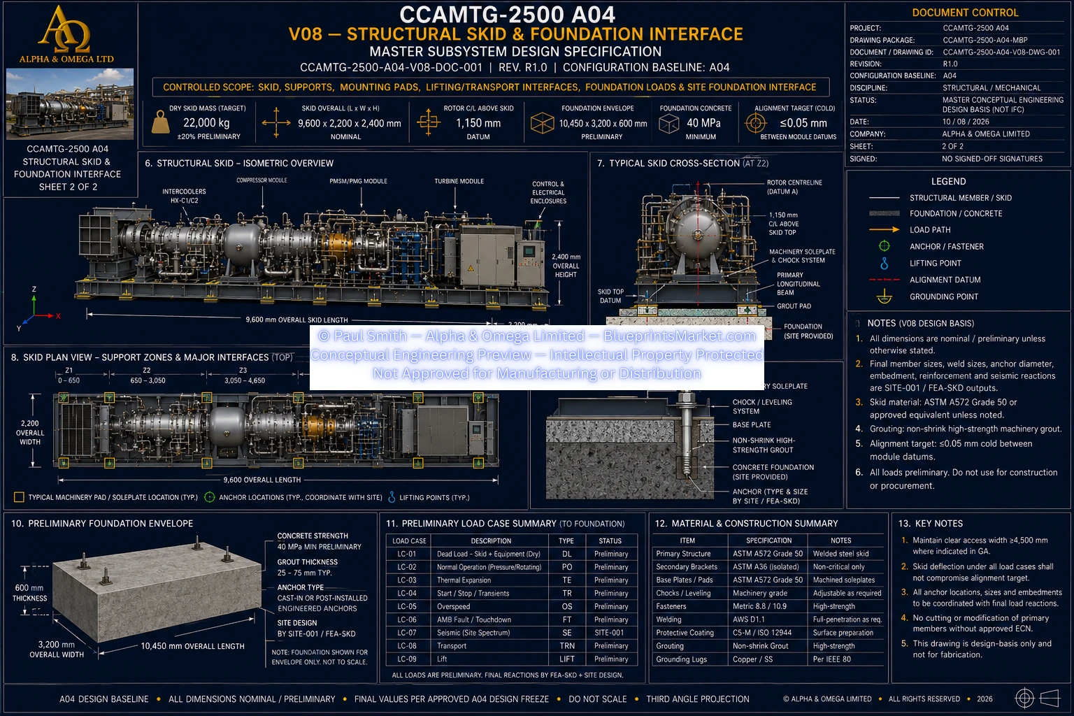
© Paul Smith — Alpha & Omega Limited — PlatformClouds.com — Conceptual Engineering Preview — Not Approved for Manufacturing
V09 — Electrical Power Conversion
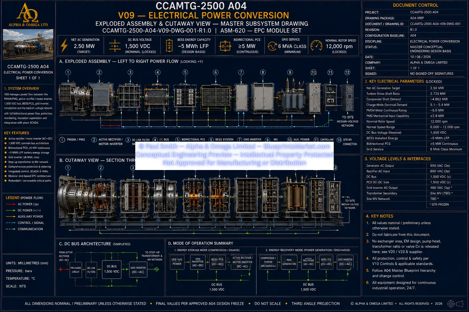
© Paul Smith — Alpha & Omega Limited — PlatformClouds.com — Conceptual Engineering Preview — Not Approved for Manufacturing
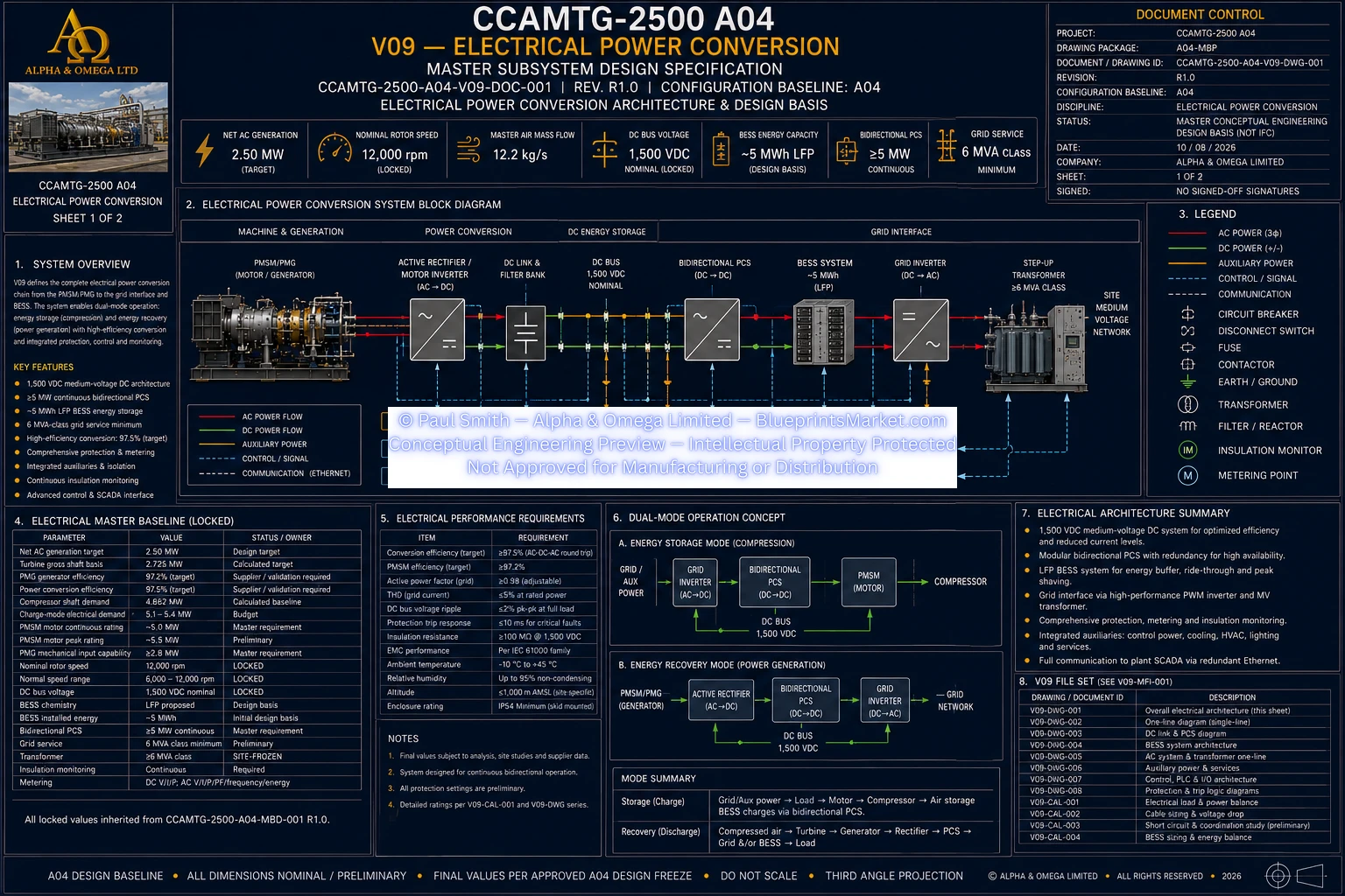
© Paul Smith — Alpha & Omega Limited — PlatformClouds.com — Conceptual Engineering Preview — Not Approved for Manufacturing
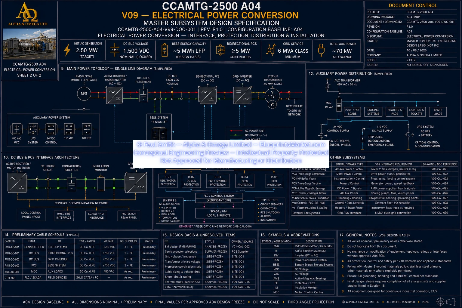
© Paul Smith — Alpha & Omega Limited — PlatformClouds.com — Conceptual Engineering Preview — Not Approved for Manufacturing
V10 — Fasteners, Joints, Sealing & Joint Integrity
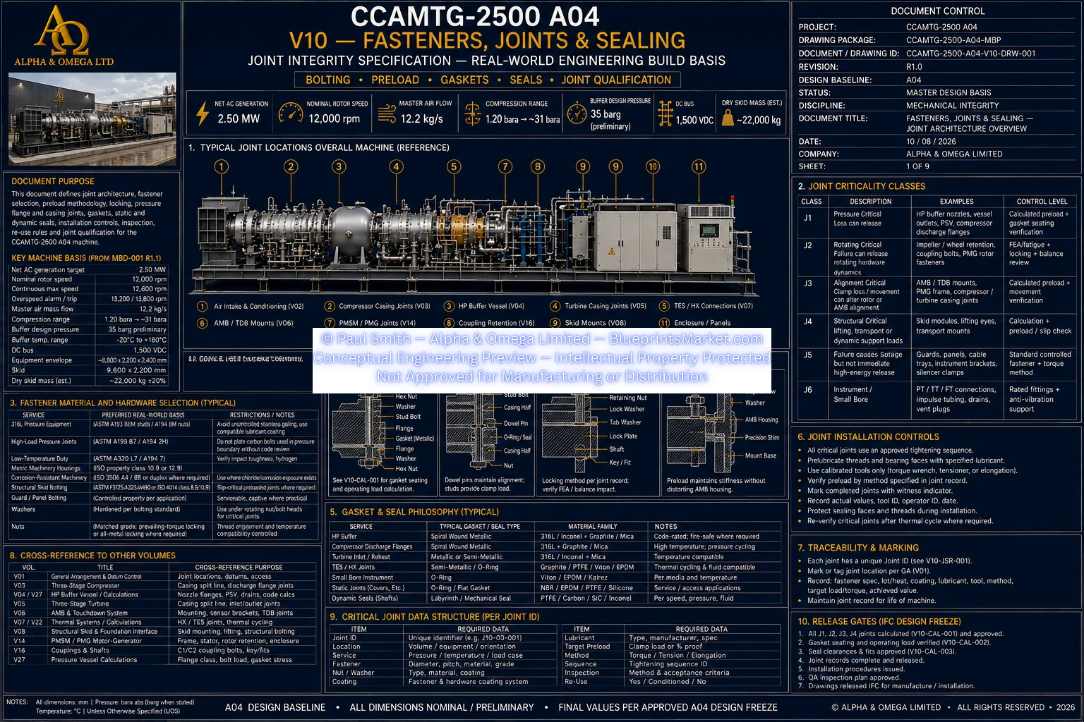
© Paul Smith — Alpha & Omega Limited — PlatformClouds.com — Conceptual Engineering Preview — Not Approved for Manufacturing
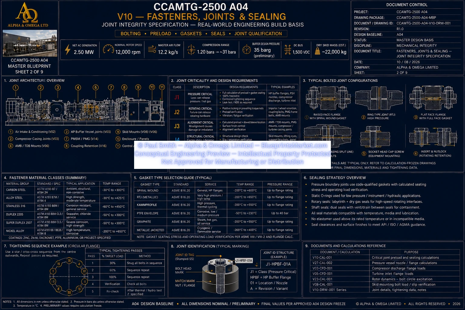
© Paul Smith — Alpha & Omega Limited — PlatformClouds.com — Conceptual Engineering Preview — Not Approved for Manufacturing
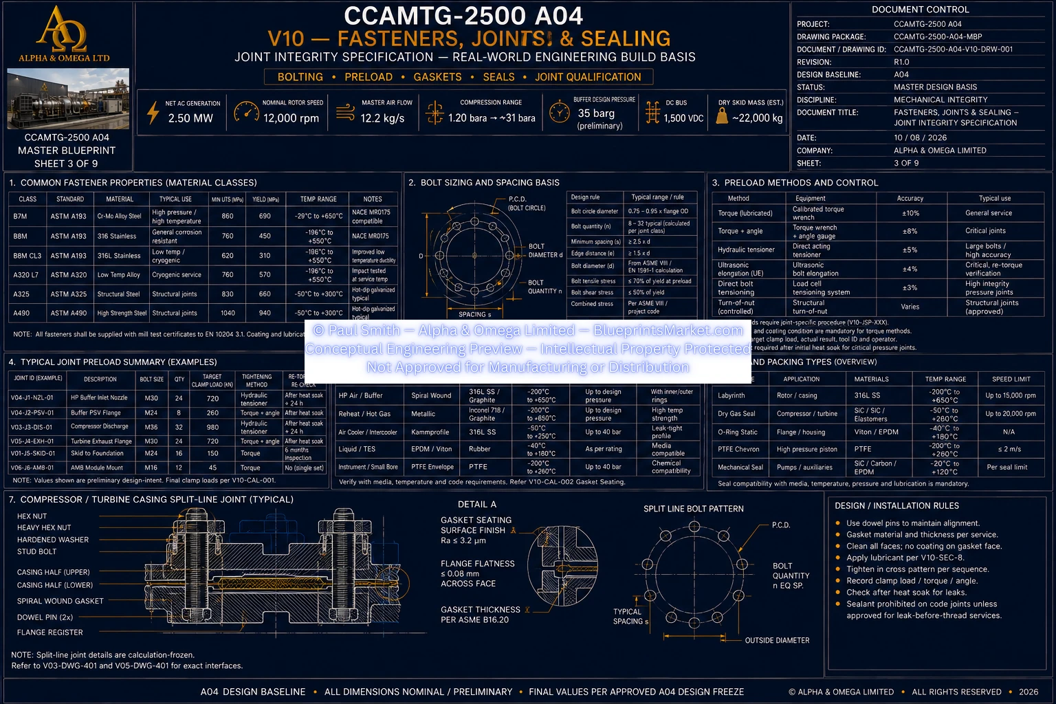
© Paul Smith — Alpha & Omega Limited — PlatformClouds.com — Conceptual Engineering Preview — Not Approved for Manufacturing
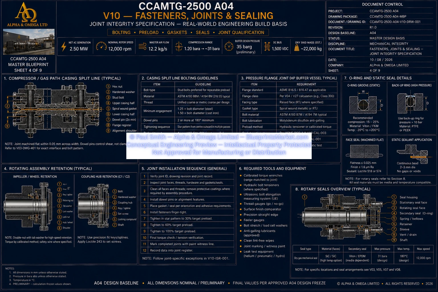
© Paul Smith — Alpha & Omega Limited — PlatformClouds.com — Conceptual Engineering Preview — Not Approved for Manufacturing
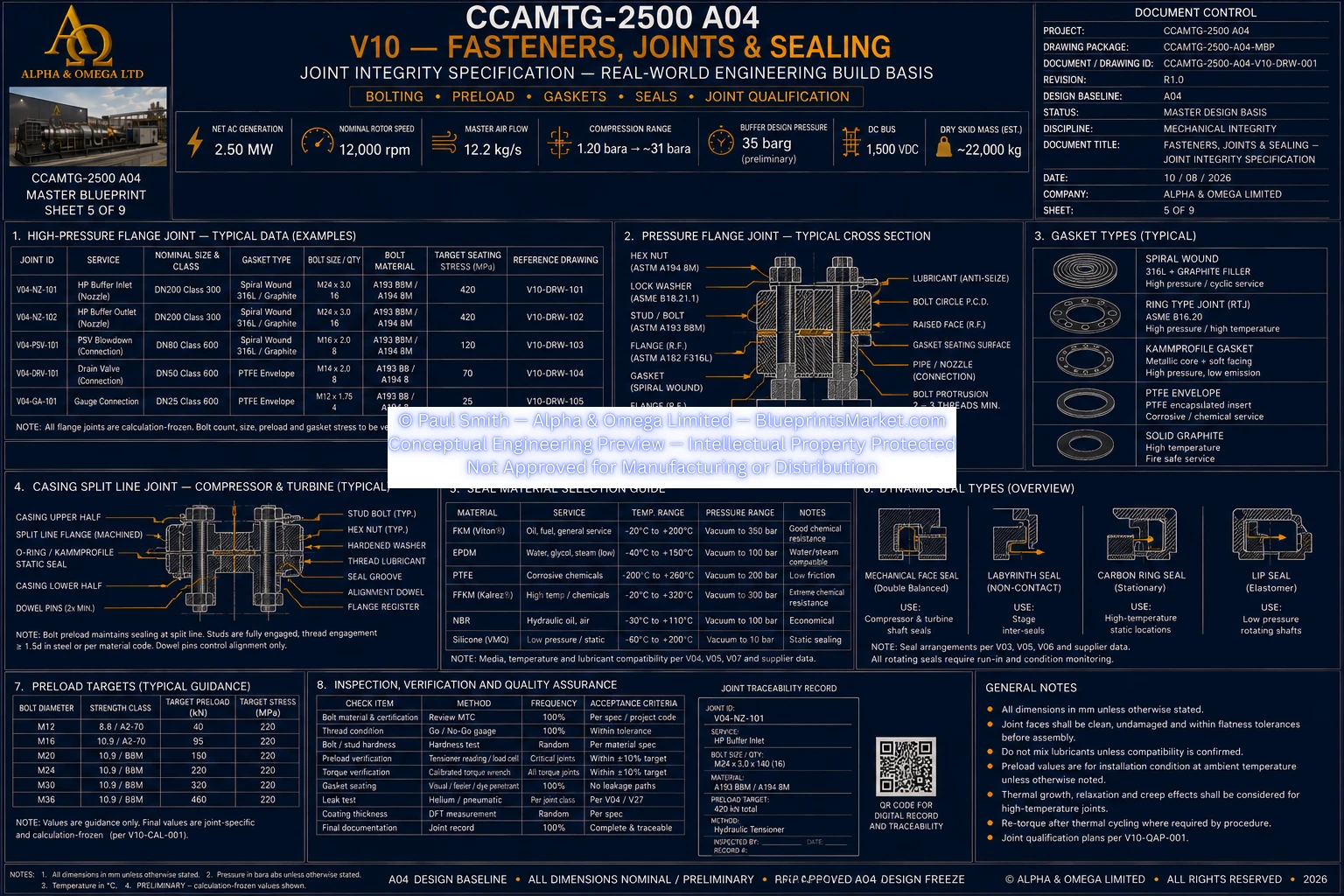
© Paul Smith — Alpha & Omega Limited — PlatformClouds.com — Conceptual Engineering Preview — Not Approved for Manufacturing
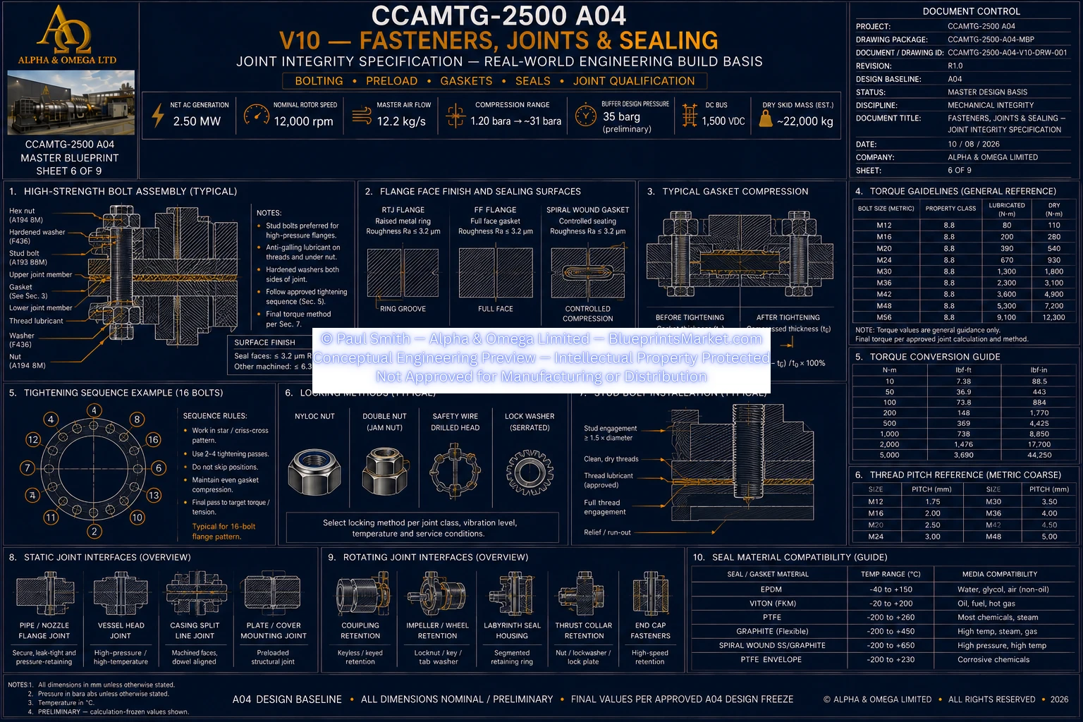
© Paul Smith — Alpha & Omega Limited — PlatformClouds.com — Conceptual Engineering Preview — Not Approved for Manufacturing
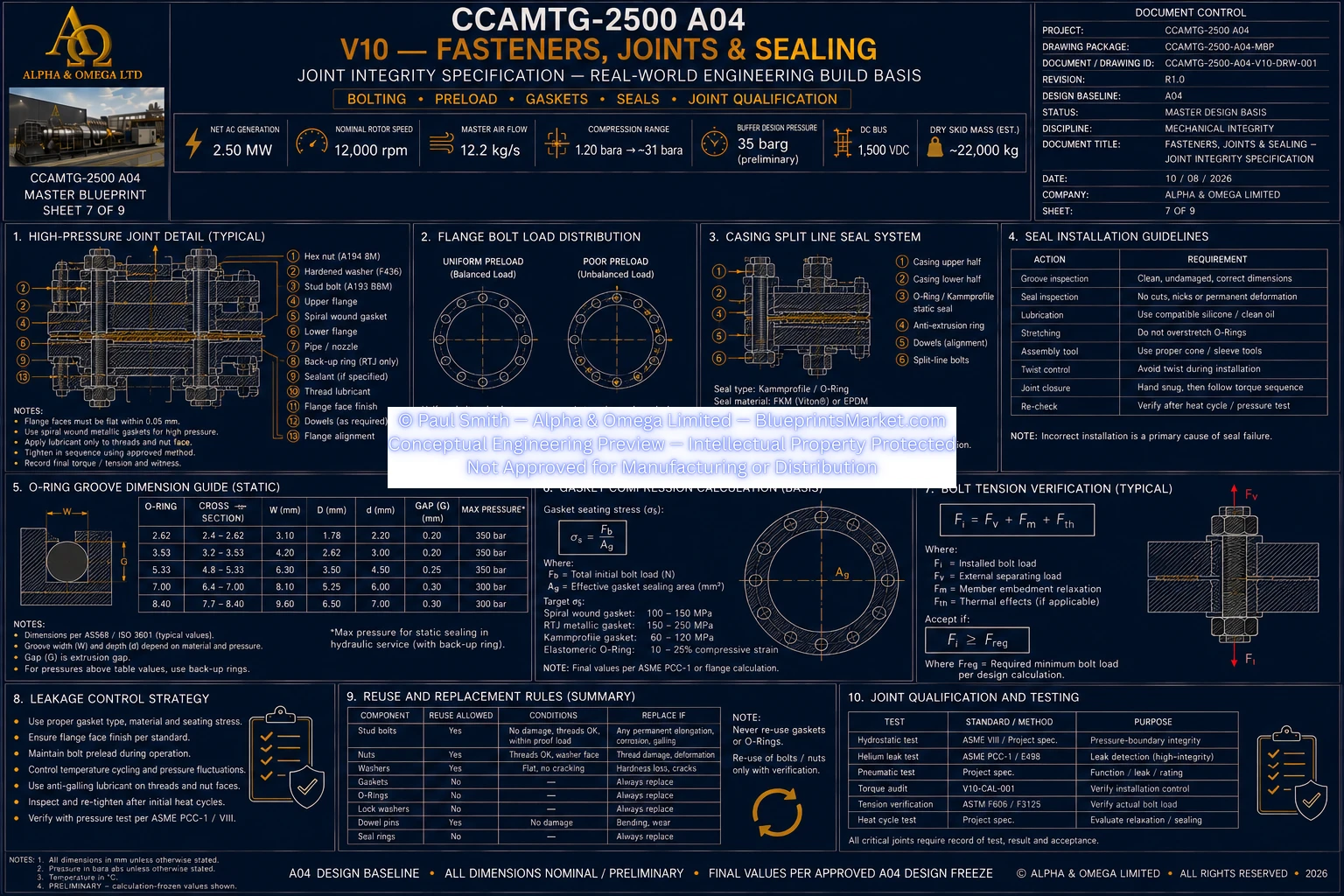
© Paul Smith — Alpha & Omega Limited — PlatformClouds.com — Conceptual Engineering Preview — Not Approved for Manufacturing
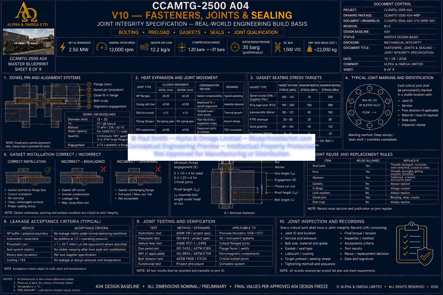
© Paul Smith — Alpha & Omega Limited — PlatformClouds.com — Conceptual Engineering Preview — Not Approved for Manufacturing
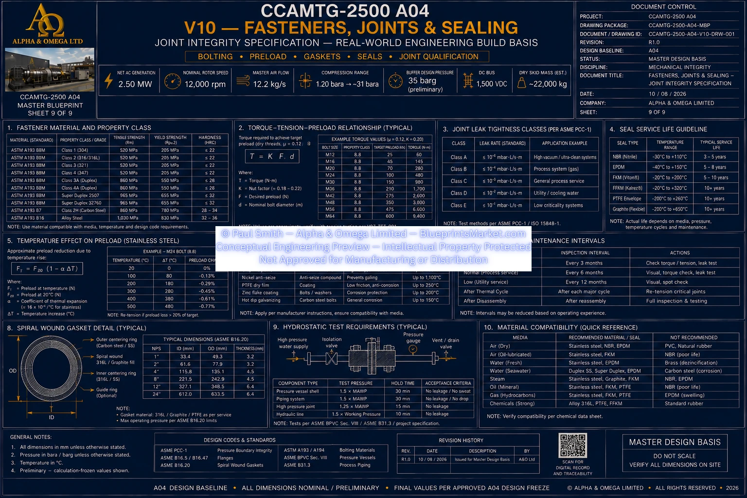
© Paul Smith — Alpha & Omega Limited — PlatformClouds.com — Conceptual Engineering Preview — Not Approved for Manufacturing
V11 / V11A — Full Machine Exploded Assembly & Parts Identification
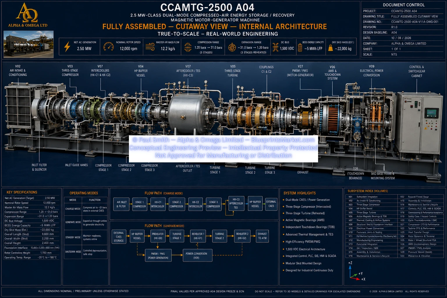
© Paul Smith — Alpha & Omega Limited — PlatformClouds.com — Conceptual Engineering Preview — Not Approved for Manufacturing
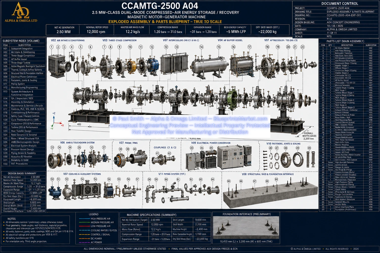
© Paul Smith — Alpha & Omega Limited — PlatformClouds.com — Conceptual Engineering Preview — Not Approved for Manufacturing
V12 — Manufacturing Engineering
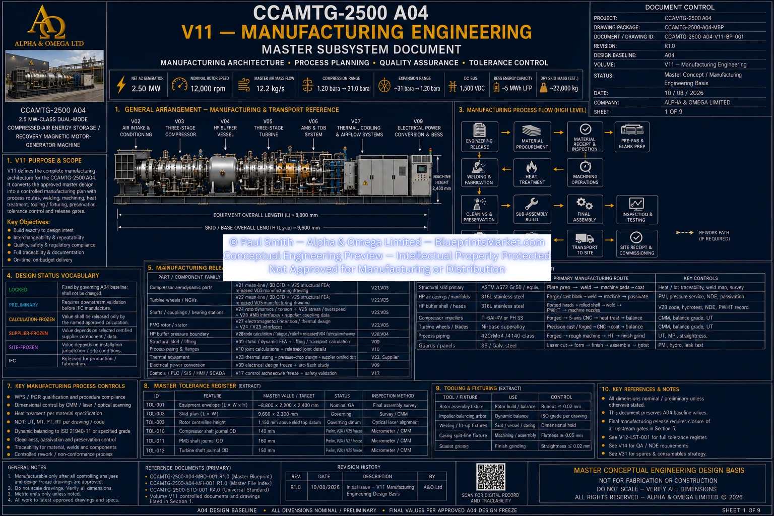
© Paul Smith — Alpha & Omega Limited — PlatformClouds.com — Conceptual Engineering Preview — Not Approved for Manufacturing
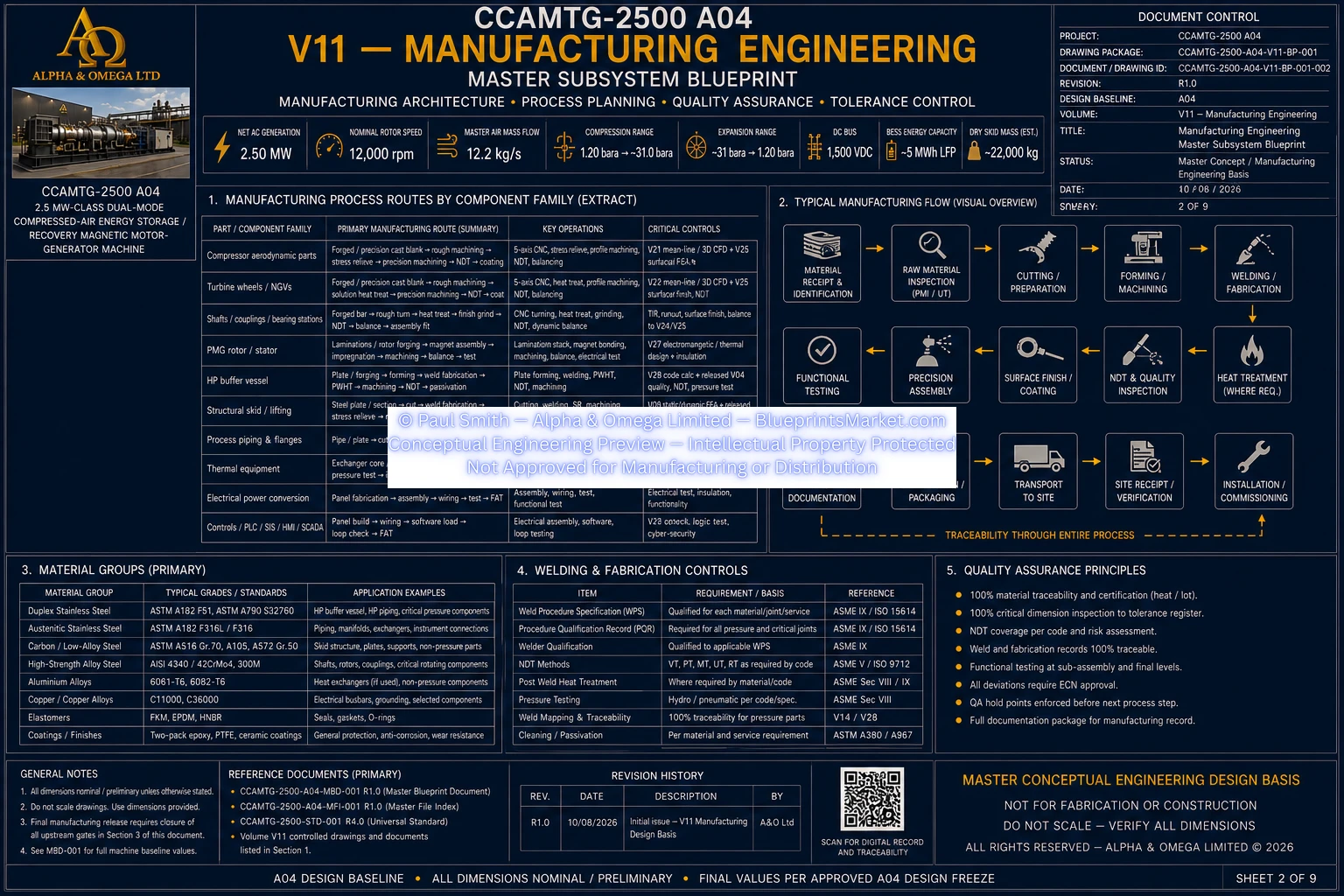
© Paul Smith — Alpha & Omega Limited — PlatformClouds.com — Conceptual Engineering Preview — Not Approved for Manufacturing
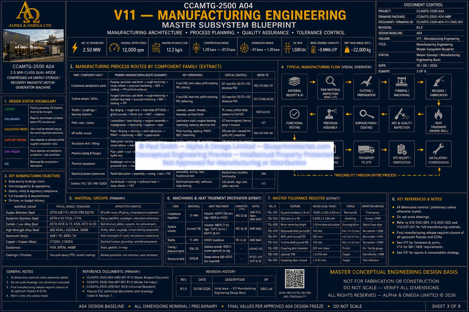
© Paul Smith — Alpha & Omega Limited — PlatformClouds.com — Conceptual Engineering Preview — Not Approved for Manufacturing
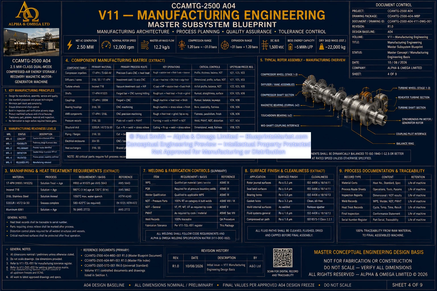
© Paul Smith — Alpha & Omega Limited — PlatformClouds.com — Conceptual Engineering Preview — Not Approved for Manufacturing
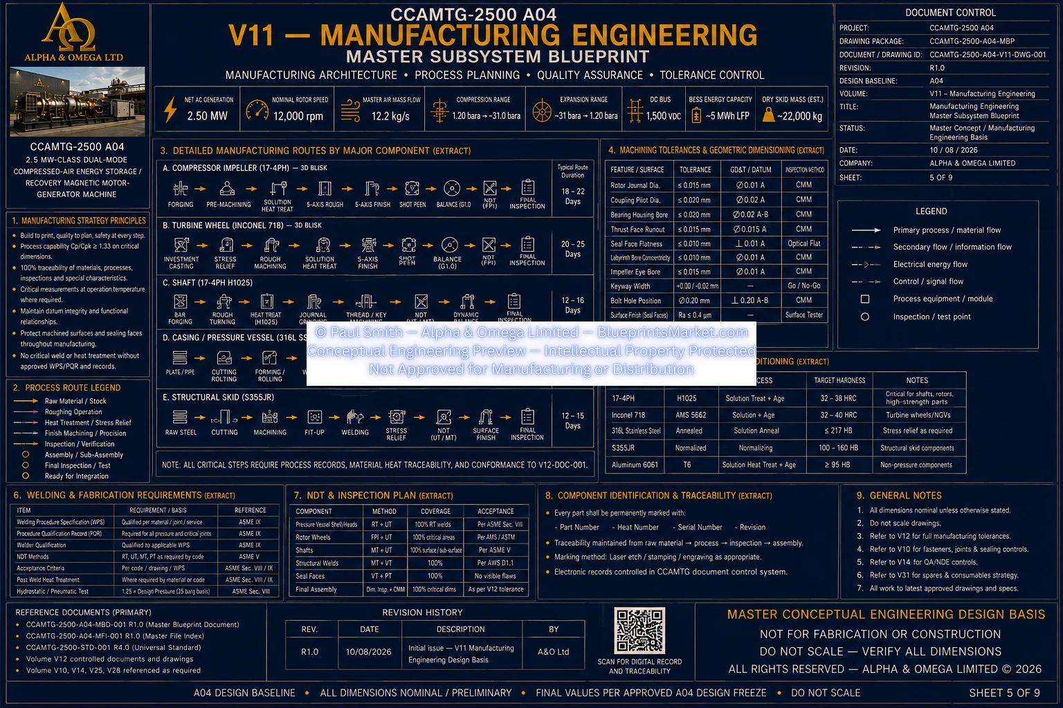
© Paul Smith — Alpha & Omega Limited — PlatformClouds.com — Conceptual Engineering Preview — Not Approved for Manufacturing
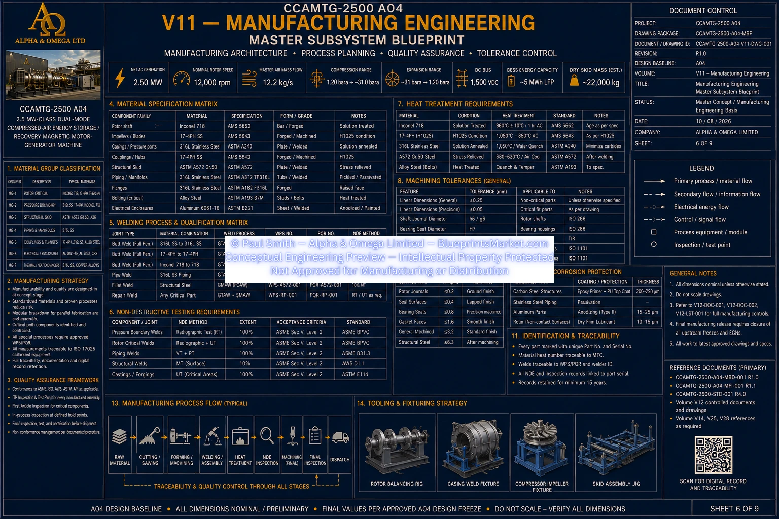
© Paul Smith — Alpha & Omega Limited — PlatformClouds.com — Conceptual Engineering Preview — Not Approved for Manufacturing
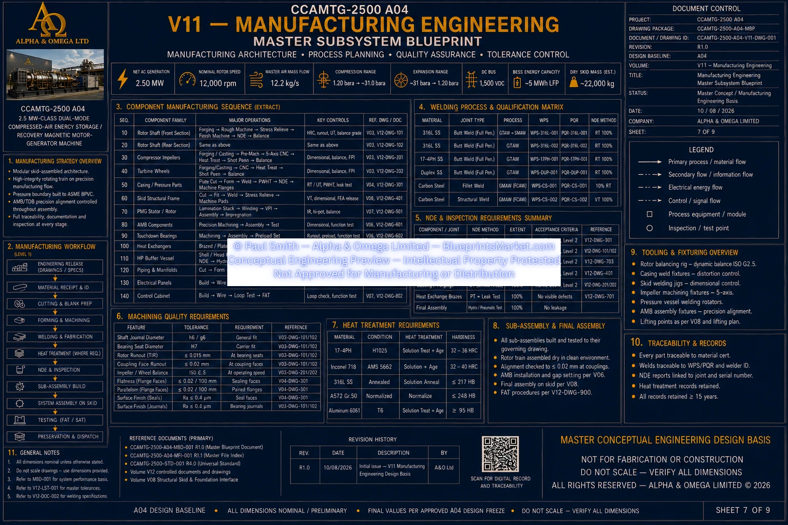
© Paul Smith — Alpha & Omega Limited — PlatformClouds.com — Conceptual Engineering Preview — Not Approved for Manufacturing
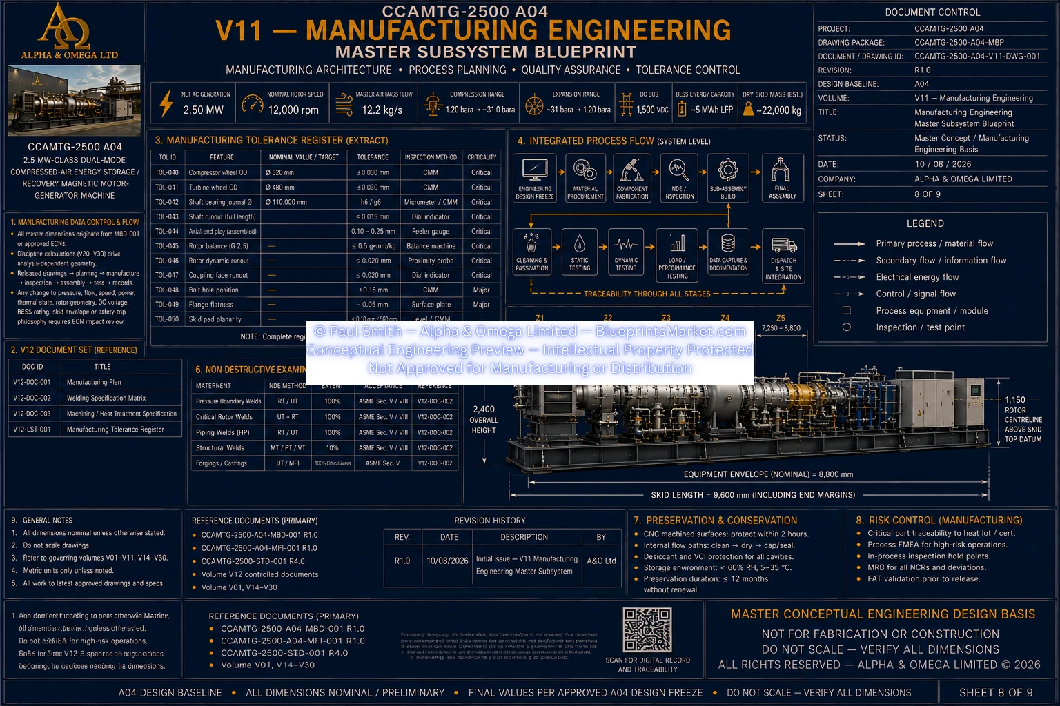
© Paul Smith — Alpha & Omega Limited — PlatformClouds.com — Conceptual Engineering Preview — Not Approved for Manufacturing
V13 — System Architecture & Functional Integration
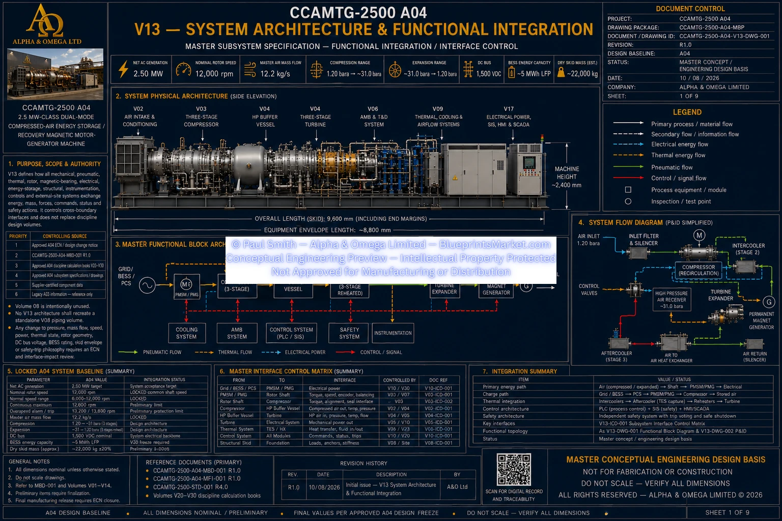
© Paul Smith — Alpha & Omega Limited — PlatformClouds.com — Conceptual Engineering Preview — Not Approved for Manufacturing

© Paul Smith — Alpha & Omega Limited — PlatformClouds.com — Conceptual Engineering Preview — Not Approved for Manufacturing
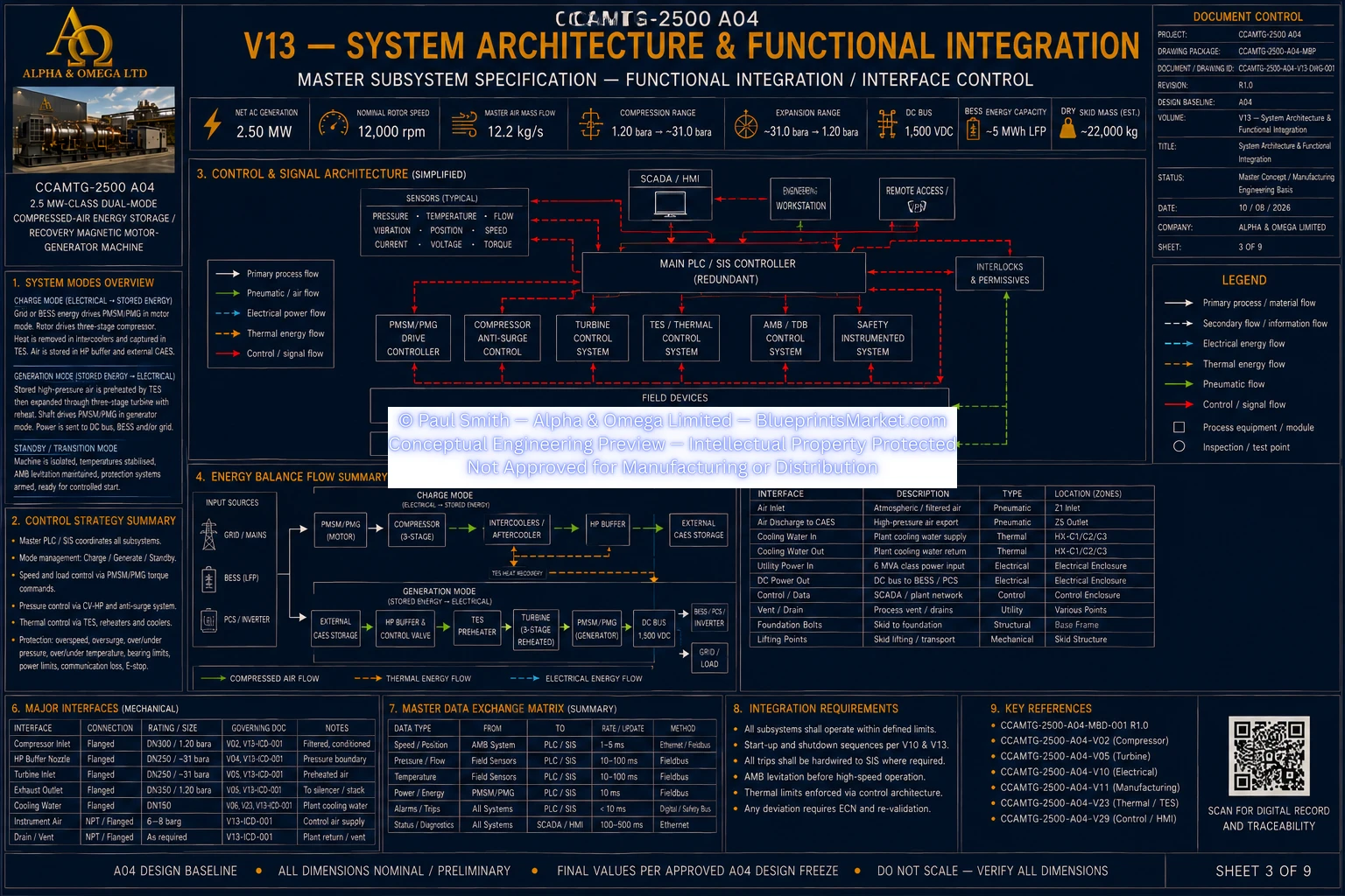
© Paul Smith — Alpha & Omega Limited — PlatformClouds.com — Conceptual Engineering Preview — Not Approved for Manufacturing
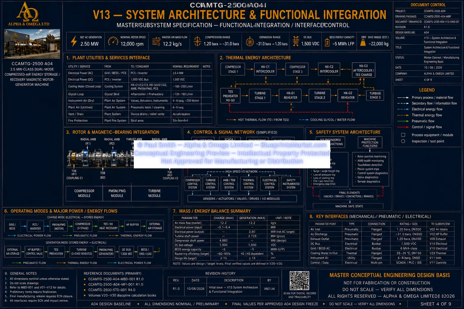
© Paul Smith — Alpha & Omega Limited — PlatformClouds.com — Conceptual Engineering Preview — Not Approved for Manufacturing
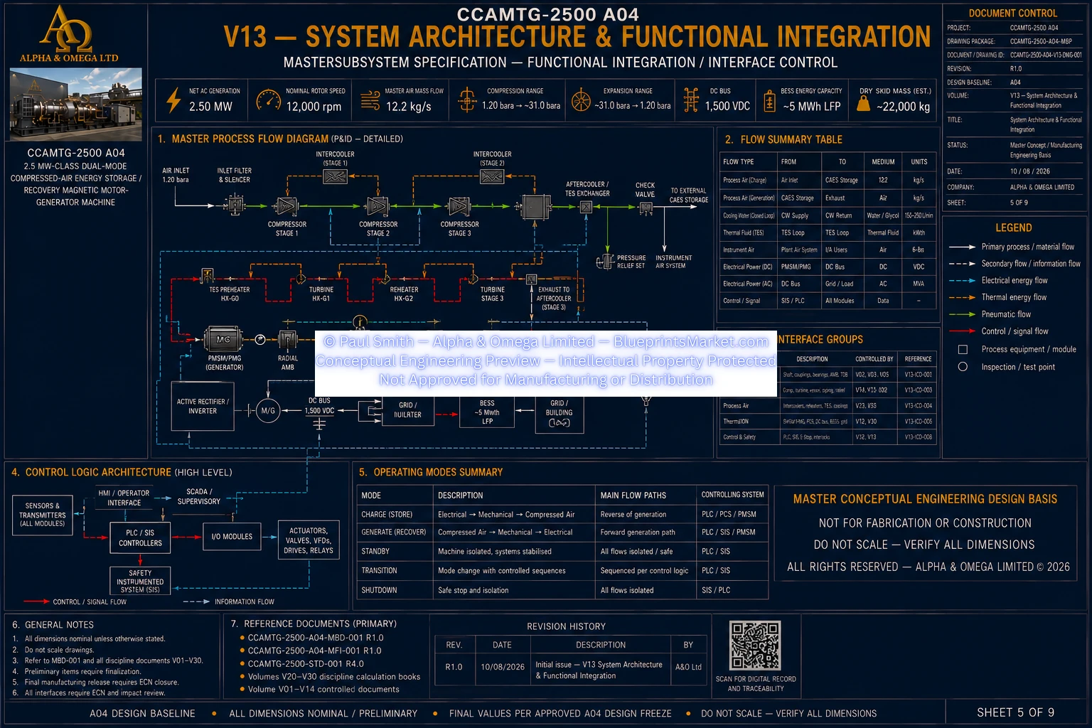
© Paul Smith — Alpha & Omega Limited — PlatformClouds.com — Conceptual Engineering Preview — Not Approved for Manufacturing
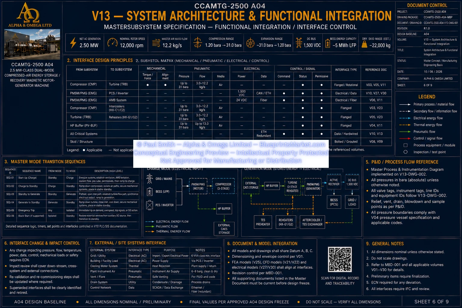
© Paul Smith — Alpha & Omega Limited — PlatformClouds.com — Conceptual Engineering Preview — Not Approved for Manufacturing
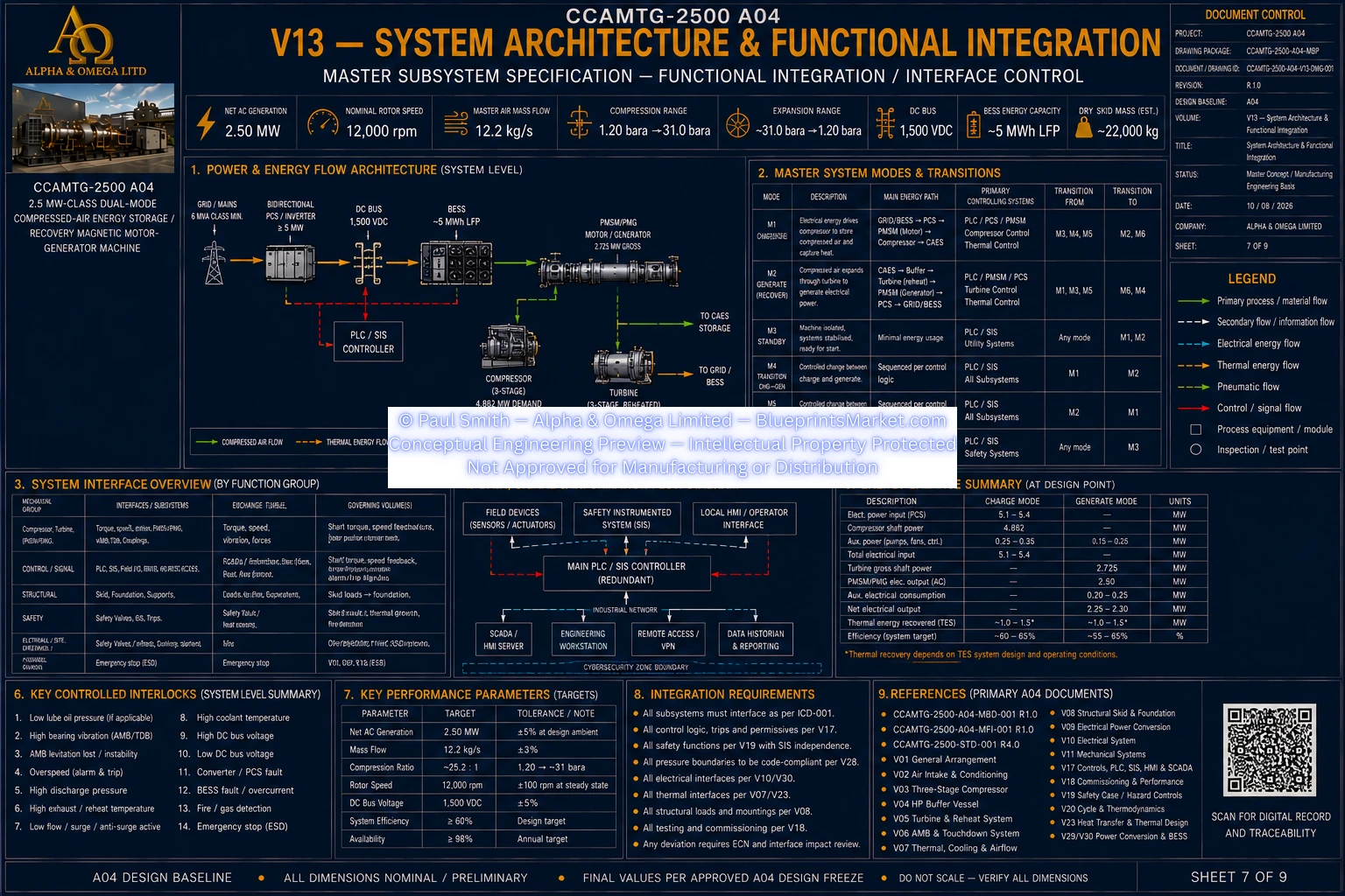
© Paul Smith — Alpha & Omega Limited — PlatformClouds.com — Conceptual Engineering Preview — Not Approved for Manufacturing
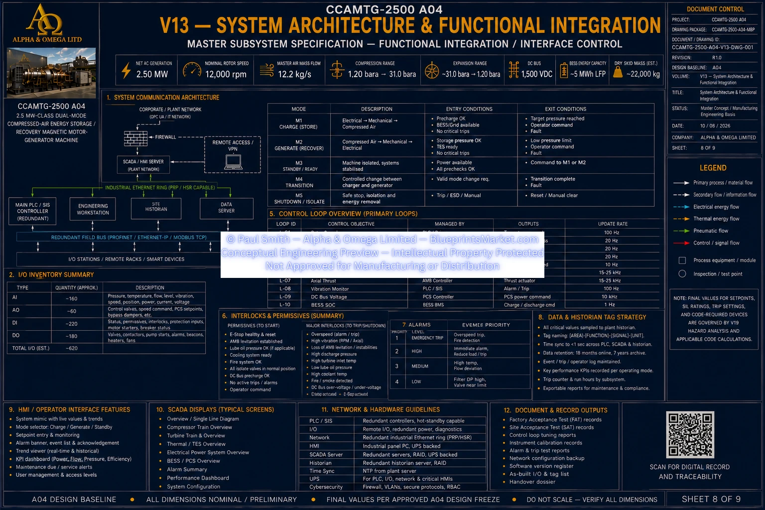
© Paul Smith — Alpha & Omega Limited — PlatformClouds.com — Conceptual Engineering Preview — Not Approved for Manufacturing
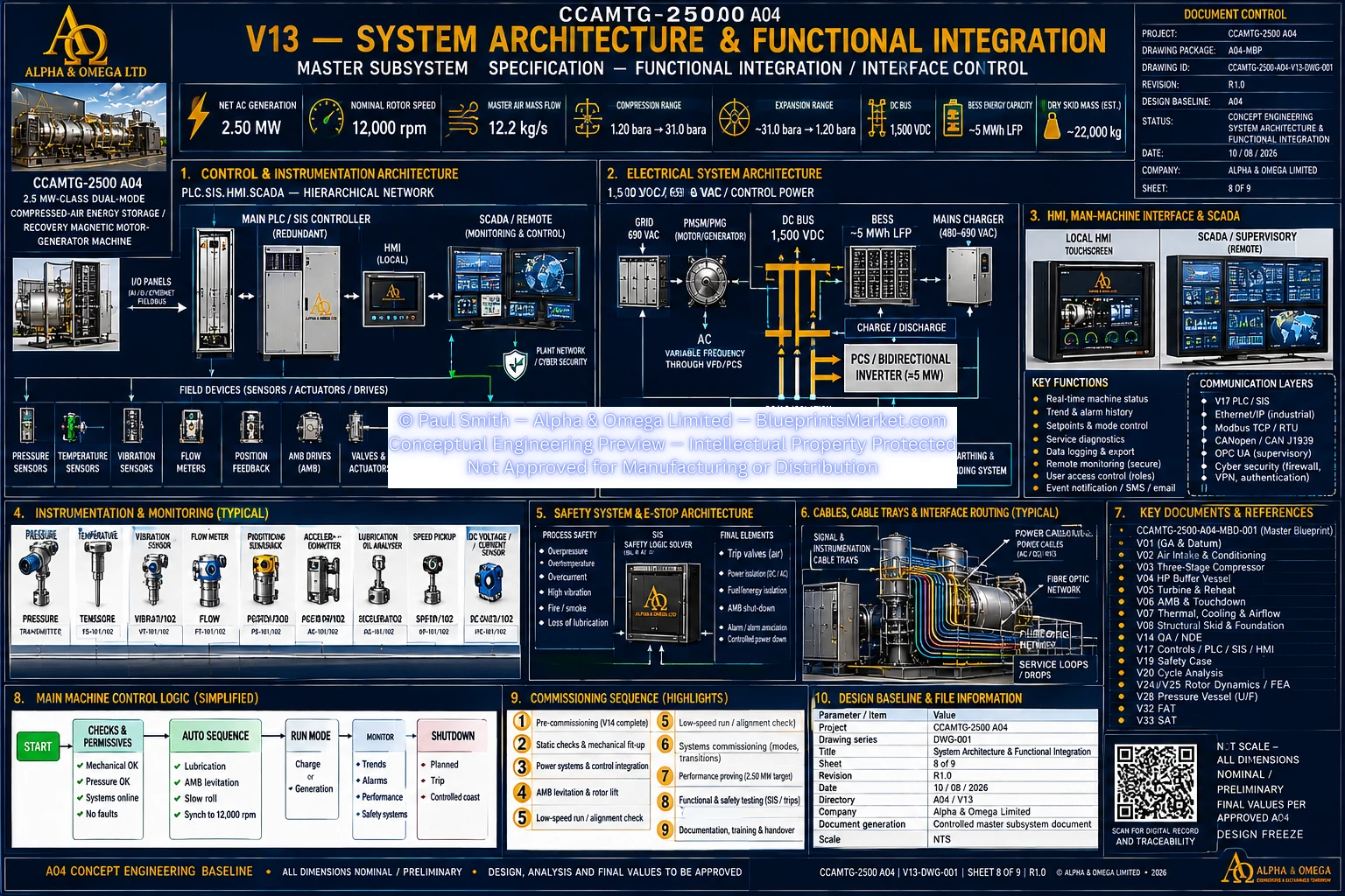
© Paul Smith — Alpha & Omega Limited — PlatformClouds.com — Conceptual Engineering Preview — Not Approved for Manufacturing
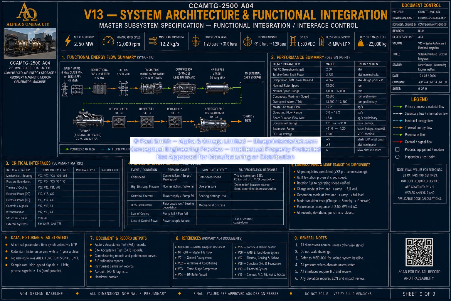
© Paul Smith — Alpha & Omega Limited — PlatformClouds.com — Conceptual Engineering Preview — Not Approved for Manufacturing
V14 — QA / Inspection / NDE
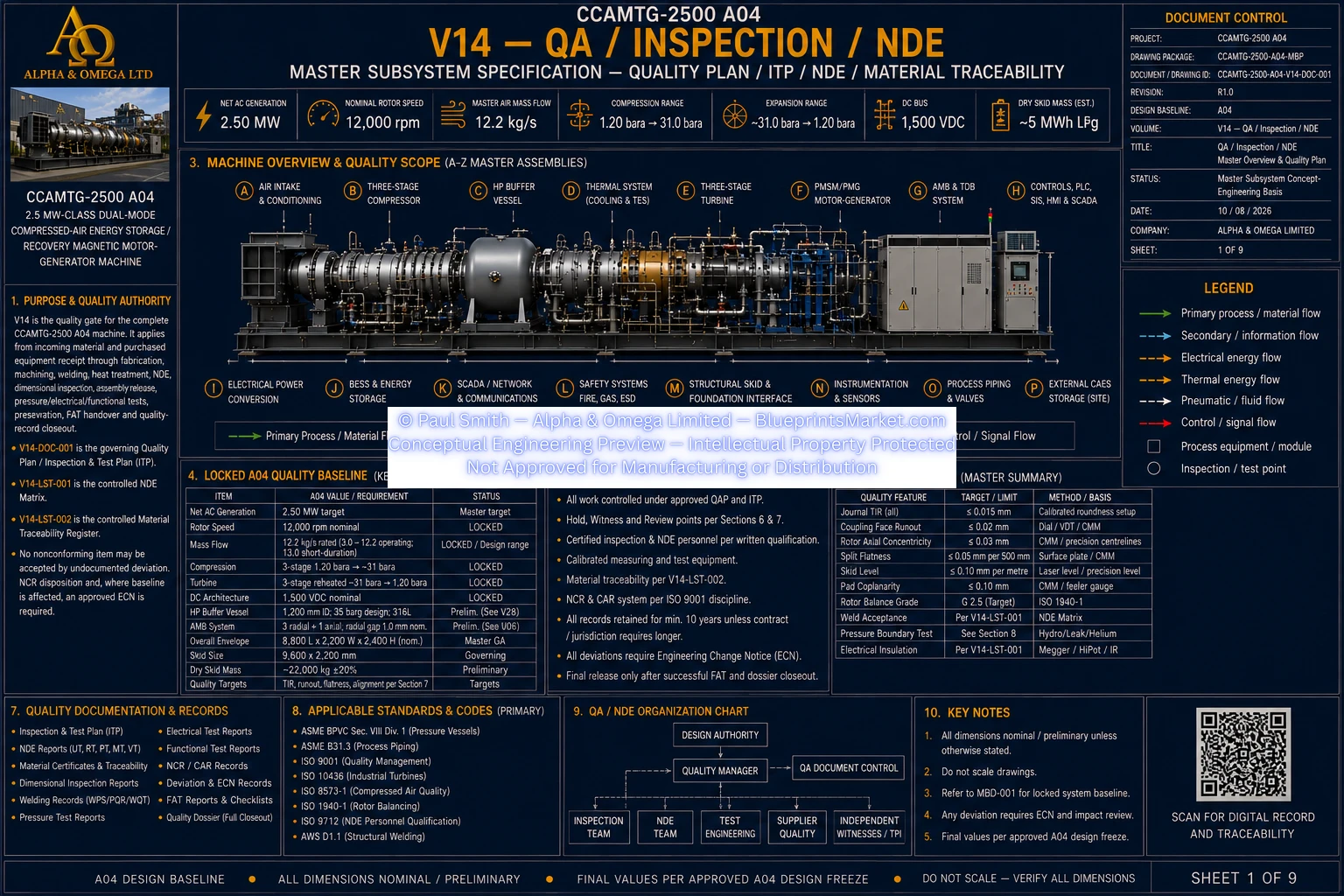
© Paul Smith — Alpha & Omega Limited — PlatformClouds.com — Conceptual Engineering Preview — Not Approved for Manufacturing
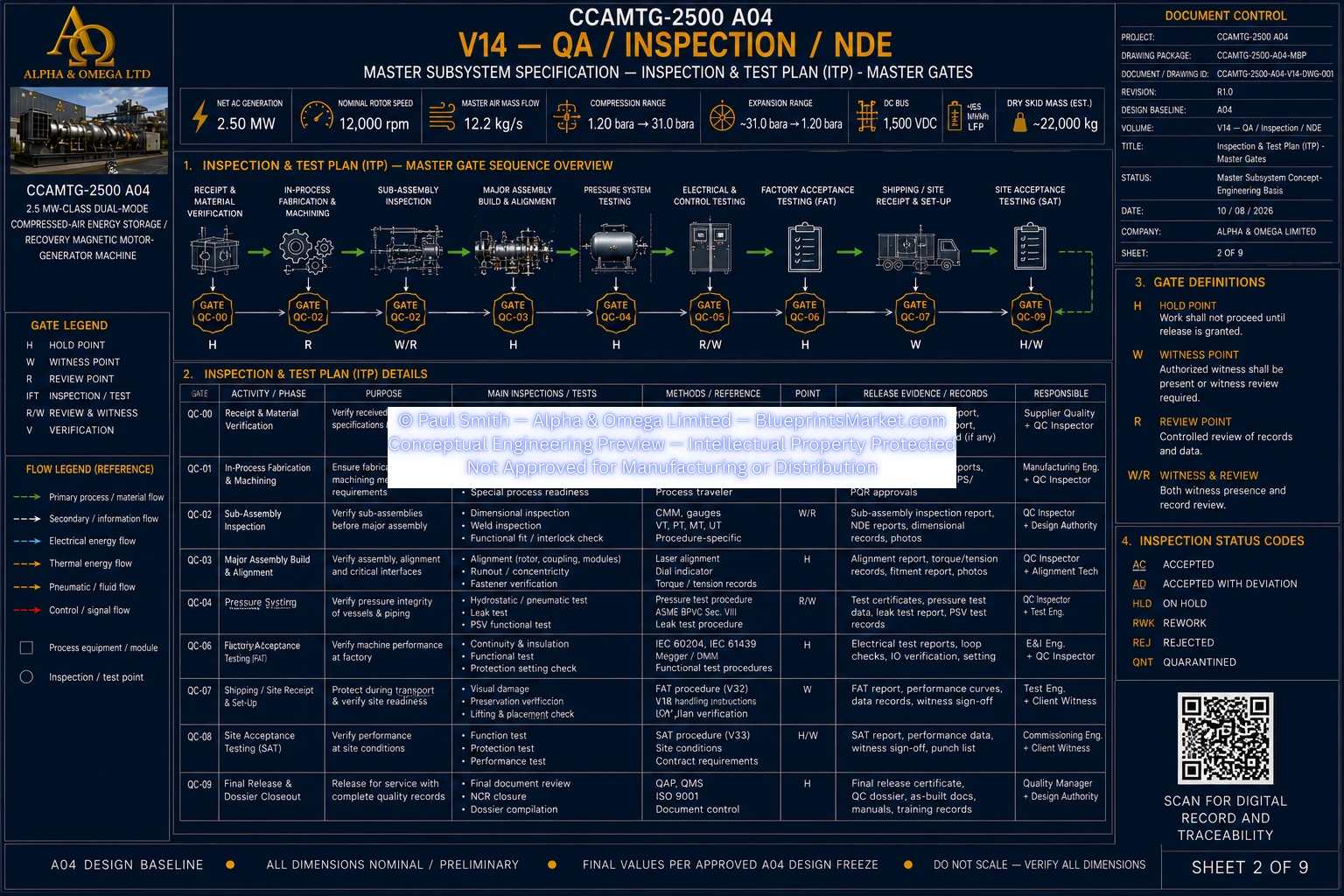
© Paul Smith — Alpha & Omega Limited — PlatformClouds.com — Conceptual Engineering Preview — Not Approved for Manufacturing
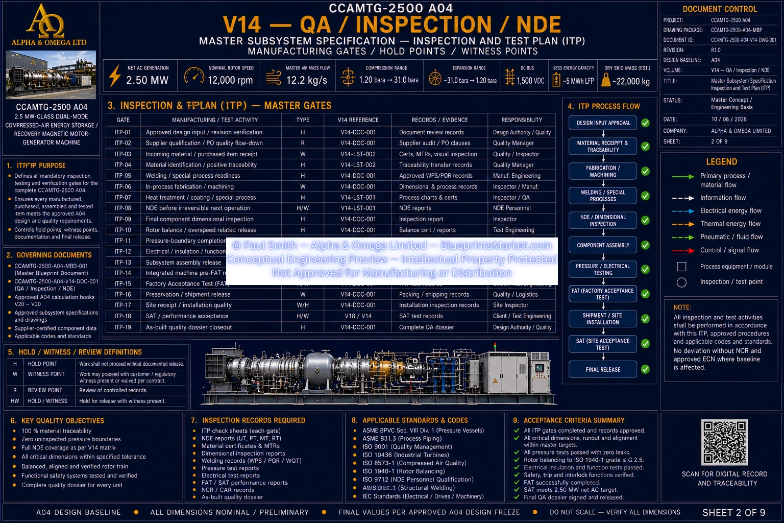
© Paul Smith — Alpha & Omega Limited — PlatformClouds.com — Conceptual Engineering Preview — Not Approved for Manufacturing
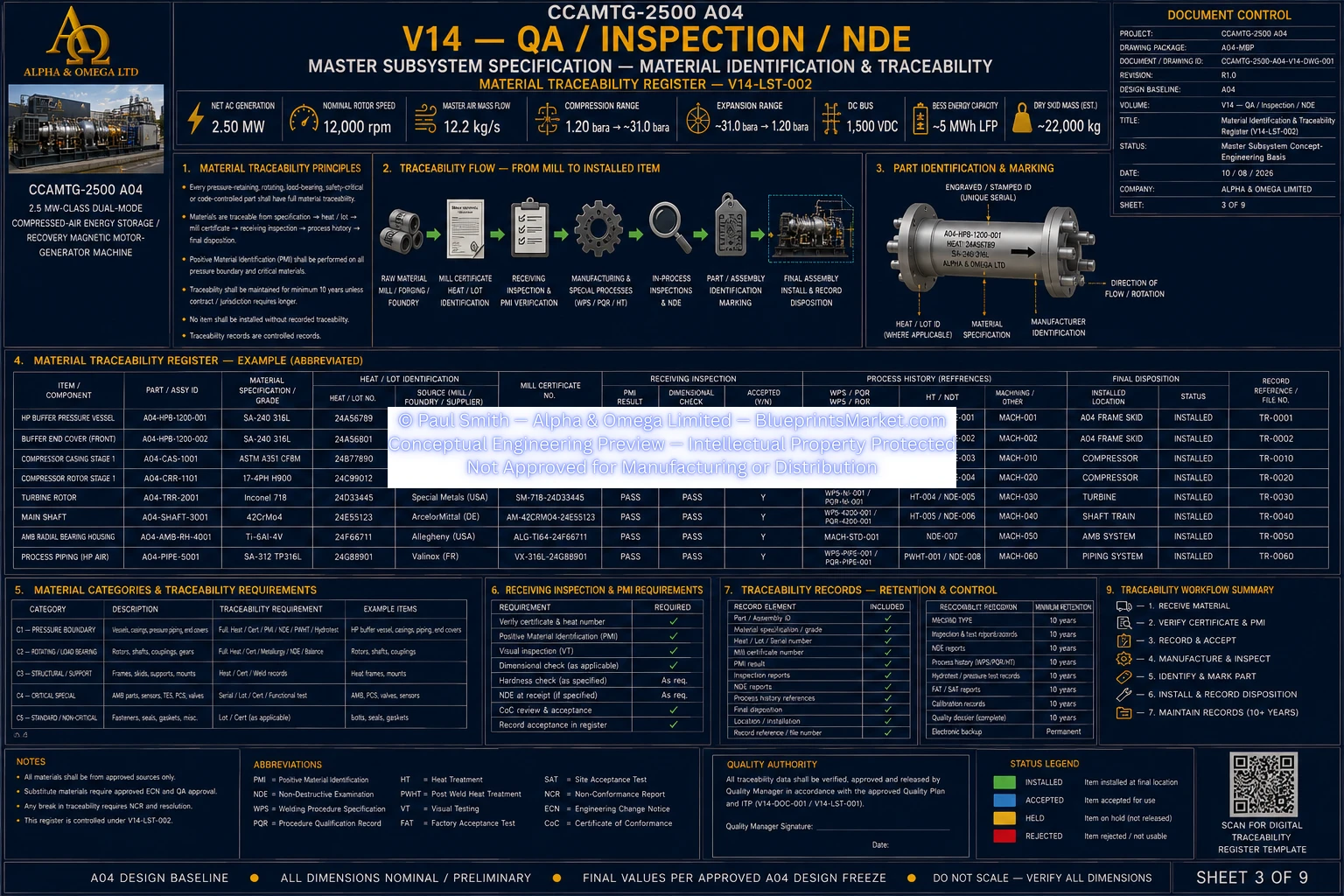
© Paul Smith — Alpha & Omega Limited — PlatformClouds.com — Conceptual Engineering Preview — Not Approved for Manufacturing
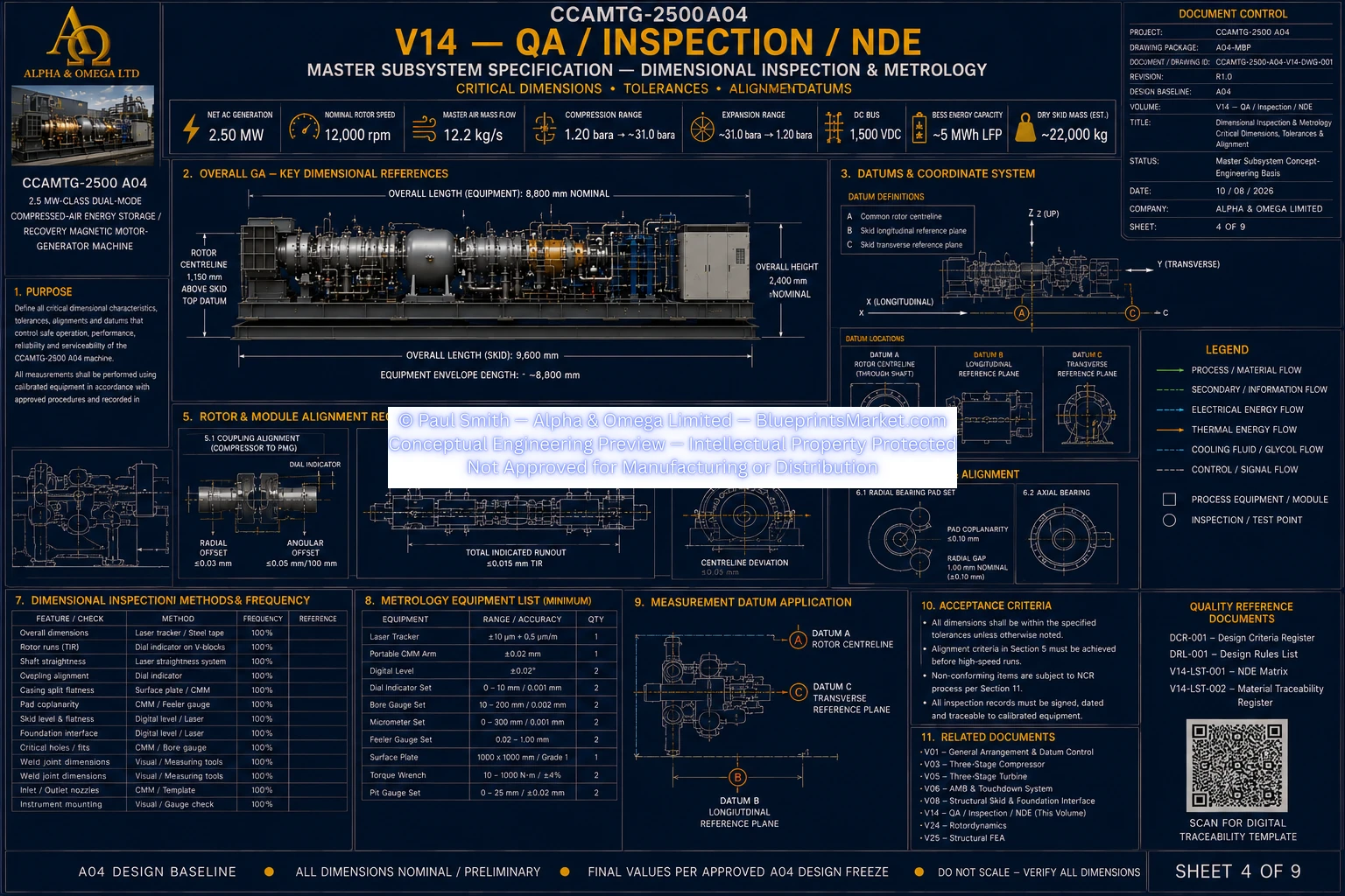
© Paul Smith — Alpha & Omega Limited — PlatformClouds.com — Conceptual Engineering Preview — Not Approved for Manufacturing
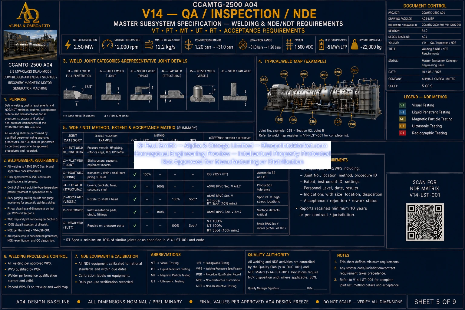
© Paul Smith — Alpha & Omega Limited — PlatformClouds.com — Conceptual Engineering Preview — Not Approved for Manufacturing
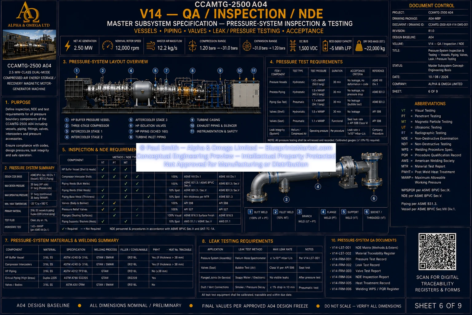
© Paul Smith — Alpha & Omega Limited — PlatformClouds.com — Conceptual Engineering Preview — Not Approved for Manufacturing
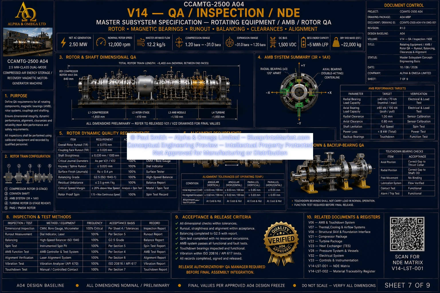
© Paul Smith — Alpha & Omega Limited — PlatformClouds.com — Conceptual Engineering Preview — Not Approved for Manufacturing
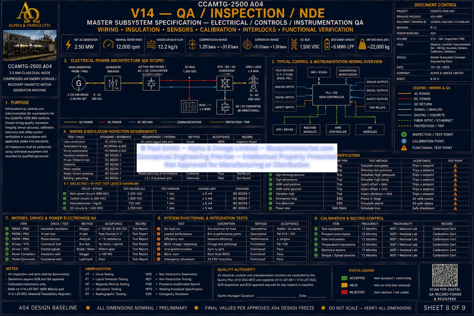
© Paul Smith — Alpha & Omega Limited — PlatformClouds.com — Conceptual Engineering Preview — Not Approved for Manufacturing
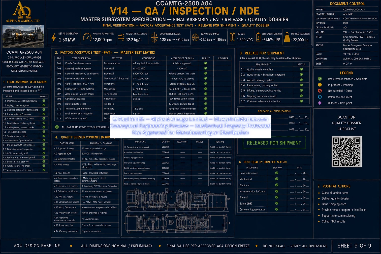
© Paul Smith — Alpha & Omega Limited — PlatformClouds.com — Conceptual Engineering Preview — Not Approved for Manufacturing
V15 — Assembly & Installation
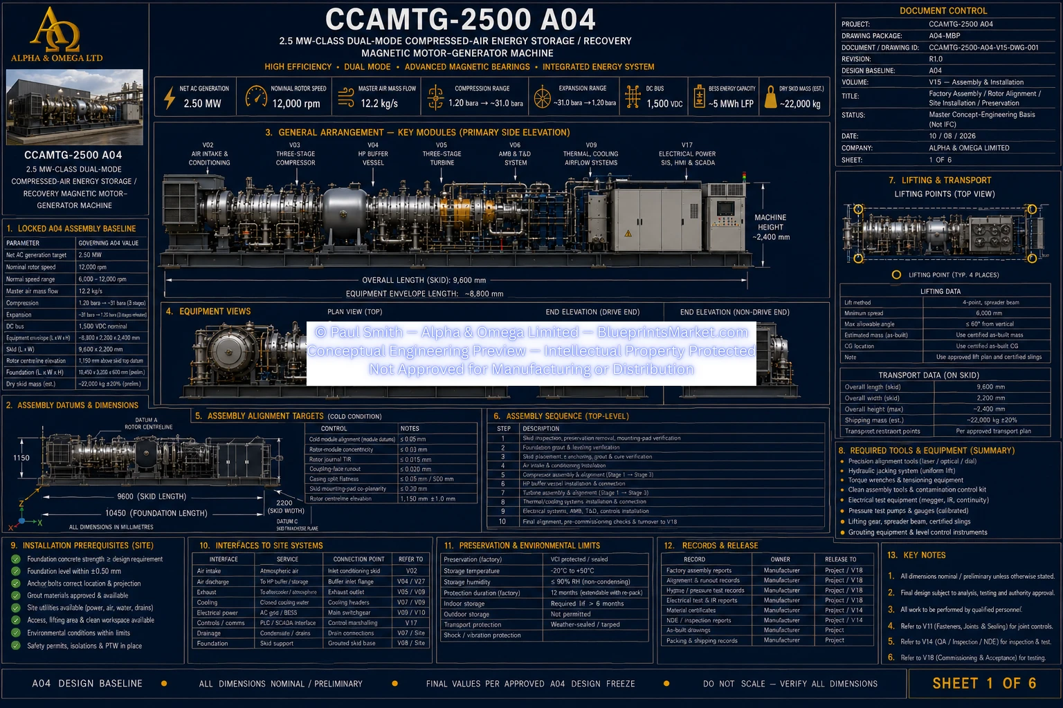
© Paul Smith — Alpha & Omega Limited — PlatformClouds.com — Conceptual Engineering Preview — Not Approved for Manufacturing
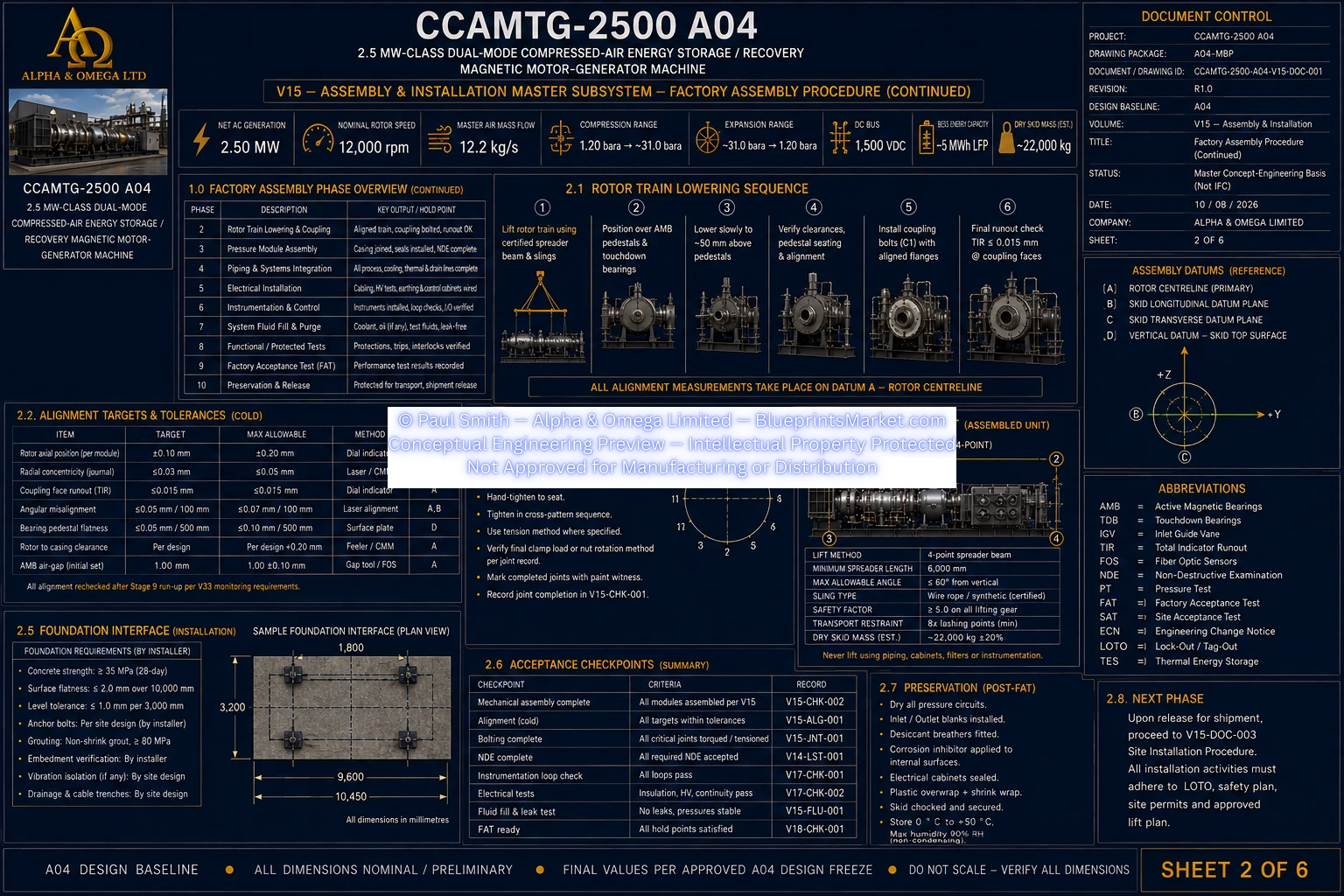
© Paul Smith — Alpha & Omega Limited — PlatformClouds.com — Conceptual Engineering Preview — Not Approved for Manufacturing
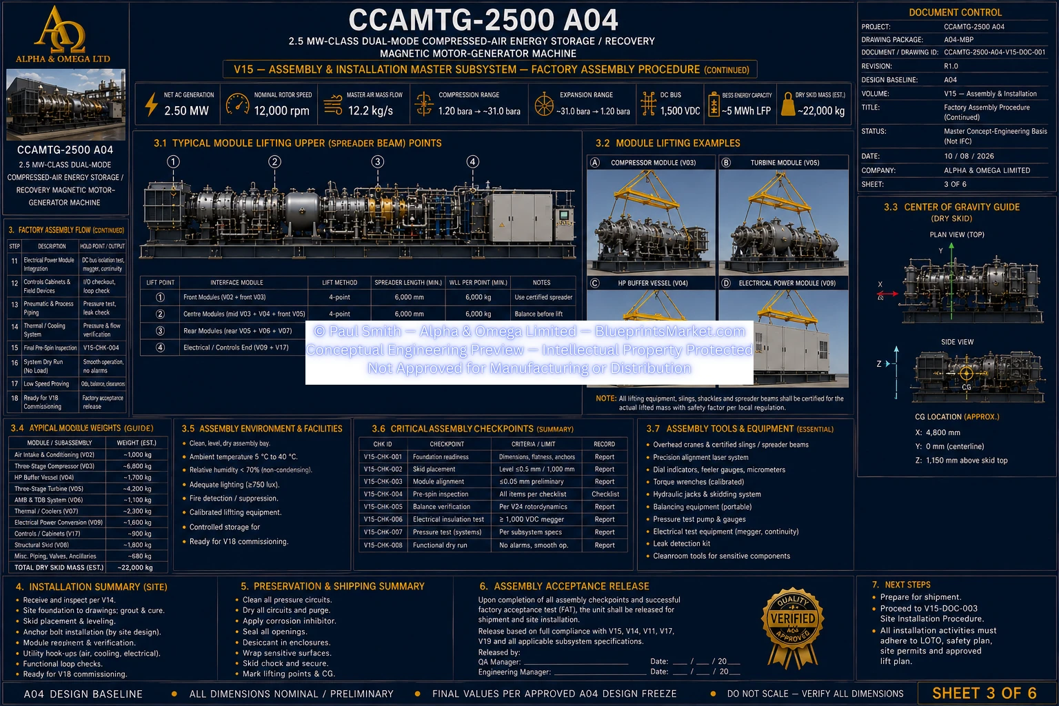
© Paul Smith — Alpha & Omega Limited — PlatformClouds.com — Conceptual Engineering Preview — Not Approved for Manufacturing
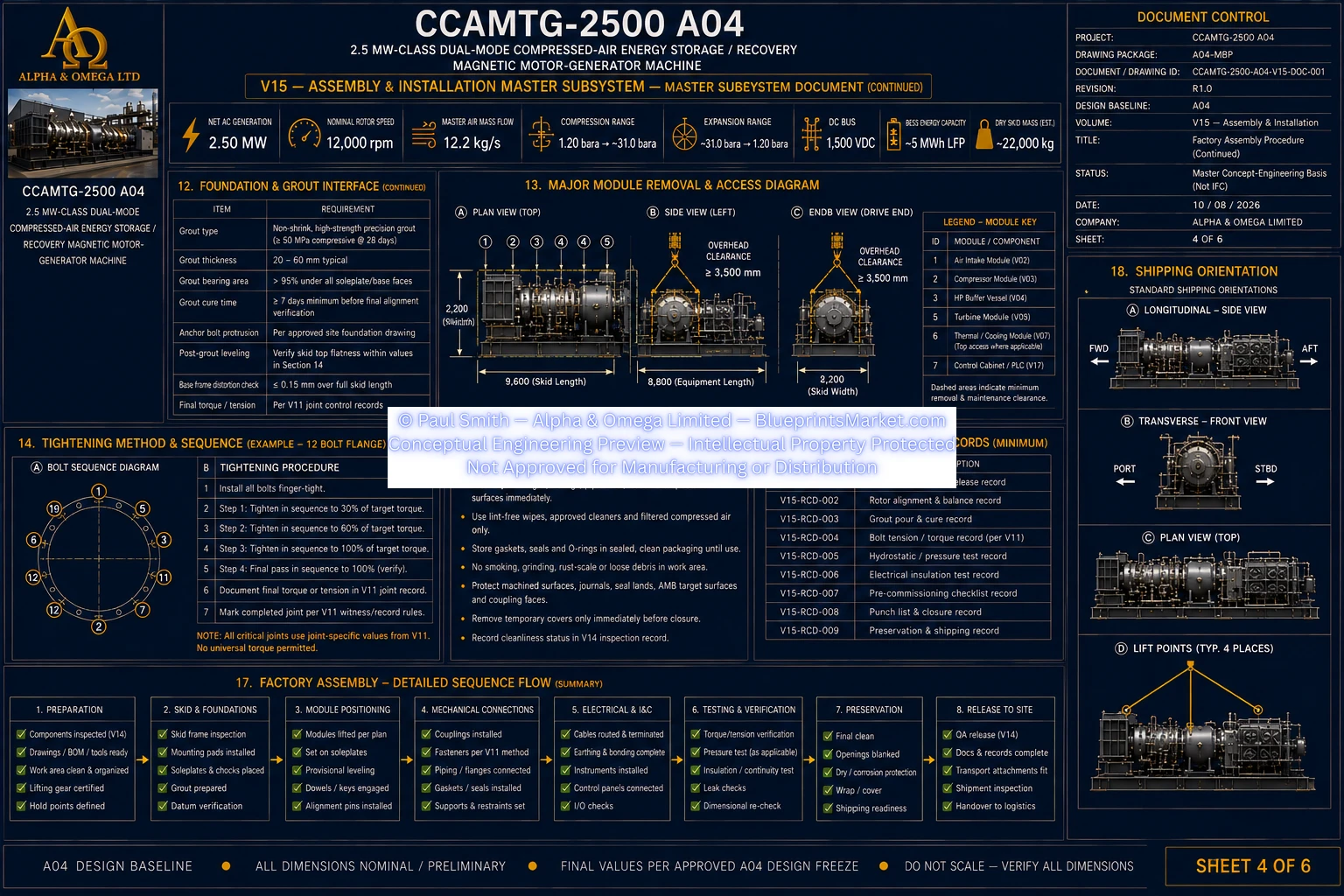
© Paul Smith — Alpha & Omega Limited — PlatformClouds.com — Conceptual Engineering Preview — Not Approved for Manufacturing
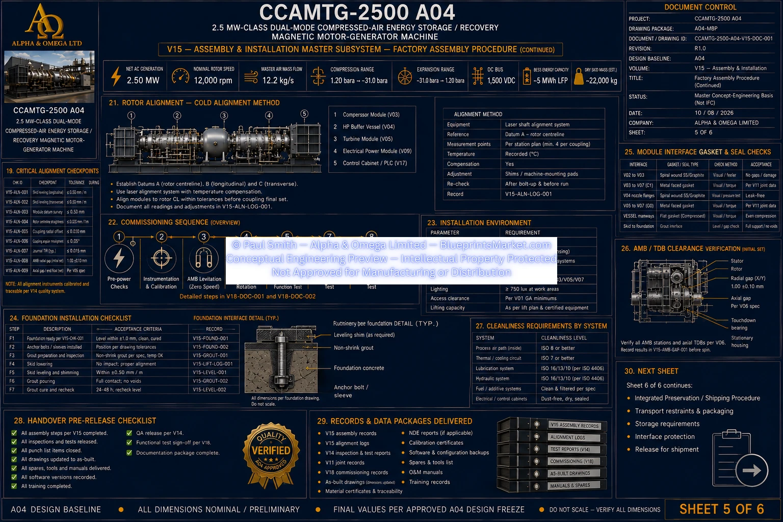
© Paul Smith — Alpha & Omega Limited — PlatformClouds.com — Conceptual Engineering Preview — Not Approved for Manufacturing
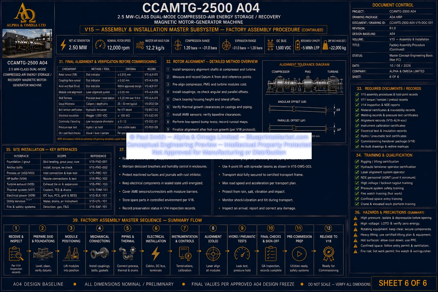
© Paul Smith — Alpha & Omega Limited — PlatformClouds.com — Conceptual Engineering Preview — Not Approved for Manufacturing
V16 — Maintenance, Service & Lifecycle
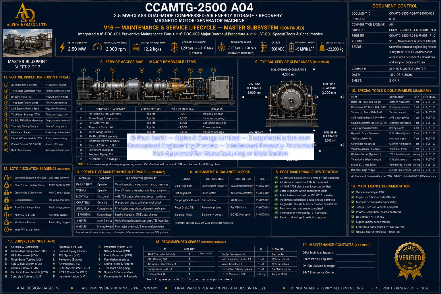
© Paul Smith — Alpha & Omega Limited — PlatformClouds.com — Conceptual Engineering Preview — Not Approved for Manufacturing
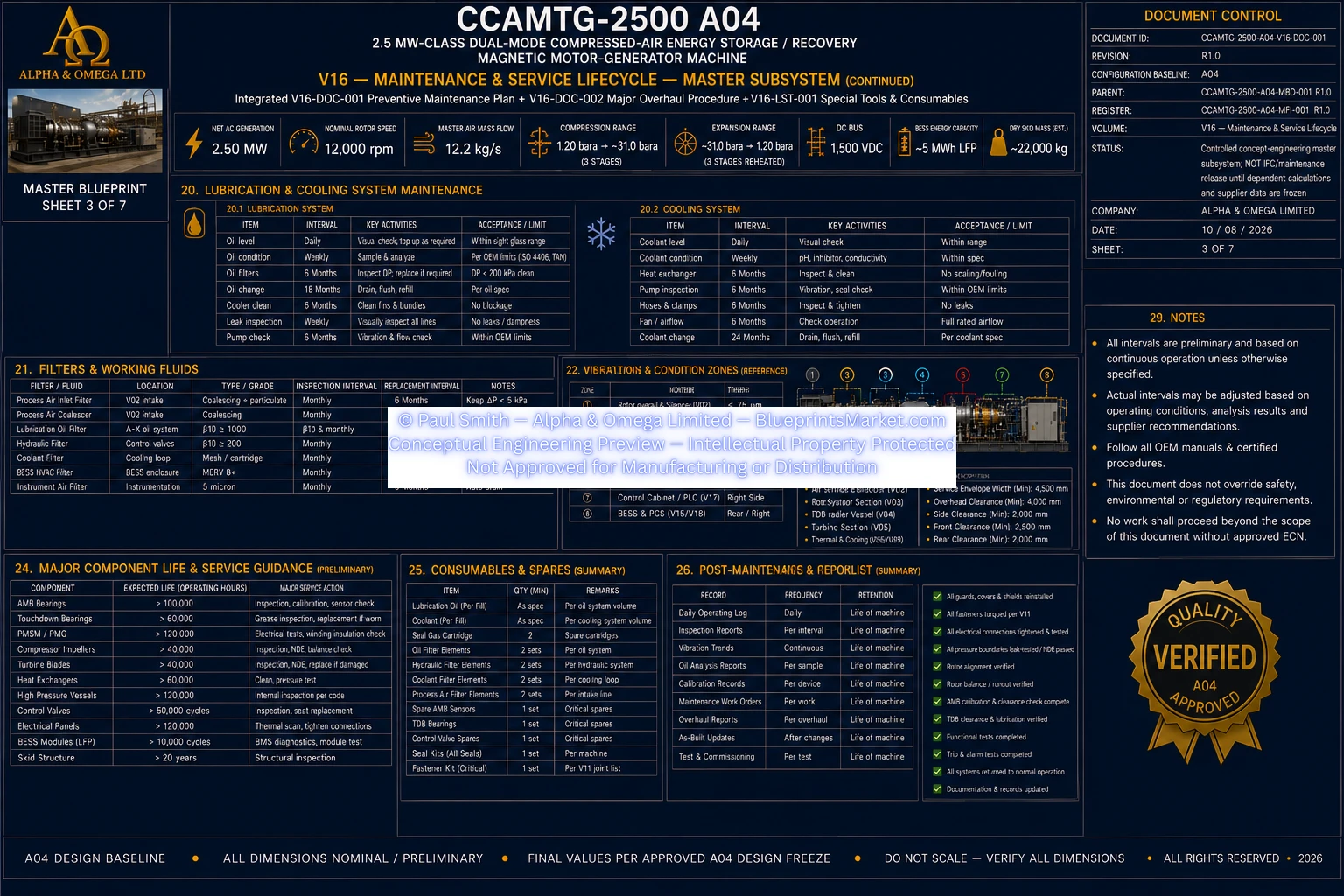
© Paul Smith — Alpha & Omega Limited — PlatformClouds.com — Conceptual Engineering Preview — Not Approved for Manufacturing
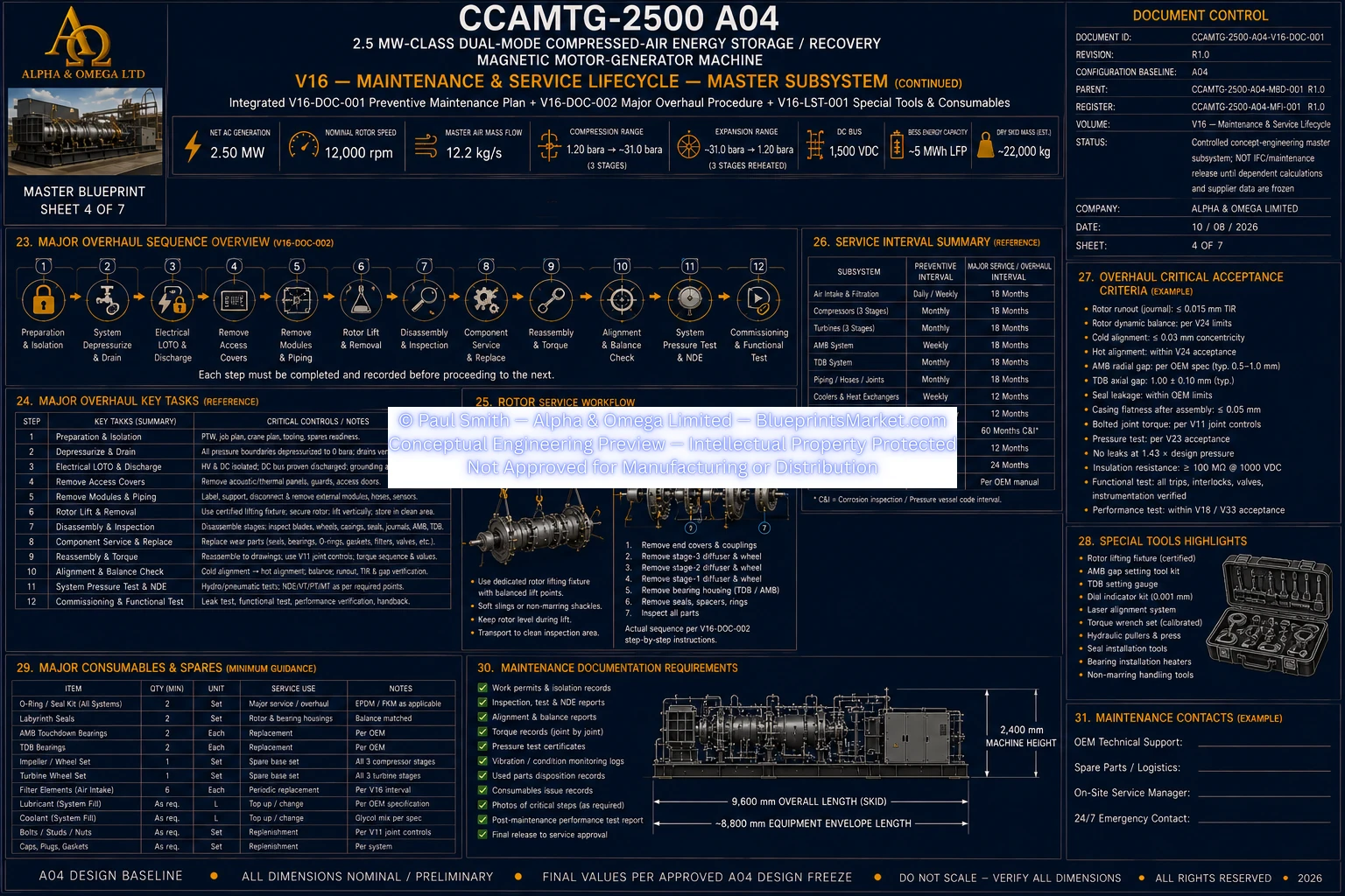
© Paul Smith — Alpha & Omega Limited — PlatformClouds.com — Conceptual Engineering Preview — Not Approved for Manufacturing
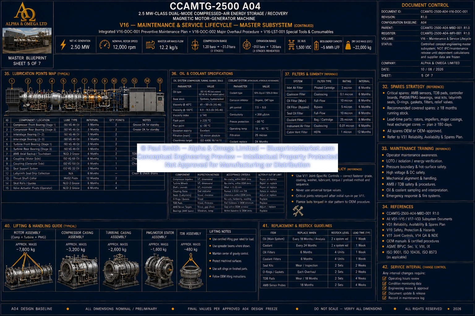
© Paul Smith — Alpha & Omega Limited — PlatformClouds.com — Conceptual Engineering Preview — Not Approved for Manufacturing
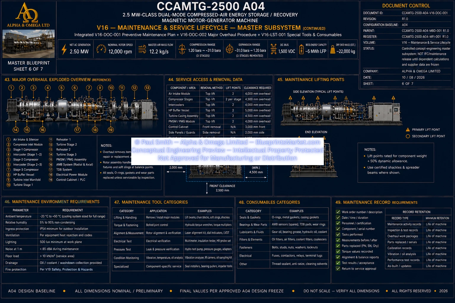
© Paul Smith — Alpha & Omega Limited — PlatformClouds.com — Conceptual Engineering Preview — Not Approved for Manufacturing
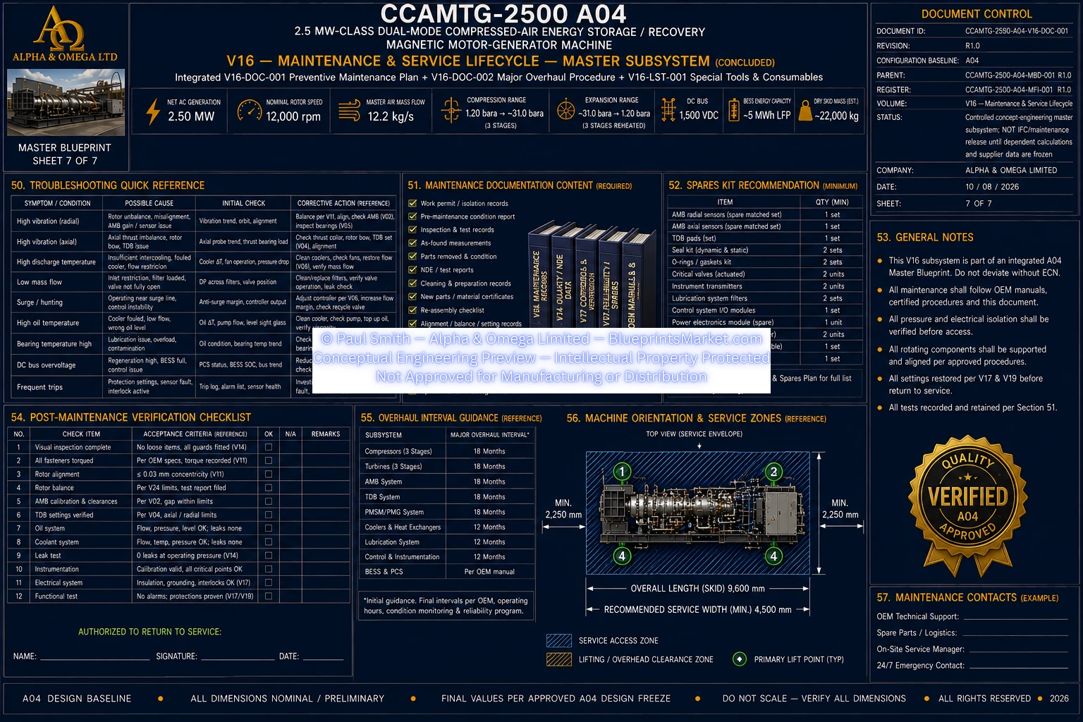
© Paul Smith — Alpha & Omega Limited — PlatformClouds.com — Conceptual Engineering Preview — Not Approved for Manufacturing
V17 — Controls, PLC, SIS, HMI & SCADA
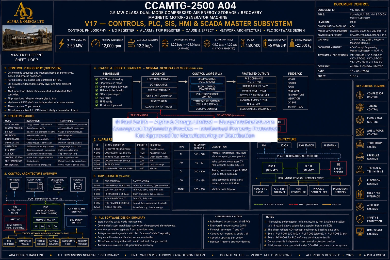
© Paul Smith — Alpha & Omega Limited — PlatformClouds.com — Conceptual Engineering Preview — Not Approved for Manufacturing
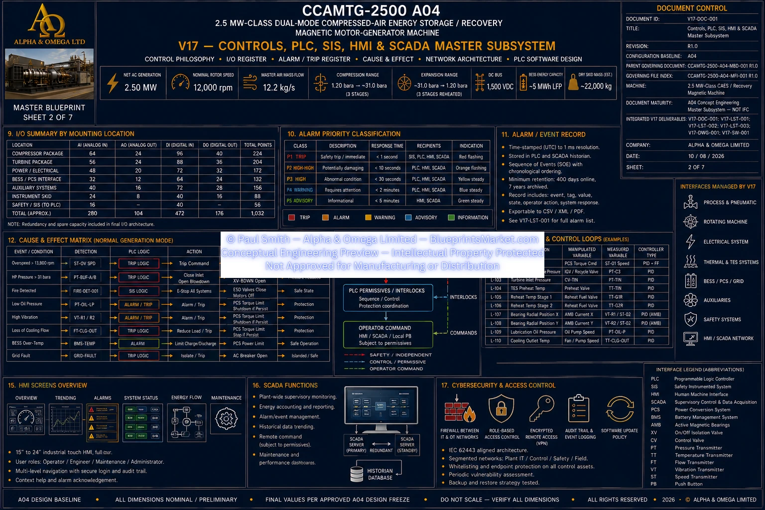
© Paul Smith — Alpha & Omega Limited — PlatformClouds.com — Conceptual Engineering Preview — Not Approved for Manufacturing
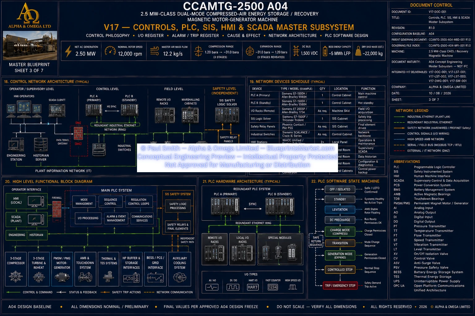
© Paul Smith — Alpha & Omega Limited — PlatformClouds.com — Conceptual Engineering Preview — Not Approved for Manufacturing
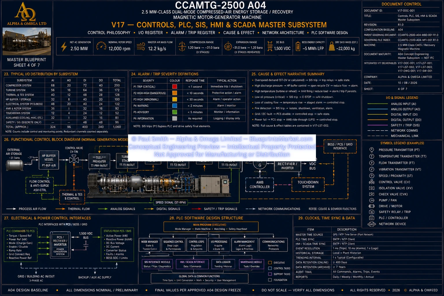
© Paul Smith — Alpha & Omega Limited — PlatformClouds.com — Conceptual Engineering Preview — Not Approved for Manufacturing
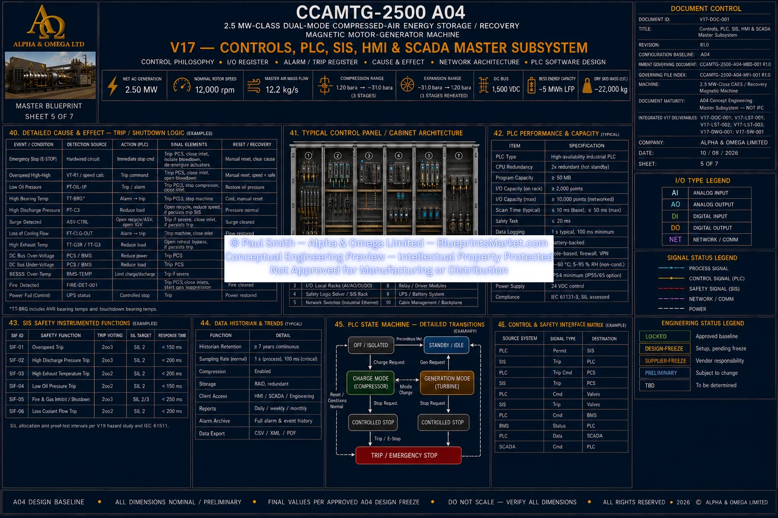
© Paul Smith — Alpha & Omega Limited — PlatformClouds.com — Conceptual Engineering Preview — Not Approved for Manufacturing
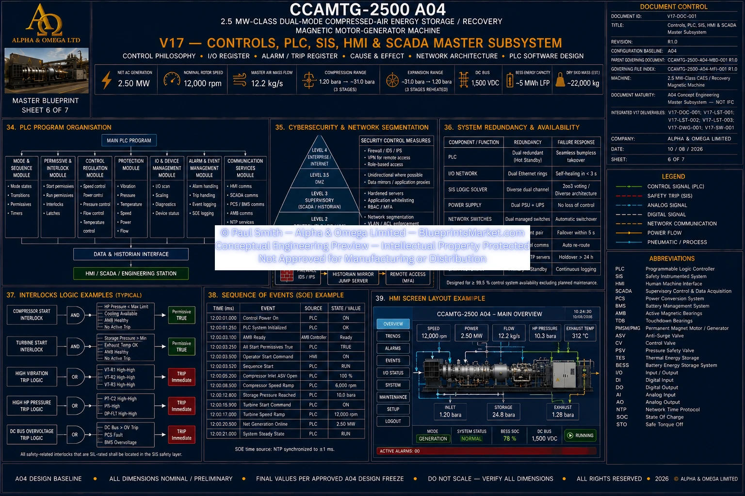
© Paul Smith — Alpha & Omega Limited — PlatformClouds.com — Conceptual Engineering Preview — Not Approved for Manufacturing
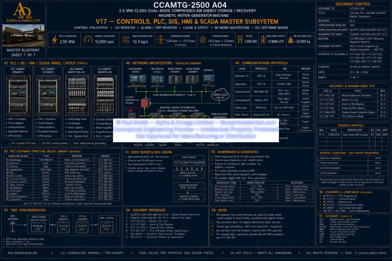
© Paul Smith — Alpha & Omega Limited — PlatformClouds.com — Conceptual Engineering Preview — Not Approved for Manufacturing
