CCAMTG‑2500™ Magnetic Bearing System
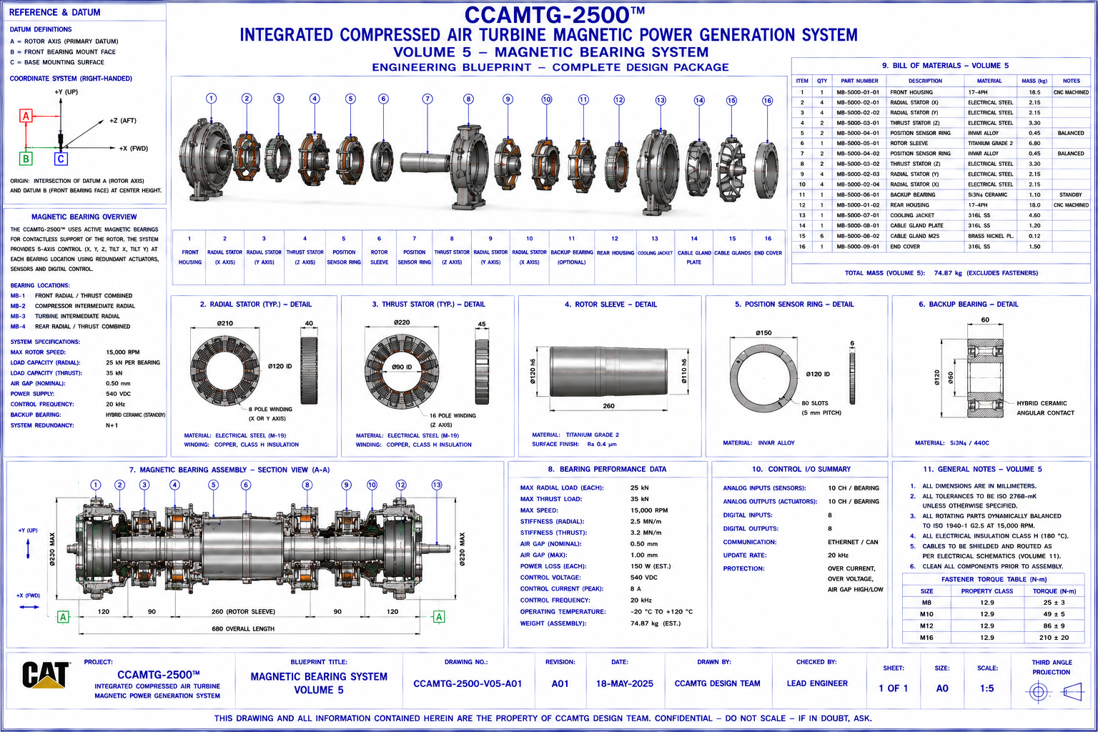
This page presents the engineering documentation for the CCAMTG‑2500™ Magnetic Bearing System
corresponding to Blueprint Volume 06. The magnetic bearing system provides active, non‑contact support
for the rotating shaft assembly, maintaining rotor position through closed‑loop electromagnetic control
while minimizing mechanical wear.
Document Reference
System: CCAMTG‑2500™ Integrated Compressed Air Turbine Magnetic Power Generation System
Volume: 06 — Magnetic Bearing System
Document Number: CAT‑809305‑V06‑DOC‑A03
Revision: A03
Classification: Engineering Concept Documentation
Units: Millimetres (mm), kilograms (kg), amperes (A), volts (V), °C, rpm
Document Purpose
This document provides the engineering description of the CCAMTG‑2500™ Magnetic Bearing System. It
explains subsystem architecture, component functions, sensing, control logic, interfaces, materials,
assembly sequence, and maintenance considerations. It accompanies Blueprint Volume 06 and provides
supporting engineering information for the conceptual design.
System Overview
The magnetic bearing system supports the common rotor assembly shared by the compressor, turbine, and
generator. It provides active, non‑contact shaft support and continuous dynamic stabilization.
Primary objectives include:
- Non‑contact shaft support
- Active radial positioning
- Active axial thrust control
- Reduction of mechanical friction
- High‑speed rotor stability
- Continuous vibration monitoring
- Integration with digital control systems
- Emergency protection during abnormal events
Functional Description
The magnetic bearing system performs the following conceptual functions:
- Levitates the rotor shaft using controlled electromagnetic forces
- Maintains radial and axial shaft position
- Compensates for dynamic loading
- Suppresses rotor vibration
- Monitors shaft displacement in real time
- Interfaces with PLC and magnetic bearing controller
- Transfers fault conditions to the protection system
Magnetic Bearing Architecture
The complete assembly consists of:
- Front Radial Magnetic Bearing
- Rear Radial Magnetic Bearing
- Axial (Thrust) Magnetic Bearing
- Electromagnetic Stator Assemblies
- Laminated Core Packs
- Copper Coil Windings
- Rotor Target Sleeves
- Position Sensors
- Speed Encoder
- Magnetic Bearing Controller
- Power Amplifier Modules
- Current Monitoring Modules
- Cooling Jacket
- Emergency Touchdown Bearings
- Cable Harnesses
- Mounting Frames
- Fastener Package
- Alignment Dowels
All components are identified in Blueprint Volume 06 using exploded‑view callouts and unique part
numbers.
Major Components
Front Radial Magnetic Bearing
- Supports compressor‑end rotor
- Maintains radial shaft position
- Dampens vibration
- Interfaces with bearing controller
Rear Radial Magnetic Bearing
- Supports turbine/generator‑end rotor
- Maintains concentricity
- Stabilizes dynamic rotor motion
- Works with front bearing
Axial (Thrust) Magnetic Bearing
- Controls axial shaft movement
- Counteracts compressor/turbine thrust loads
- Maintains axial rotor position
- Prevents axial contact during transients
Electromagnetic Stators
- Generate controlled magnetic fields
- Produce levitation forces
- Respond to controller commands
- Provide high dynamic response
Rotor Target Sleeves
- Provide magnetic interaction surface
- Maintain concentric geometry
- Interface with displacement sensors
- Support dynamic balancing
Position Sensors
- Measure shaft displacement
- Provide feedback to controller
- Detect vibration
- Support rotor diagnostics
Magnetic Bearing Controller
- Executes closed‑loop control algorithms
- Processes sensor signals
- Commands coil currents
- Interfaces with PLC and HMI
- Generates fault alarms
Emergency Touchdown Bearings
- Protect rotor during power loss
- Prevent catastrophic contact
- Support controlled shutdown
- Minimize damage during fault events
Radial Magnetic Bearings
Each radial bearing assembly includes:
- Laminated magnetic core
- Electromagnetic pole pieces
- Copper windings
- Sensor mounting brackets
- Cooling passages
- Housing
- Cable connectors
Design objectives:
- High stiffness
- Fast response
- Low power loss
- Stable operation
- Minimal rotor displacement
Axial (Thrust) Magnetic Bearing
The thrust bearing assembly comprises:
- Thrust disc
- Electromagnetic stators
- Position sensors
- Housing
- Cooling interface
Primary objectives:
- Precise axial positioning
- Load balancing
- Stable transient response
- Protection against axial overload
Rotor Position Sensing
The position sensing system includes:
- Radial displacement probes
- Axial displacement probes
- Speed encoder
- Vibration monitoring sensors
Measured parameters include:
- X‑axis displacement
- Y‑axis displacement
- Axial position
- Rotor speed
- Vibration amplitude
- Orbit analysis
Bearing Controller Architecture
The controller consists of:
- Digital signal processor (DSP)
- Current amplifiers
- Sensor interface modules
- Redundant power supplies
- Ethernet communications
- PLC interface
- Diagnostic software
- Safety interlocks
Control functions include:
- Closed‑loop PID control
- Fault detection
- Auto‑calibration
- Rotor centering
- System diagnostics
Emergency Backup Bearing System
The touchdown bearing system provides protection during:
- Electrical power loss
- Controller failure
- Excessive shaft displacement
- Emergency shutdown
- Overspeed events
Components include:
- Backup rolling‑element bearings
- Bearing carriers
- Shock absorbers
- Retaining hardware
- Lubrication provision (if applicable)
Cooling System Integration
The magnetic bearing system interfaces with Volume 07 and includes:
- Cooling jackets
- Coolant passages
- Temperature sensors
- Flow monitoring
- Heat removal from coils and amplifiers
Electrical Interfaces
Electrical interfaces include:
- Bearing controller power supply
- Electromagnet power cables
- Position sensor wiring
- Encoder connections
- PLC communications
- Ethernet diagnostics
- Grounding system
- EMC shielding
Related documentation:
- Volume 10 — Electrical Power Generation & Control
- Volume 17 — Control Logic & Automation Architecture
Materials
Representative material selections:
- Bearing Housing: Stainless Steel 316L
- Laminated Core: Silicon Electrical Steel
- Coil Windings: Copper
- Rotor Target Sleeve: High‑Strength Alloy Steel
- Sensor Brackets: Stainless Steel
- Cooling Jacket: Stainless Steel 304
- Touchdown Bearings: Bearing Steel
- Fasteners: Stainless Steel A4‑80
- Cable Insulation: High‑Temperature Polymer
Material selections support electromagnetic performance, thermal stability, structural integrity, and
corrosion resistance within the conceptual operating environment.
Assembly Procedure
Recommended assembly sequence:
- Inspect bearing housings
- Install laminated cores
- Fit electromagnetic coils
- Install cooling jackets
- Install displacement sensors
- Mount thrust bearing assembly
- Install touchdown bearings
- Route wiring harnesses
- Install controller modules
- Perform alignment verification
- Calibrate position sensors
- Verify electrical continuity
Manufacturing Considerations
General manufacturing guidance:
- Precision machine bearing housings
- Grind reference bores
- Machine sensor mounting surfaces
- Assemble laminated cores
- Wind and insulate coils
- Impregnate windings
- Verify magnetic clearances
- Conduct electrical testing
Detailed manufacturing information is provided in Volumes 14, 23, and 24.
Inspection Requirements
Inspection activities include:
- Visual inspection
- Housing dimensional verification
- Air‑gap measurement
- Coil resistance testing
- Insulation resistance testing
- Sensor calibration
- Controller functional testing
- Electrical continuity verification
Maintenance Procedures
Routine maintenance includes:
- Controller diagnostics
- Sensor calibration checks
- Cooling circuit inspection
- Electrical connection inspection
- Backup bearing inspection
- Coil temperature monitoring
- Firmware verification
- System health assessment
Safety Considerations
Before maintenance:
- Isolate electrical power
- Discharge stored electrical energy
- Lock out control systems
- Verify rotor is stationary
- Confirm zero magnetic field
- Follow electrical safety procedures
- Wear appropriate PPE
Design Specifications
The magnetic bearing system is intended to provide:
- Non‑contact rotor support
- Active vibration suppression
- High‑speed rotor stability
- Low maintenance operation
- Integrated diagnostics
- Modular construction
- Redundant protection via touchdown bearings
- Compatibility with compressor, turbine, and generator assemblies
Engineering Reference Data
Associated blueprint: Volume 06 — Magnetic Bearing System
Drawing package includes:
- General Arrangement
- Exploded Assembly
- Radial Bearing Details
- Thrust Bearing Details
- Electromagnetic Coil Layout
- Cross Sections
- Orthographic Views
- Sensor Layout
- Wiring Interfaces
- Bill of Materials
- Dimensioned Reference Drawings
Related Documents
- Volume 01 — Master General Arrangement
- Volume 03 — Compressor Assembly
- Volume 05 — Turbine Assembly
- Volume 07 — Airflow & Cooling System
- Volume 10 — Electrical Power Generation & Control
- Volume 11 — Fastener Package & Assembly Hardware
- Volume 14 — Manufacturing, Inspection & QA
- Volume 17 — Control Logic & Automation Architecture
- Volume 21 — Digital Twin, Simulation & Validation
- Volume 25 — Rotor Dynamics Engineering
- Volume 28 — Electromagnetic Engineering
Document Status
- Document Title: Magnetic Bearing System Engineering Documentation
- Document Number: CAT‑809305‑V06‑DOC‑A03
- Revision: A03
- Classification: Engineering Concept Documentation
- Package: CCAMTG‑2500™ Complete Engineering Blueprint Package
- Associated Blueprint: Volume 06 — Magnetic Bearing System
Conceptual Engineering Package Notice
The Magnetic Bearing System documentation for CCAMTG‑2500™ is provided as conceptual engineering
information. It is intended for design study, modelling, and system integration activities and is not
sufficient by itself to manufacture, certify, or deploy an industrial rotating machine. All real‑world
engineering work must be performed and validated by qualified professionals using detailed
manufacturing drawings, tolerances, and certified component specifications.