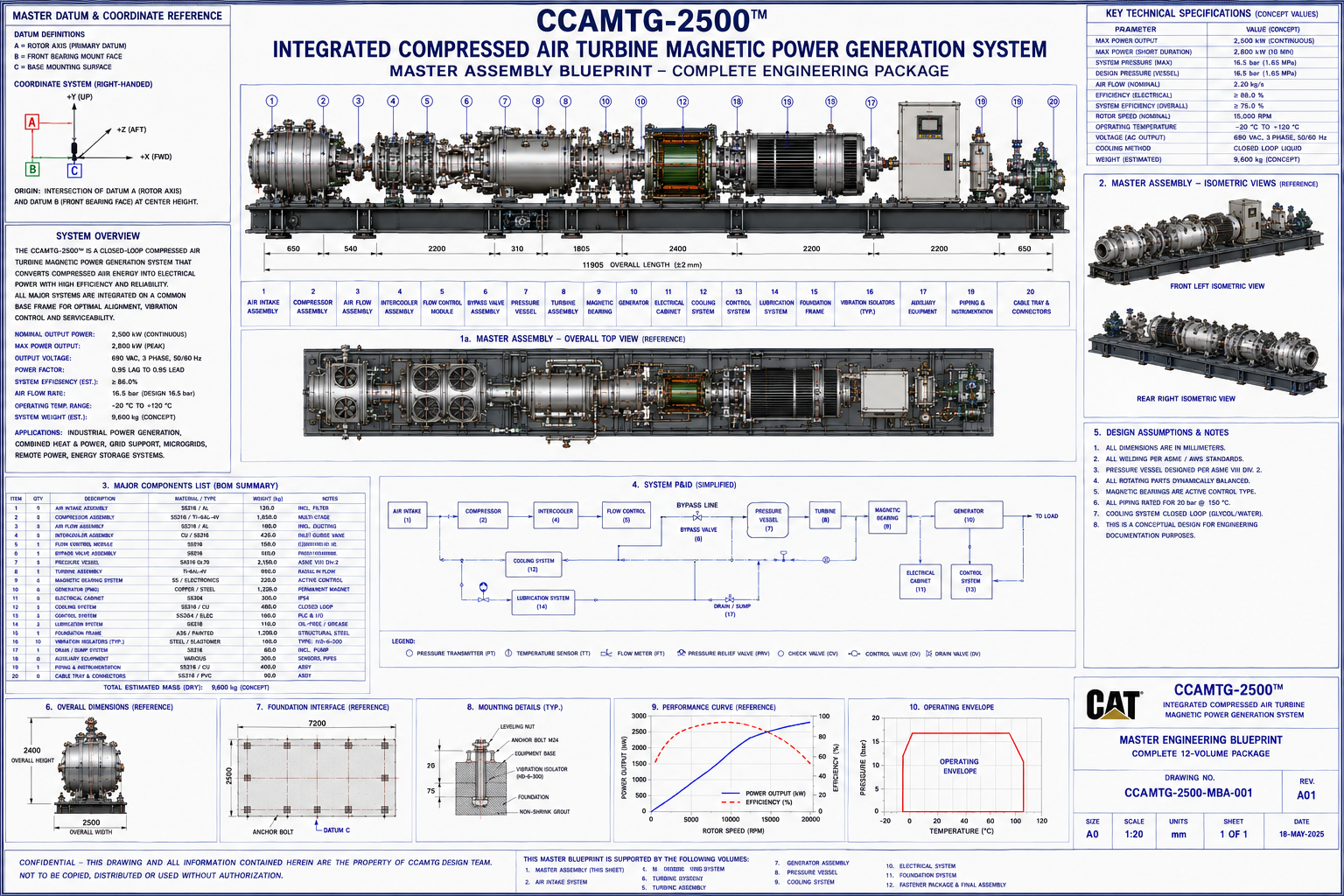
CCAMTG‑2500™ Master General Arrangement (GA)
This page presents the Master General Arrangement (GA) for the CCAMTG‑2500™ Integrated Compressed Air
Turbine Magnetic Power Generation System. It is the controlling reference for the overall architecture,
subsystem interfaces, coordinate systems, and master assembly relationships used across all engineering
volumes.
Document Reference
Volume: 01 — Master General Arrangement (GA)
Document Number: CAT‑809305‑V01‑A03
Revision: A03
System: CCAMTG‑2500™ Integrated Compressed Air Turbine Magnetic Power Generation System
Classification: Engineering Concept Documentation
Units: Millimetres (mm), kilograms (kg), bar(g), °C, kW (where applicable)
Drawing Standard: ISO / ASME CAD Drafting Convention
Sheet Size Reference: A0
Document Purpose
This document is the master engineering reference for the complete CCAMTG‑2500™ system. It establishes
the overall architecture, subsystem interfaces, reference datums, coordinate systems, major dimensions,
design intent, and master assembly relationships used throughout every subsequent engineering volume.
All subsequent volumes reference this document as the controlling master assembly.
System Description
The CCAMTG‑2500™ is a conceptual integrated engineering platform that combines:
- Closed‑loop compressed‑air circulation architecture
- Multi‑stage compression subsystem
- Pressure containment vessel
- Turbine energy conversion stage
- Generator coupling architecture
- Magnetic bearing support system
- Cooling and thermal management
- Electrical generation architecture
- Instrumentation and controls
- Structural support system
The design package is presented as a conceptual engineering documentation set for study, modelling, CAD
development, and system integration. It is not a validated manufacturing design.
Master System Architecture
The overall machine is divided into the following major assemblies:
- Assembly 1000 — Air Intake Module
- Assembly 2000 — Compressor Module
- Assembly 3000 — Pressure Vessel
- Assembly 4000 — Turbine Module
- Assembly 5000 — Generator Module
- Assembly 6000 — Magnetic Bearing System
- Assembly 7000 — Cooling System
- Assembly 8000 — Pipework & Instrumentation
- Assembly 9000 — Electrical Control System
- Assembly 10000 — Structural Base Frame
- Assembly 11000 — Foundation Interface
- Assembly 12000 — Final Machine Assembly
Master Reference Datums & Coordinate System
Primary Datum A: Rotor Centreline
Secondary Datum B: Front Mounting Face
Tertiary Datum C: Base Mounting Plane
Coordinate Axes:
- X — Longitudinal Axis
- Y — Vertical Axis
- Z — Transverse Axis
These datums govern every component throughout the complete engineering package and form the origin for
all coordinate systems used in subsequent volumes.
Master Dimensional Envelope
- Overall Length: Approximately 2,650 mm
- Overall Width: Approximately 1,550 mm
- Overall Height: Approximately 1,900 mm
- Rotor Centre Height: Approximately 950 mm
- Base Frame Width: Approximately 1,450 mm
- Foundation Bolt Pattern: Defined in Volume 09
- Pressure Vessel Diameter: Defined in Volume 04
- Rotor Diameter: Defined in Volume 05
Master Subsystem Interfaces
- Interface I‑01: Air Intake → Compressor (Reference Volume 02)
- Interface I‑02: Compressor → Pressure Vessel (Reference Volume 03)
- Interface I‑03: Pressure Vessel → Turbine (Reference Volume 04)
- Interface I‑04: Turbine → Generator (Reference Volume 05)
- Interface I‑05: Rotor → Magnetic Bearings (Reference Volume 06)
- Interface I‑06: Cooling System (Reference Volume 07)
- Interface I‑07: Pipework (Reference Volume 08)
- Interface I‑08: Foundation (Reference Volume 09)
- Interface I‑09: Electrical Power (Reference Volume 10)
- Interface I‑10: Assembly Hardware (Reference Volume 11)
- Interface I‑11: Final Machine Integration (Reference Volume 12)
Master Bill of Materials (Top Level)
Major assemblies:
- Air Intake Assembly
- Compressor Assembly
- Pressure Vessel Assembly
- Turbine Assembly
- Generator Assembly
- Magnetic Bearing Assembly
- Cooling Assembly
- Instrumentation Assembly
- Electrical Assembly
- Structural Assembly
- Foundation Assembly
- Final Integration Assembly
System Operating Sequence (Conceptual)
Stage 1
- System initialization
- Electrical control system energized
- Control diagnostics complete
Stage 2
- Cooling system starts
- Sensors verified
- Magnetic bearings energized
Stage 3
- Rotor support established
- Compressed‑air circulation initiated
- Pressure stabilization
Stage 4
- Turbine rotation established
- Generator coupling engaged
- Electrical conversion model active
Stage 5
- Continuous monitoring
- Thermal management
- Closed‑loop circulation
- Protective monitoring
Stage 6
- Controlled shutdown
- Rotor deceleration
- Pressure equalization
- Cooling run‑down
- Safe stop
Design Philosophy
The CCAMTG‑2500™ architecture has been organized around:
- Modular subsystem separation
- Independent serviceability
- Consistent datum structure
- Standardized fastener philosophy
- Integrated maintenance access
- Digital engineering compatibility
- Scalable assembly hierarchy
- Revision‑controlled documentation
Drawing Number Structure
Master Drawing: CAT‑809305‑MBA‑A03
Volumes:
- CAT‑809305‑V01
- CAT‑809305‑V02
- …
- CAT‑809305‑V39
Components:
- CAT‑809305‑XX‑001
- CAT‑809305‑XX‑002
- CAT‑809305‑XX‑003
- etc.
Revision Control
- Revision A00: Initial Concept
- Revision A01: Architecture Update
- Revision A02: Subsystem Integration
- Revision A03: Master Engineering Package Release
Related Documents
- Volume 02 — Air Intake System
- Volume 03 — Compressor Assembly
- Volume 04 — Pressure Vessel
- Volume 05 — Turbine Assembly
- Volume 06 — Magnetic Bearing System
- Volume 07 — Airflow & Cooling
- Volume 08 — Piping & Instrumentation
- Volume 09 — Foundation & Structural Installation
- Volume 10 — Electrical Power Generation & Control
- Volume 11 — Fastener Package & Assembly Hardware
- Volume 12 — Final Assembly & Integration
- Volumes 13–39 — Advanced engineering documentation, manufacturing, analysis, validation, and reference manuals.
General Notes
- All dimensions are reference unless otherwise specified.
- Coordinate systems originate from Datum A.
- Interface geometry is controlled by the respective subsystem volumes.
- All subsequent drawings shall reference this master arrangement.
-
This documentation represents a conceptual engineering package intended for design study, CAD
modelling, and system integration activities. It is not sufficient by itself to manufacture or certify
a working industrial machine.
Conceptual Engineering Package Notice
The Master General Arrangement (GA) for CCAMTG‑2500™ is provided as conceptual engineering
documentation. It defines architecture, interfaces, and reference geometry for design study and system
integration. It does not constitute a validated manufacturing design or certified industrial machine.