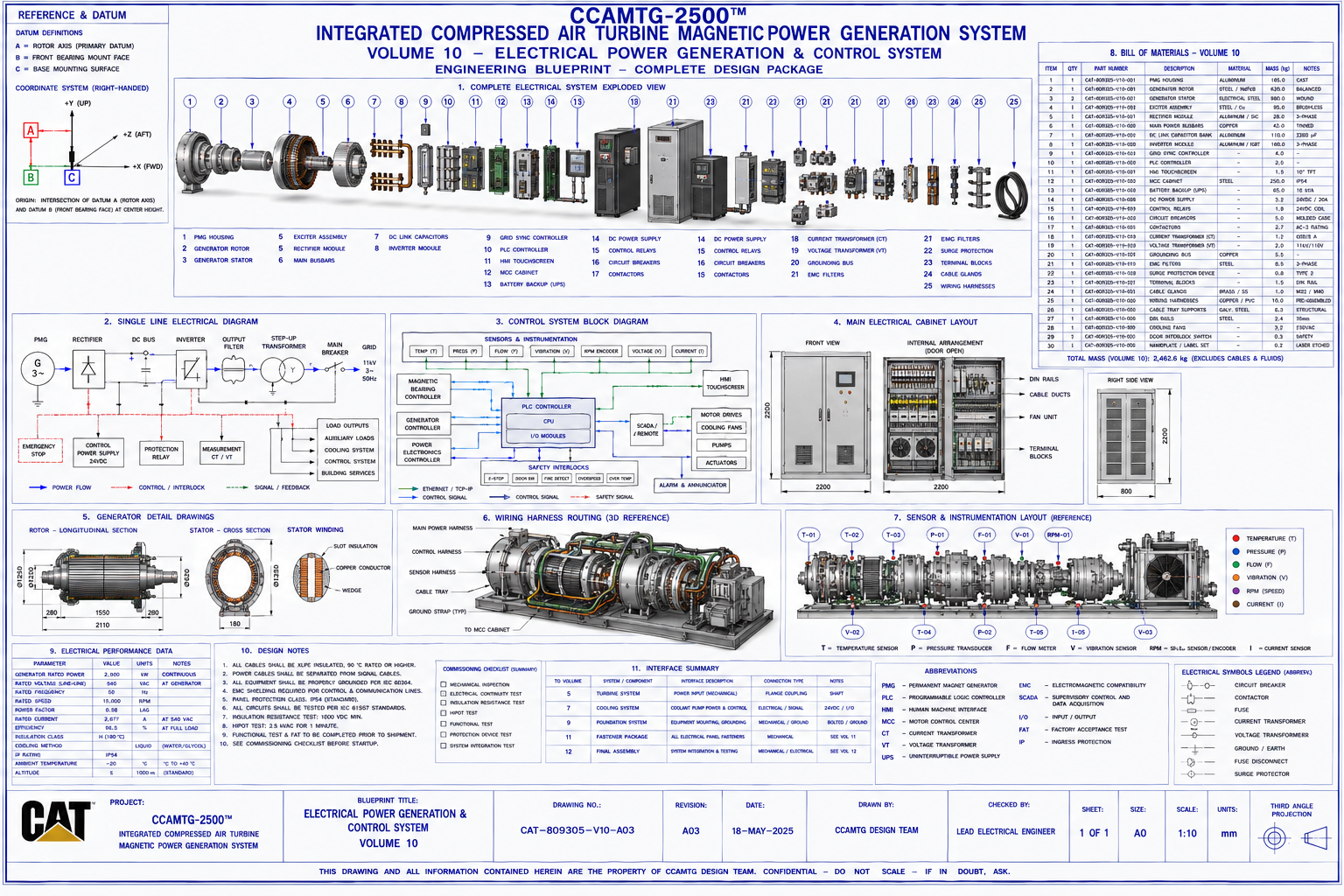
CCAMTG‑2500™ Electrical Power Generation & Control System
This page presents the engineering documentation for the CCAMTG‑2500™ Electrical Power Generation &
Control System corresponding to Blueprint Volume 10. The electrical system converts turbine shaft power
into usable electrical energy while monitoring, protecting, and controlling all machine functions through
a fully integrated automation architecture.
Document Reference
System: CCAMTG‑2500™ Integrated Compressed Air Turbine Magnetic Power Generation System
Volume: 10 — Electrical Power Generation & Control System
Document Number: CAT‑809305‑V10‑DOC‑A03
Revision: A03
Classification: Engineering Concept Documentation
Units: V, A, Hz, W, kW, MW, mm, °C
Document Purpose
This document provides the engineering description of the CCAMTG‑2500™ Electrical Power Generation &
Control System. It explains subsystem architecture, component functions, power conversion, automation,
protection systems, interfaces, materials, assembly sequence, and maintenance considerations. It
accompanies Blueprint Volume 10 and provides supporting engineering information for the conceptual
design.
System Overview
The electrical system integrates the following major assemblies:
- Permanent Magnet Generator (PMG)
- Generator Rotor & Stator
- Exciter Assembly
- Rectifier Module
- DC Link Capacitor Bank
- Inverter Module
- Main Power Busbars
- Main MCC (Motor Control Centre)
- PLC Controller
- HMI Touchscreen
- SCADA Interface
- Battery Backup (UPS)
- DC Power Supplies
- Protection Relays
- Circuit Breakers & Contactors
- Current & Voltage Transformers
- EMC Filters
- Surge Protection Devices
- Grounding System
- Wiring Harnesses, Cable Trays & Junction Boxes
Functional Description
The electrical system performs the following conceptual functions:
- Converts turbine mechanical power into electrical power
- Conditions generated power for controlled distribution
- Monitors all operating parameters
- Controls compressor, turbine, cooling, and auxiliary systems
- Provides operator interface and diagnostics
- Executes automatic shutdown sequences under fault conditions
- Interfaces with external electrical loads or grid connection
- Logs operational data for diagnostics and digital twin integration
Electrical System Architecture
Power Generation
- Permanent Magnet Generator
- Rotor & Stator
- Exciter
Power Conversion
- Rectifier
- DC Bus
- Capacitor Bank
- Inverter
- Transformer
- Output Breaker
Automation
- PLC
- Remote I/O
- HMI
- SCADA
- Ethernet Switches
Protection
- Overcurrent Protection
- Earth Fault Protection
- Surge Protection
- Emergency Shutdown
- Overspeed Protection
- Thermal Protection
Permanent Magnet Generator (PMG)
The generator assembly consists of:
- Rotor
- Stator
- Shaft Coupling
- Cooling Jacket
- End Shields
- Bearings
- Terminal Box
- Temperature Sensors
Primary functions:
- Convert rotational energy into electrical energy
- Maintain stable voltage output
- Operate across specified speed range
- Provide high efficiency under varying load conditions
Power Conversion System
Power conversion stages include:
- Generator Output
- Three‑Phase Rectifier
- DC Link
- Capacitor Bank
- PWM Inverter
- Output Transformer
- Main Distribution Bus
Objectives:
- Stable voltage regulation
- Frequency control
- Harmonic reduction
- Efficient power conversion
- Grid or load compatibility
Main Electrical Distribution
The distribution system includes:
- Main Busbars
- Incoming Breaker
- Generator Breaker
- Auxiliary Supply
- UPS Distribution
- Motor Feeders
- Instrument Power Supply
- Control Power Supply
- Ground Fault Monitoring
PLC & Automation Control System
Automation components include:
- PLC CPU
- Remote I/O Modules
- Analog Inputs & Outputs
- Digital Inputs & Outputs
- Safety PLC
- Communication Gateways
Primary control functions:
- Compressor control
- Turbine regulation
- Magnetic bearing control interface
- Cooling management
- Alarm management
- Shutdown sequencing
HMI & SCADA Integration
Operator interface provides:
- Live process overview
- Alarm display
- Historical trending
- Maintenance notifications
- Diagnostic tools
- Parameter adjustment
- User authentication
- Data logging
SCADA interfaces support:
- Ethernet/IP
- Profinet
- Modbus TCP
- OPC‑UA
- Industrial VPN (where applicable)
Instrumentation & Sensor Network
The electrical system receives inputs from:
Temperature
- Generator windings
- Bearings
- Cooling system
- Cabinet temperature
- Inverter temperature
Pressure
- Air system
- Cooling circuit
Mechanical
- Shaft speed
- Rotor displacement
- Vibration
- Magnetic bearing position
Electrical
- Voltage
- Current
- Frequency
- Power factor
- Active & Reactive power
- Harmonic distortion
Electrical Cabinet Layout
Main MCC cabinet includes:
- Incoming section
- Generator protection
- PLC rack
- UPS
- Terminal blocks
- DC power supplies
- Ethernet switches
- Cable ducts
- Cooling fans
- Ventilation filters
Cabinet layout emphasizes:
- Ease of maintenance
- Cable segregation
- Thermal management
- Accessibility
Cable Management System
Cable infrastructure includes:
- Power cable trays
- Control cable trays
- Fibre optic routing
- Instrument wiring
- Shielded communication cables
- Flexible cable chains
- Junction boxes
- Cable glands
- Identification markers
Grounding & Earthing
The grounding system includes:
- Main earth bus
- Generator grounding
- Cabinet grounding
- Structural grounding
- Instrument earth
- Shield grounding
- Lightning protection interface
Objectives:
- Personnel protection
- Equipment protection
- EMC compliance
- Fault current dissipation
Electrical Protection Systems
Protection functions include:
- Overcurrent
- Short circuit
- Ground fault
- Overvoltage
- Undervoltage
- Reverse power
- Overspeed
- Overtemperature
- Phase imbalance
- Frequency deviation
Emergency Shutdown (ESD)
The ESD system performs:
- Generator isolation
- Turbine shutdown
- Compressor unloading
- Cooling continuation
- Alarm notification
- Data logging
- Safe machine stop
Emergency stop stations are located at:
- Main operator panel
- MCC cabinet
- Turbine enclosure
- Maintenance platform
Assembly Procedure
Recommended installation sequence:
- Install MCC cabinet
- Mount generator
- Install PLC hardware
- Route cable trays
- Install power cables
- Install control wiring
- Connect instrumentation
- Install grounding system
- Verify insulation resistance
- Configure PLC
- Commission HMI
- Perform functional testing
Manufacturing Considerations
General manufacturing guidance:
- Assemble electrical panels
- Install DIN rails
- Wire terminal blocks
- Fabricate wiring harnesses
- Label all conductors
- Verify panel layout
- Conduct factory wiring inspection
- Perform dielectric testing
Detailed manufacturing information is provided in Volumes 14, 24, and 32.
Inspection & Testing
Inspection activities include:
- Visual inspection
- Wiring continuity
- Insulation resistance testing
- Earth continuity testing
- Functional testing
- PLC verification
- Generator testing
- Protection relay testing
- Communication verification
- Factory Acceptance Testing (FAT)
Maintenance Procedures
Routine maintenance includes:
- Cabinet cleaning
- Terminal torque verification
- Cooling fan inspection
- Battery testing
- PLC backup verification
- Firmware updates
- Generator inspection
- Cable inspection
- Grounding verification
Safety Considerations
Before electrical work:
- Isolate all power sources
- Lock‑Out/Tag‑Out (LOTO)
- Verify zero voltage
- Discharge capacitors
- Use insulated tools
- Wear arc‑flash PPE
- Verify grounding
- Follow electrical safety procedures
Design Specifications
The electrical system is intended to provide:
- High‑efficiency power conversion
- Reliable automation
- Industrial‑grade electrical protection
- Comprehensive monitoring
- Modular maintenance
- Safe emergency shutdown
- Digital twin compatibility
- Industrial communication capability
These specifications define the conceptual electrical performance targets for the CCAMTG‑2500™ system.
All real‑world implementations require detailed electrical engineering, protection studies, regulatory
compliance, and certified component specifications.
Engineering Reference Data
Associated blueprint: Volume 10 — Electrical Power Generation & Control System
Drawing package includes:
- Electrical General Arrangement
- Single Line Diagram (SLD)
- Control Block Diagram
- Generator Assembly
- MCC Cabinet Layout
- Wiring Harness Layout
- Instrumentation Layout
- Cable Routing
- Bill of Materials
- Dimensioned Reference Drawings
Related Documents
- Volume 01 — Master General Arrangement
- Volume 05 — Turbine Assembly
- Volume 06 — Magnetic Bearing System
- Volume 07 — Airflow & Cooling System
- Volume 08 — Piping & Instrumentation
- Volume 09 — Foundation & Structural Installation
- Volume 11 — Fastener Package & Assembly Hardware
- Volume 12 — Final Assembly & Integration
- Volume 17 — Control Logic & Automation Architecture
- Volume 21 — Digital Twin, Simulation & Validation
- Volume 28 — Electromagnetic Engineering Package
- Volume 30 — Instrumentation Package
- Volume 32 — PLC Software Architecture
Document Status
- Document Title: Electrical Power Generation & Control System Engineering Documentation
- Document Number: CAT‑809305‑V10‑DOC‑A03
- Revision: A03
- Classification: Engineering Concept Documentation
- Package: CCAMTG‑2500™ Complete Engineering Blueprint Package
- Associated Blueprint: Volume 10 — Electrical Power Generation & Control System
Conceptual Engineering Package Notice
The Electrical Power Generation & Control System documentation for CCAMTG‑2500™ is provided as
conceptual engineering information. It is intended for design study, modelling, and system integration
activities and is not sufficient by itself to manufacture, certify, or deploy an industrial
power‑generation system. All real‑world engineering work must be performed and validated by qualified
professionals using detailed electrical schematics, protection studies, regulatory compliance, and
certified component specifications.