CCAMTG‑2500™ Air Intake System
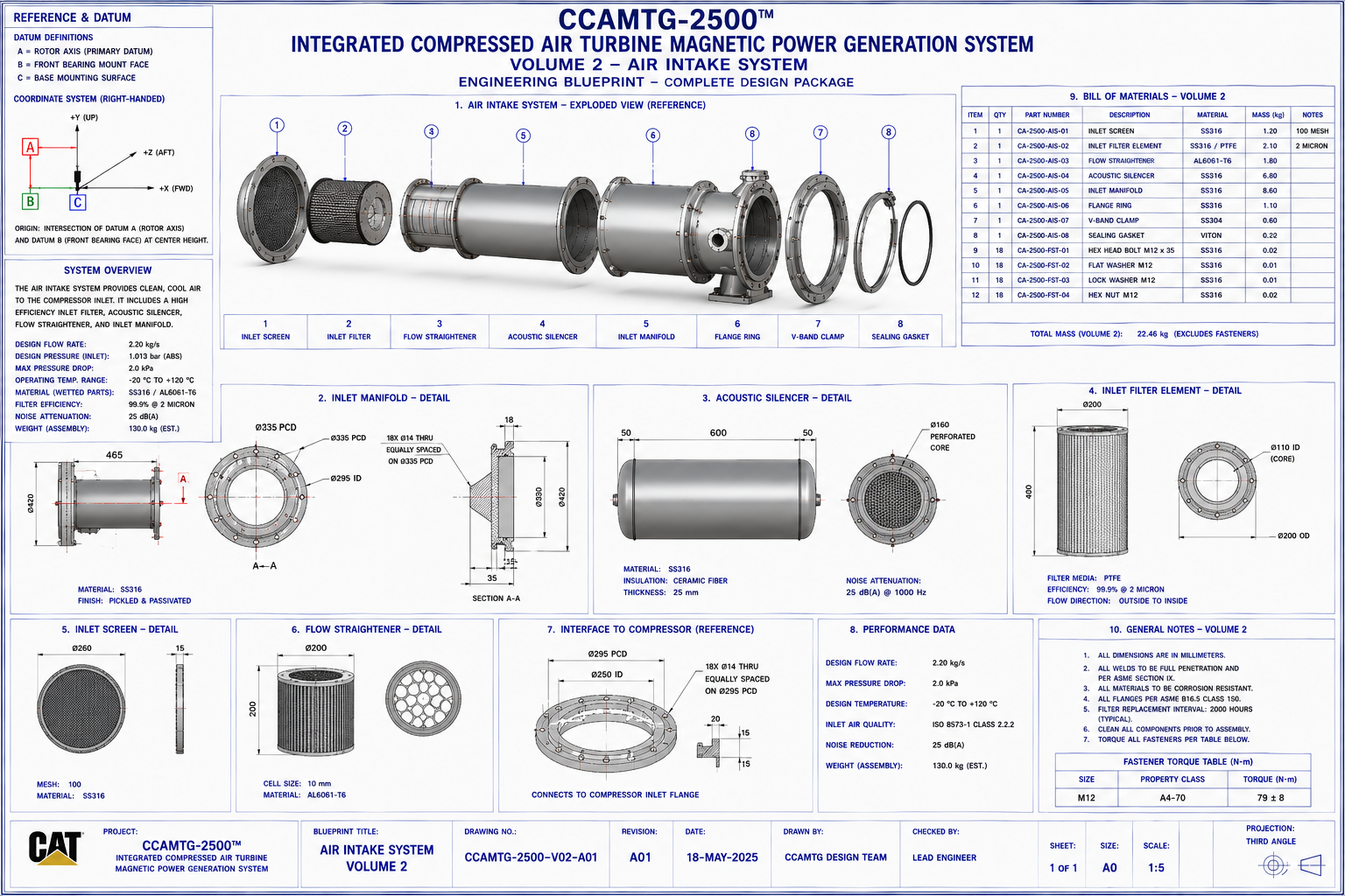
This page presents the engineering documentation for the CCAMTG‑2500™ Air Intake System corresponding to
Blueprint Volume 02. It describes the purpose, operating principles, components, interfaces, and design
intent for the conceptual air intake assembly within the integrated compressed‑air turbine magnetic power
generation system.
Document Reference
System: CCAMTG‑2500™ Integrated Compressed‑Air Turbine Magnetic Power Generation System
Volume: 02 — Air Intake System
Document Number: CAT‑809305‑V02‑DOC‑A03
Revision: A03
Classification: Engineering Concept Documentation
Units: Millimetres (mm)
Prepared By: CCAMTG Design Team
Document Purpose
This document provides the engineering description of the CCAMTG‑2500™ Air Intake System corresponding
to Blueprint Volume 02. It explains the purpose, operating principles, interfaces, components,
materials, and engineering considerations for the conceptual air intake assembly. It is intended to
accompany the associated A0 engineering blueprint sheet and provide descriptive context for the
illustrated design.
System Overview
The Air Intake System forms the primary airflow entry into the closed‑loop compressed‑air system. It
conditions and directs working air toward the compressor inlet while minimizing pressure losses and
supporting stable flow distribution.
Primary objectives include:
- Controlled airflow entry
- Uniform flow distribution
- Filtration of incoming air (where applicable)
- Pressure containment
- Structural support for adjoining compressor interfaces
- Accommodation of thermal expansion and sealing requirements
Functional Description
The intake assembly is designed to:
- Receive process air from the closed‑loop circulation path
- Direct airflow into the compressor inlet
- Maintain uniform velocity profiles
- Reduce turbulence entering the compressor
- Minimize pressure drop
- Support instrumentation and monitoring points
- Maintain pressure integrity within the conceptual system architecture
Air Intake Assembly
The primary assembly comprises:
- Air Intake Manifold
- Intake Ring
- Inlet Nozzle Ring
- Mounting Flanges
- O‑Ring Sealing Interfaces
- Fastener Sets
- Alignment Dowels
- Inspection Ports
- Drain Connections
- Instrumentation Tappings
Each component is identified within Blueprint Volume 02 using exploded assembly balloons and referenced
part numbers.
Component Description
Air Intake Manifold
Primary pressure‑retaining component that distributes incoming airflow uniformly around the intake
circumference.
Functions:
- Pressure containment
- Flow equalization
- Structural mounting
- Instrument attachment
Intake Ring
Provides concentric alignment between manifold and compressor inlet.
Functions:
- Mechanical alignment
- Seal compression
- Load transfer
- Interface stability
Inlet Nozzle Ring
Directs airflow toward the compressor eye with optimized geometry intended to reduce inlet turbulence.
Functions:
- Velocity conditioning
- Flow guidance
- Pressure recovery
- Compressor inlet transition
Sealing Components
Static sealing elements include:
- O‑Rings
- Face seals
- Flange gaskets
Purpose:
- Pressure retention
- Leakage reduction
- Thermal expansion accommodation
Fasteners
Typical fastener package:
- Stainless steel bolts
- Hex nuts
- Hardened washers
- Alignment dowels
Refer to Volume 11 for detailed hardware specifications.
Airflow Path
Airflow sequence:
- Closed‑loop return → Intake manifold → Intake ring → Nozzle ring → Compressor inlet
Design intent:
- Smooth transition
- Uniform velocity profile
- Reduced separation
- Minimal recirculation zones
Mechanical Design
The intake assembly is designed to:
- Support internal pressure loads
- Maintain concentricity with the compressor
- Resist vibration
- Provide service accessibility
- Enable modular disassembly
Interfaces are flange‑mounted with dowel‑assisted alignment to support repeatable assembly and
consistent geometry.
Materials
Representative material selections:
- Intake Manifold: Stainless Steel 316
- Intake Ring: Stainless Steel 316
- Nozzle Ring: Titanium Alloy Ti‑6Al‑4V
- Bolts: Stainless Steel
- Washers: Stainless Steel
- O‑Rings: Fluoroelastomer (FKM)
- Dowels: Stainless Steel
Material choices are intended to support corrosion resistance, structural integrity, and compatibility
with the conceptual operating environment.
Interfaces
The Air Intake System interfaces directly with:
- Volume 01 — Master General Arrangement
- Volume 03 — Compressor Assembly
- Volume 07 — Airflow & Cooling System
- Volume 08 — Piping & Instrumentation
- Volume 11 — Fastener Package
Assembly Information
Recommended assembly sequence:
- Install intake manifold
- Fit alignment dowels
- Position intake ring
- Install sealing elements
- Mount nozzle ring
- Insert fasteners
- Torque fasteners in cross pattern
- Verify concentricity
- Perform leak inspection
Manufacturing Notes
General manufacturing considerations:
- Machine flange faces to specified flatness
- Deburr all machined edges
- Clean sealing surfaces prior to assembly
- Inspect threaded features
- Verify bore concentricity
- Passivate stainless steel components after machining where applicable
Inspection Requirements
Inspection activities include:
- Visual inspection
- Dimensional verification
- Bore diameter measurement
- Flange flatness check
- Bolt hole positional inspection
- Surface finish verification
- Seal groove inspection
- Leak testing following assembly
Maintenance
Routine maintenance recommendations:
- Inspect seals during scheduled shutdowns
- Verify fastener torque
- Inspect flange interfaces for corrosion or damage
- Clean intake passages
- Replace sealing components if deterioration is observed
Safety
Engineering considerations:
- Depressurize system prior to maintenance
- Verify isolation of connected equipment
- Inspect lifting points before handling
- Follow applicable pressure vessel safety procedures
- Use appropriate personal protective equipment
Design Specifications
Design intent includes:
- Stable airflow distribution
- Modular construction
- Ease of maintenance
- Pressure integrity
- Structural rigidity
- Compatibility with adjoining compressor assembly
- Support for instrumentation integration
Engineering Reference Data
Associated blueprint: Volume 02 — Air Intake System
Associated drawings include:
- Exploded assembly
- Orthographic views
- Cross‑sections
- Dimensioned component drawings
- Interface details
- Bill of Materials
- Assembly views
Related Drawings
- Volume 01 — Master General Arrangement
- Volume 03 — Compressor Assembly
- Volume 07 — Airflow & Cooling System
- Volume 08 — Piping & Instrumentation
- Volume 11 — Fastener Package
- Volume 12 — Final Assembly & Integration
Document Status
- Document Title: Air Intake System Engineering Documentation
- Document Number: CAT‑809305‑V02‑DOC‑A03
- Revision: A03
- Classification: Engineering Concept Documentation
- Package: CCAMTG‑2500™ Complete Engineering Blueprint Package
- Associated Blueprint: Volume 02 — Air Intake System
Conceptual Engineering Package Notice
The Air Intake System documentation for CCAMTG‑2500™ is provided as conceptual engineering
information. It is intended for design study, modelling, and system integration activities and is not
sufficient by itself to manufacture or certify a working industrial machine.