FOS‑P1 — Fiber‑Optic Smart Phone S1
Mechanical & Structural Architecture (MBP‑001 — R1.0)
Purpose & Scope
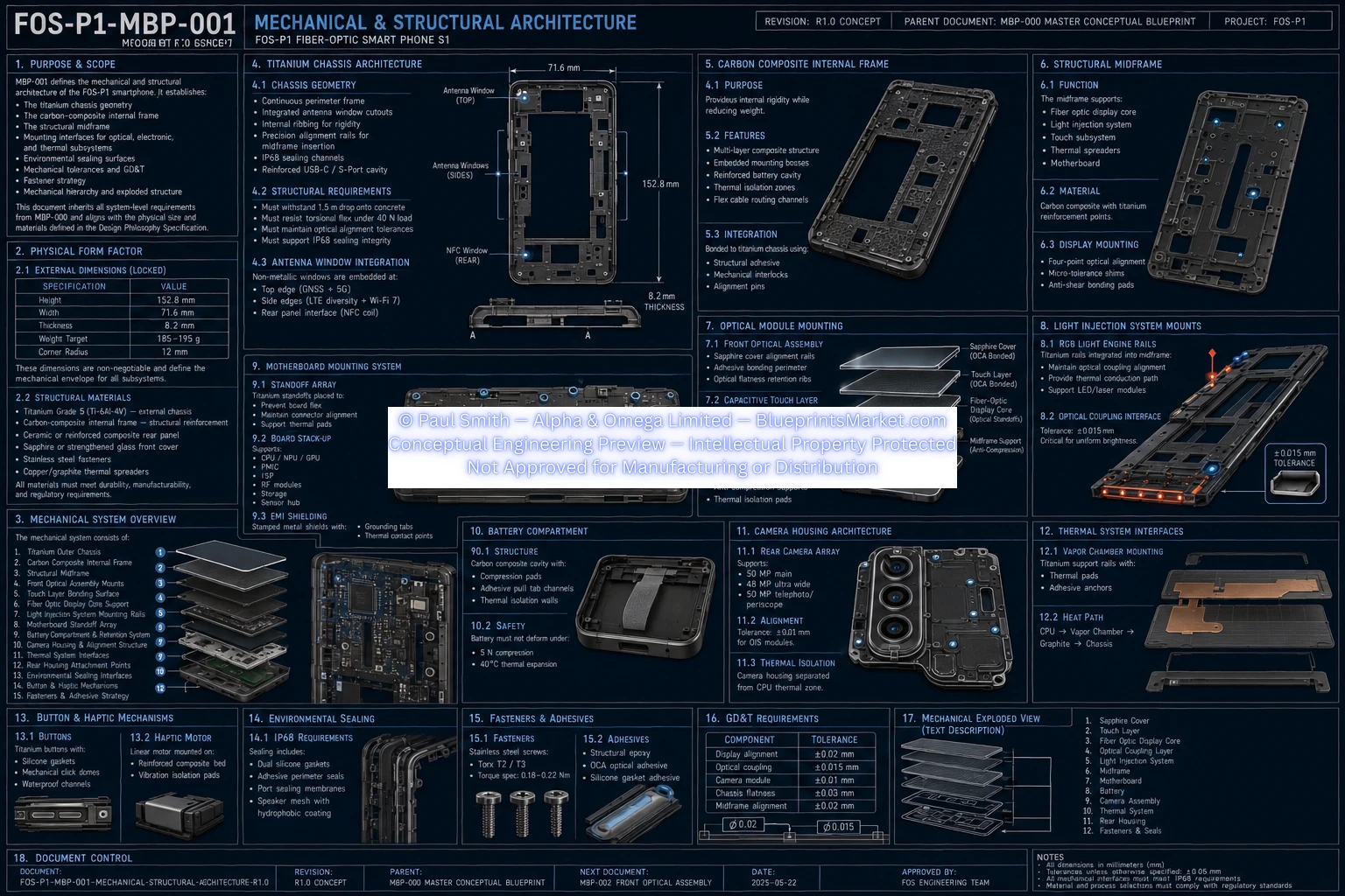
MBP‑001 defines the complete mechanical and structural architecture of the FOS‑P1 smartphone. As stated in the specification, it establishes the titanium chassis geometry, carbon‑composite internal frame, structural midframe, subsystem mounting interfaces, environmental sealing surfaces, GD&T tolerances, fastener strategy, and the full mechanical hierarchy of the device.
This subsystem inherits all system‑level requirements from MBP‑000 and aligns with the physical size, materials, and design intent defined in the Master Conceptual Blueprint.
Physical Form Factor
External Dimensions (Locked)
| Specification | Value |
|---|---|
| Height | 152.8 mm |
| Width | 71.6 mm |
| Thickness | 8.2 mm |
| Weight Target | 185–195 g |
| Corner Radius | 12 mm |
These dimensions are non‑negotiable and define the mechanical envelope for all subsystems.
Structural Materials
- Titanium Grade 5 (Ti‑6Al‑4V) — external chassis
- Carbon‑composite internal frame
- Ceramic or reinforced composite rear panel
- Sapphire or strengthened glass front cover
- Stainless steel fasteners
- Copper/graphite thermal spreaders
Mechanical System Overview
The mechanical system consists of:
- Titanium Outer Chassis
- Carbon Composite Internal Frame
- Structural Midframe
- Front Optical Assembly Mounts
- Touch Layer Bonding Surface
- Fiber‑Optic Display Core Support
- Light Injection System Mounting Rails
- Motherboard Standoff Array
- Battery Compartment & Retention System
- Camera Housing & Alignment Structure
- Thermal System Interfaces
- Rear Housing Attachment Points
- Environmental Sealing Interfaces
- Button & Haptic Mechanisms
- Fasteners & Adhesive Strategy
Titanium Chassis Architecture
Chassis Geometry
- CNC‑machined titanium perimeter frame
- Integrated antenna window cutouts
- Internal ribbing for rigidity
- Precision alignment rails for midframe insertion
- IP68 sealing channels
- Reinforced USB‑C / S‑Port cavity
Structural Requirements
- Must withstand 1.5 m drop onto concrete
- Must resist torsional flex under 40 N load
- Must maintain optical alignment tolerances
- Must support IP68 sealing integrity
Antenna Window Integration
- Top edge — GNSS + 5G
- Side edges — LTE diversity + Wi‑Fi 7
- Rear panel interface — NFC coil
Carbon Composite Internal Frame
Purpose
Provides internal rigidity while reducing weight.
Features
- Multi‑layer composite structure
- Embedded mounting bosses
- Reinforced battery cavity
- Thermal isolation zones
- Flex‑cable routing channels
Integration
- Structural adhesive
- Mechanical interlocks
- Alignment pins
Structural Midframe
Function
- Supports fiber‑optic display core
- Supports light injection system
- Supports touch subsystem
- Supports thermal spreaders
- Supports motherboard
Material
Carbon composite with titanium reinforcement points.
Display Mounting
- Four‑point optical alignment
- Micro‑tolerance shims
- Anti‑shear bonding pads
Optical Module Mounting
Front Optical Assembly
- Sapphire cover alignment rails
- Adhesive bonding perimeter
- Optical flatness retention ribs
Capacitive Touch Layer
- Bonded using optically clear adhesive (OCA)
- Controlled thickness tolerance (±0.02 mm)
Fiber‑Optic Display Core
- Precision optical standoffs
- Anti‑compression supports
- Thermal isolation pads
Light Injection System Mounts
RGB Light Engine Rails
- Titanium rails integrated into midframe
- Maintain optical coupling alignment
- Provide thermal conduction path
- Support LED/laser modules
Optical Coupling Interface
Tolerance: ±0.015 mm (critical for uniform brightness).
Motherboard Mounting System
Standoff Array
- Prevents board flex
- Maintains connector alignment
- Supports thermal pads
Board Stack‑Up
- CPU / GPU / NPU
- PMIC
- ISP
- RF modules
- Storage
- Sensor hub
EMI Shielding
- Stamped metal shields
- Grounding tabs
- Thermal contact points
Battery Compartment
Structure
- Carbon‑composite cavity
- Compression pads
- Adhesive pull‑tab channels
- Thermal isolation walls
Safety
- Battery must not deform under 5 N compression
- Battery must tolerate 40°C thermal expansion
Camera Housing Architecture
Rear Camera Array
- 50 MP main
- 48 MP ultra‑wide
- 50 MP telephoto/periscope
Alignment
Tolerance: ±0.01 mm for OIS modules.
Thermal Isolation
Camera housing separated from CPU thermal zone.
Thermal System Interfaces
Vapor Chamber Mounting
- Titanium support rails
- Thermal pads
- Adhesive anchors
Heat Path
CPU → Vapor Chamber → Graphite → Chassis
Button & Haptic Mechanisms
Buttons
- Titanium buttons
- Silicone gaskets
- Mechanical click domes
- Waterproof channels
Haptic Motor
- Linear motor
- Reinforced composite mounting bed
- Vibration isolation pads
Environmental Sealing
IP68 Requirements
- Dual silicone gaskets
- Adhesive perimeter seals
- Port sealing membranes
- Hydrophobic speaker mesh
Fasteners & Adhesives
Fasteners
- Stainless steel screws
- Torx T2/T3
- Torque spec: 0.18–0.22 Nm
Adhesives
- Structural epoxy
- OCA optical adhesive
- Silicone gasket adhesive
GD&T Requirements
| Component | Tolerance |
|---|---|
| Display alignment | ±0.02 mm |
| Optical coupling | ±0.015 mm |
| Camera module | ±0.01 mm |
| Chassis flatness | ±0.03 mm |
| Midframe alignment | ±0.02 mm |
Mechanical Exploded View (Text Description)
- Sapphire Cover
- Touch Layer
- Fiber‑Optic Display Core
- Optical Coupling Layer
- Light Injection System
- Midframe
- Motherboard
- Battery
- Camera Assembly
- Thermal System
- Rear Housing
- Fasteners & Seals
Document Control
- Document: FOS‑P1‑MBP‑001‑MECHANICAL‑STRUCTURAL‑ARCHITECTURE‑R1.0
- Revision: R1.0 Concept
- Parent: MBP‑000
- Next Document: MBP‑002 — Front Optical Assembly
FOS‑P1 Commercial Manufacturing License
The FOS‑P1 Fiber‑Optic Smart Phone S1 is licensed as a premium conceptual engineering system. This license grants manufacturers the right to produce, distribute, and sell real-world implementations of the FOS‑P1 architecture while ensuring full copyright protection, global royalty enforcement, and long-term conceptual IP ownership retained by the Licensor.
View Full License AgreementLicensing & Royalty Pricing Structure
| License Type | Commercial Manufacturing License |
| One‑Time License Fee | USD $5,000,000 |
| Royalty Rate | 8% per unit sold worldwide |
| Term | 5 Years (Mandatory Renewal) |
| Ownership | Licensor retains 100% copyright & IP |
| Patents | All patents & derivative patents prohibited |
| Sublicensing | Strictly prohibited |
| Reporting & Audits | Quarterly reporting & mandatory audit compliance |
Commercial Manufacturing License Agreement
This Commercial Manufacturing License Agreement (“Agreement”) governs the rights and obligations between the Licensor (Blueprints Market / Paul Geoffrey Smith) and the Licensee (the purchasing manufacturer). By purchasing the FOS‑P1 Conceptual Engineering Package, the Licensee agrees to the following legally binding terms:
1. Grant of License
The Licensor grants the Licensee a non‑exclusive, non‑transferable, non‑sublicensable right to manufacture, distribute, and sell physical products derived from the FOS‑P1 conceptual engineering system for a period of five (5) years, subject to mandatory renewal.
2. Intellectual Property Ownership
The Licensor retains full and exclusive ownership of all conceptual engineering designs, blueprints, documentation, system architecture, and derivative works. No transfer of ownership is granted under this Agreement.
3. Royalty Obligations
The Licensee agrees to pay a royalty of eight percent (8%) of the wholesale price for every unit manufactured, distributed, or sold worldwide that incorporates any portion of the FOS‑P1 conceptual engineering system, whether in whole or in part.
4. Reporting Requirements
The Licensee must submit quarterly sales reports detailing units manufactured, units sold, wholesale pricing, and total royalty amounts owed. Failure to report constitutes a breach of Agreement.
5. Audit Rights
The Licensor reserves the right to conduct independent audits of the Licensee’s manufacturing and sales records to verify compliance. The Licensee must provide full access to relevant documentation upon request.
6. Patent Restrictions
The Licensee is strictly prohibited from filing patents, patent applications, or derivative patents based on any portion of the FOS‑P1 conceptual engineering system. Any attempt to patent the system or its derivatives constitutes immediate termination of the Agreement.
7. Sublicensing Restrictions
The Licensee may not sublicense, transfer, lease, or otherwise distribute the conceptual engineering package or any portion thereof to third parties.
8. Global Enforcement
This Agreement is enforceable worldwide. Any unauthorized use, reproduction, or distribution of the conceptual engineering system will result in legal action, damages, and immediate termination of the License.
9. Renewal
Renewal of this Agreement is mandatory every five (5) years. Renewal fees and updated royalty terms may apply based on market conditions and technological advancements.
Why This Technology Matters
The FOS‑P1 represents a breakthrough in smartphone engineering. Its multimode fiber‑optic display core, titanium structural chassis, multi‑camera imaging system, advanced thermal architecture, secure software stack, and modular subsystem design make it a next‑generation platform for premium mobile devices. Manufacturers who adopt this system gain access to a world‑first conceptual architecture capable of generating multi‑billion‑dollar product lines.
How to License the FOS‑P1 System
To obtain the Commercial Manufacturing License, manufacturers must contact Blueprints Market directly. Licensing for the FOS‑P1 Fiber‑Optic Smart Phone S1 is handled on a case‑by‑case basis, including full verification, contractual review, and compliance assessment. Once approved, the Licensee receives the complete Master Blueprint Package (MBP‑000 → MBP‑030), commercial manufacturing rights, and access to ongoing conceptual engineering updates.
Blueprint Image Set — FOS‑P1
High‑resolution engineering blueprint sheets for the complete fiber‑optic smartphone system.