FOS‑WDP‑S1 — Mechanical & Structural Architecture
MBP‑001 — Master Blueprint Package
Fiber‑Optic Smart Wall Display Panel
System Overview
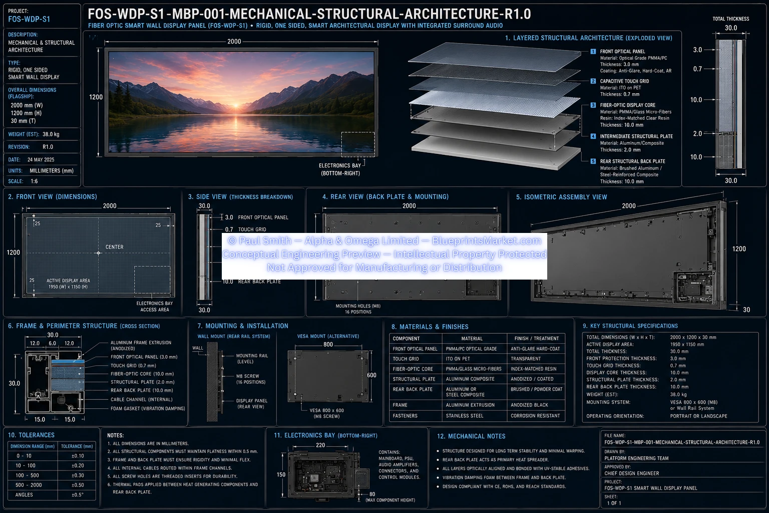
The Mechanical & Structural Architecture defines the complete physical construction of the FOS‑WDP‑S1 Fiber‑Optic Smart Wall Display Panel. This subsystem specifies all structural layers, materials, chassis design, mounting interfaces, mechanical tolerances, service access points, and integration requirements for manufacturing.
- High structural rigidity
- Minimal weight
- Excellent heat dissipation
- Long service life
- Low panel flex
- Precise optical alignment
- Easy serviceability
- Professional architectural installation
Global Dimensions
- Width: 2000 mm
- Height: 1200 mm
- Overall Thickness: 30.0 mm
- Configuration: Rigid one‑sided display panel
- Orientation: Landscape or Portrait
- Estimated Mass: ~38 kg
Front Assembly
Front Optical Panel
- Material: Optical Grade PMMA / Polycarbonate Composite
- Thickness: 3.0 mm
- Surface Finish: Hard Coat
- Anti‑Glare & Anti‑Reflective Layers
- UV Resistant & Scratch Resistant
- Function: Primary optical viewing surface
Capacitive Touch Layer
- Material: ITO on PET film
- Thickness: 0.7 mm
- Touch Type: Projected Capacitive Multi‑Touch
- Interface: I²C Touch Controller
- Controller Location: Main Electronics Bay
Display Core Structure
Fiber‑Optic Display Core
- Material: PMMA / Glass Micro‑Fibre Matrix
- Resin: Index‑matched UV‑stable optical resin
- Thickness: 10.0 mm
- Function: Uniform light transport, pixel distribution, scene rendering
Light Injection Modules
- Placement: Top & Bottom Edges
- Technology: High‑brightness RGB LEDs or RGB Laser Arrays
- Cooling: Micro heatsinks & thermal pads
- Interface: Flexible printed circuits
- Driver: Constant‑current driver ICs
- Control: CPU‑controlled brightness, colour & rendering
Structural Layers
Intermediate Structural Plate
- Material: Aluminium Composite
- Thickness: 2.0 mm
- Purpose: Reinforcement, alignment, mounting, cable routing
Rear Structural Back Plate
- Material: Aluminium or Steel‑Reinforced Composite
- Thickness: 10.0 mm
- Functions: Main chassis, heat spreader, mounting interface, electronics enclosure
Frame Assembly
- Material: Extruded Aluminium
- Finish: Black Anodised
- Integrated cable channels
- Hidden fasteners
- Rear service access
- Corner reinforcement
- Architectural low‑profile finish
Mechanical Layer Stack
- Layer 1 — Front Optical Panel (3.0 mm)
- Layer 2 — Capacitive Touch Layer (0.7 mm)
- Layer 3 — Fiber‑Optic Display Core (10.0 mm)
- Layer 4 — Intermediate Structural Plate (2.0 mm)
- Layer 5 — Rear Structural Back Plate (10.0 mm)
- Total Assembly Thickness: 30.0 mm
Rear Mounting System
- Supported Mounts: VESA, Rear Rail, Wall Bracket, Architectural Mount
- VESA Pattern: 800 × 600 mm
- Thread Type: M8
- Total Mounting Positions: 16
- Material: Steel Thread Inserts
Electronics Bay
- Location: Bottom‑Right Rear
- Size: 220 mm × 150 mm
- Contains: Mainboard, PSU, Amplifiers, Connectors, Distribution, Firmware Access
Materials
| Component | Material |
|---|---|
| Front Panel | Optical Grade PMMA / PC |
| Touch Layer | ITO on PET |
| Display Core | PMMA / Glass Fibre |
| Structural Plate | Aluminium Composite |
| Rear Plate | Aluminium / Steel Composite |
| Frame | Extruded Aluminium |
| Mount Inserts | Stainless Steel |
| Fasteners | Stainless Steel |
Tolerances
| Dimension Range | Tolerance |
|---|---|
| 0–10 mm | ±0.10 mm |
| 10–100 mm | ±0.20 mm |
| 100–500 mm | ±0.30 mm |
| 500–2000 mm | ±0.50 mm |
| Angular | ±0.5° |
Thermal Management
- Primary Heat Spreader: Rear Structural Back Plate
- Heat Sources: CPU, PSU, LED Modules, Amplifiers
- Cooling: Passive conduction, thermal pads, natural convection
- Optional: Upper ventilation slots
Serviceability
The structural design allows servicing of all major electronics without removing the front optical assembly:
- Mainboard
- Power Supply
- Audio Amplifiers
- Connectors
- Sensors
- Wireless Modules
- LED Driver Assemblies
Installation Requirements
- Orientation: Landscape or Portrait
- Wall Surface: Flat, rigid, level
- Fastener Type: M8
- Installation Method: Rear Rail or VESA Bracket
Manufacturing Sequence
- Manufacture perimeter frame
- Machine rear structural plate
- Install threaded inserts
- Manufacture intermediate plate
- Cast fiber‑optic display core
- Bond core to structural plate
- Laminate touch layer
- Bond front optical panel
- Install LED/laser modules
- Install cable routing
- Install electronics bay
- Install PSU
- Install mainboard
- Install audio system
- Install sensors
- Install wireless antennas
- Install rear plate
- Complete fastening
- Dimensional inspection
- Structural inspection
- Thermal verification
- Final QA
Design Requirements
- Maximum structural stiffness
- Accurate optical alignment
- Stable thermal characteristics
- Low vibration
- Dimensional stability
- Architectural appearance
- Full service accessibility
- Manufacturing repeatability
Blueprint Access & Licensing
MBP‑001 — Mechanical & Structural Architecture is part of the complete multi‑volume engineering blueprint package for the FOS‑WDP‑S1 Fiber‑Optic Smart Wall Display Panel.
Contact Blueprints Market for licensing, integration support or enterprise‑level deployment.