FOS‑WDP‑S1 — Power Supply Subsystem
MBP‑010 — Master Blueprint Package
Fiber‑Optic Smart Wall Display Panel
System Overview
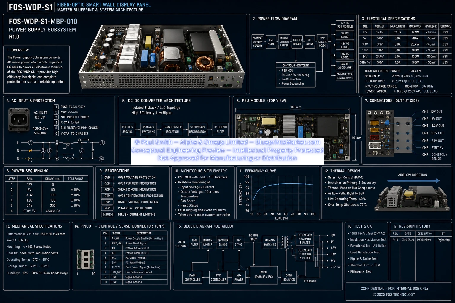
The Power Supply Subsystem (PSU) converts AC mains input into multiple regulated DC rails for the FOS‑WDP‑S1 display system. It provides high efficiency, low ripple, controlled power sequencing, digital monitoring, and comprehensive protection for long‑term reliability.
The architecture uses an isolated Flyback / LLC topology with active PFC, digital telemetry, and PMBus support.
Power Flow Architecture
- AC Input
- EMI Filter
- Inrush Current Limiter
- Rectifier Bridge
- Power Factor Correction (PFC)
- Main Isolated DC/DC Converter
- Regulated DC Outputs
Control & Monitoring
- PSU MCU
- PMBus / I²C Monitoring
- Fault Protection
- Power Sequencing
Electrical Specifications
| Rail | Voltage | Max Current | Max Power | Ripple (P‑P) | Tolerance |
|---|---|---|---|---|---|
| 12V | 12.0 V | 12.0 A | 144 W | <120 mV | ±3% |
| 5V | 5.0 V | 8.0 A | 40 W | <50 mV | ±3% |
| 3.3V | 3.3 V | 8.0 A | 26.4 W | <40 mV | ±3% |
| 1.8V | 1.8 V | 5.0 A | 9.0 W | <30 mV | ±3% |
| 24V | 24.0 V | 5.0 A | 120 W | <200 mV | ±3% |
| Standby 5V | 5.0 V | 1.0 A | 5.0 W | <50 mV | ±3% |
- Total Output Power: ≈344.4 W
- Efficiency: ≥92% @ 230 VAC, 50% Load
- Hold‑Up Time:>20 ms
- Input Voltage: 100–240 VAC
- Power Factor: ≥0.95
AC Input & Protection
- IEC C14 Power Inlet
- 100–240 VAC, 50/60 Hz
Protection Components
- Fuse T6.3AL / 250V
- MOV 275VAC
- NTC Inrush Limiter
- X‑Cap (0.47 µF)
- EMI Filter (CM/DM Choke)
- Y‑Cap to Chassis
DC‑DC Converter Architecture
- Isolated Flyback / LLC Converter
- High Efficiency
- Low Ripple
Power Path
- PFC Bus (380V DC)
- Primary Switching
- Transformer Isolation
- Secondary Rectification
- LC Output Filtering
Feedback provided via opto‑isolated control loop.
PSU Module
| Parameter | Value |
|---|---|
| Length | 180 mm |
| Width | 90 mm |
Major Assemblies
- Input filtering stage
- Transformer
- Primary heatsinks
- Secondary rectifiers
- Cooling fan
- Output connector block
Output Connectors
| Connector | Function |
|---|---|
| CN1 | 12V Output |
| CN2 | 5V Output |
| CN3 | 3.3V Output |
| CN4 | 1.8V Output |
| CN5 | 24V Output |
| CN6 | Standby 5V |
| CN7 | Control / Sense |
Power Sequencing
| Step | Rail | Delay |
|---|---|---|
| 1 | 12V | 0 ms |
| 2 | 5V | 50 ms |
| 3 | 3.3V | 100 ms |
| 4 | 1.8V | 150 ms |
| 5 | 24V | 200 ms |
| 6 | Standby 5V | Always On |
Switched rail tolerance: ±10%
Protection Features
- Over Voltage Protection (OVP)
- Over Current Protection (OCP)
- Short Circuit Protection (SCP)
- Over Temperature Protection (OTP)
- Under Voltage Protection (UVP)
- Power Failure Protection (PFP)
- Inrush Current Limiting
Monitoring & Telemetry
- Input Voltage & Current
- Output Voltages & Currents
- Temperature
- Fan Speed
- Fault Status
- Event Logging
Communication
- PMBus
- I²C Interface
Efficiency
- Peak efficiency: 92–93%
- Highest efficiency at 50–70% load
- Stable efficiency across operating range
Thermal Design
- PWM Smart Cooling Fan
- Primary & Secondary Heatsinks
- Thermal Pads
- Directed Right‑to‑Left Airflow
- Max Operating Temp: 60°C
- Thermal Shutdown: 75°C
Mechanical Specifications
| Parameter | Value |
|---|---|
| Dimensions | 180 × 90 × 40 mm |
| Weight | 0.65 kg |
| Mounting | 4 × M3 Screws |
| Chassis | Steel Ventilation Slots |
| Operating Temperature | 0°C to 60°C |
| Storage Temperature | −20°C to 85°C |
| Humidity | 10–90% RH |
Control / Sense Connector (CN7)
| Pin | Signal | Description |
|---|---|---|
| 1 | PS_ON | Power Supply Enable |
| 2 | PWR_OK | Power Good |
| 3 | A0 | PMBus Address Bit 0 |
| 4 | A1 | PMBus Address Bit 1 |
| 5 | SCL | PMBus Clock |
| 6 | SDA | PMBus Data |
| 7 | ALERT# | Fault / Alert |
| 8 | FAN_TACH | Fan Tachometer |
| 9 | GND | Signal Ground |
| 10 | GND | Signal Ground |
Functional Block Diagram
- AC Input → EMI Filter → Inrush Limiter → Bridge Rectifier → PFC → 380V DC Bus
- Primary Switching → Transformer Isolation → Secondary Rectification → LC Filtering
- Outputs: 12V / 5V / 3.3V / 1.8V / 24V / Standby 5V
Control Electronics
- PWM Controller
- PFC Controller
- Auxiliary Power
- MCU (PMBus / I²C)
- Opto‑Isolated Feedback
Testing & Quality Assurance
- Hi‑Pot Test (3 kVAC)
- Insulation Resistance Test
- Functional Rail Testing
- Load Regulation Test
- Ripple & Noise Test
- Thermal Burn‑In
- Efficiency Verification
Revision History
| Revision | Date | Description |
|---|---|---|
| R1.0 | 2025‑05‑24 | Initial Release |
Design Features
- High‑efficiency isolated conversion
- Active PFC
- Multi‑rail regulated outputs
- Digital PMBus monitoring
- Intelligent power sequencing
- Comprehensive protection circuitry
- Low ripple and noise
- Smart thermal management
- High reliability for continuous operation
Blueprint Access & Licensing
MBP‑010 — Power Supply Subsystem is part of the complete multi‑volume engineering blueprint package for the FOS‑WDP‑S1 Fiber‑Optic Smart Wall Display Panel.
Contact Blueprints Market for licensing, integration support or enterprise‑level deployment.