

FOS‑WDP‑S1 — Sensor & Control Subsystem
MBP‑013 — Master Blueprint Package
Fiber‑Optic Smart Wall Display Panel
System Overview
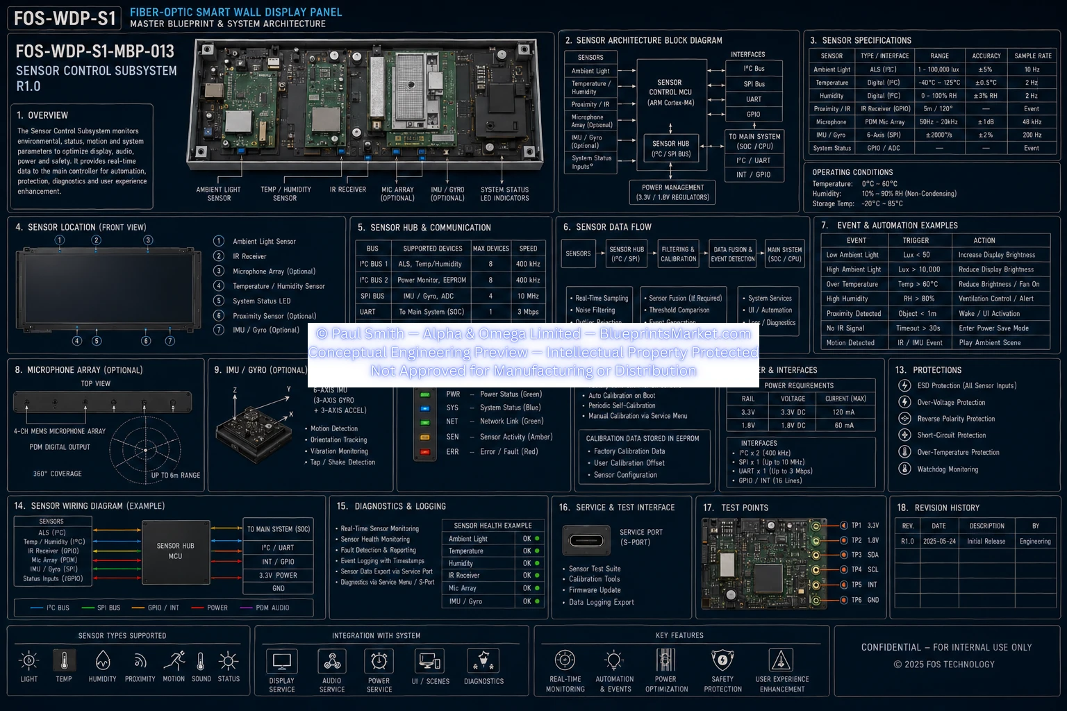
The Sensor & Control Subsystem monitors environmental, system, and user‑interaction parameters to enable automation, safety, diagnostics, and intelligent power management. It provides real‑time sensing, adaptive control, and seamless integration with display, audio, and automation services.
- Real‑time environmental sensing
- Intelligent automation and event response
- Power optimization and safety protection
- Integration with display and audio services
- Factory and user calibration support
Sensor Architecture Block Diagram
Sensors
- Ambient Light
- Temperature / Humidity
- Proximity
- Microphone Array (optional)
- IMU / Gyro (optional)
- System Status LED Indicators
Control Components
- Sensor Control MCU: ARM Cortex‑M4
- Sensor Hub: I²C / SPI Bus
- Interfaces: I²C, SPI, UART
- Main System Interface: I²C / UART / GPIO
- Power Management: 3.3V / 1.8V regulation
Sensor Specifications
| Sensor Type | Interface | Range | Accuracy | Sample Rate |
|---|---|---|---|---|
| Ambient Light | ALS (I²C) | 0–100,000 lux | ±0.5% | 20 Hz |
| Temperature | I²C | −40°C–85°C | ±0.3°C | 10 Hz |
| Humidity | I²C | 0–100% RH | ±2% | 10 Hz |
| Proximity | I²C | 0–200 mm | ±1 mm | 50 Hz |
| Microphone Array | PDM | 20 Hz–20 kHz | ±1 dB | 200 Hz |
| IMU / Gyro | SPI | ±2–16 g | ±2% | Event‑based |
Operating Conditions
- Temperature: 0°C–60°C
- Humidity: 10%–90% RH (non‑condensing)
- Storage: −10°C–85°C
Sensor Location (Front View)
- Ambient Light Sensor
- IR Receiver
- Microphone Array (optional)
- Temperature / Humidity Sensor
- System Status LED
- IMU / Gyro (optional)
Sensor Hub & Communication
| Bus | Supported Devices | Max Devices | Speed |
|---|---|---|---|
| I²C | ALS, Temp/Humidity | 8 | 400 kHz |
| SPI | IMU, Memory, EEPROM | 4 | 1 Mbps |
| UART | Main System (SoC) | 1 | 3 Mbps |
| GPIO / INT | Proximity, Status | 16 | — |
Sensor Data Flow
- Sensors → Sensor Hub (I²C / SPI)
- Filtering & Calibration
- Data Fusion & Event Detection
- Main System (SoC / CPU)
Processing Stages
- Real‑time sampling
- Noise filtering
- Outlier rejection
- Sensor fusion
- Threshold comparison
- Event generation
- System services / automation / diagnostics
Event & Automation Examples
| Event | Trigger | Action |
|---|---|---|
| Ambient Light | ALS | Increase display brightness |
| Low Ambient Light | ALS | Reduce display brightness |
| High Humidity | Humidity | Activate dehumidifier |
| Proximity Detected | Proximity | Wake display / alert |
| No IR Signal | IR Receiver | Enter power‑save mode |
| Motion Detected | IMU / Gyro | Play ambient scene |
Microphone Array (Optional)
- 4‑channel MEMS microphone array
- PDM digital output
- 360° coverage
- Up to 6 m range
IMU / Gyro (Optional)
- 6‑axis IMU (gyro + accelerometer)
- Motion detection
- Orientation tracking
- Vibration monitoring
- Tap / shake detection
System Status Indicators
| Indicator | Function | Color |
|---|---|---|
| PWR | Power status | Green |
| NET | Network link | Green |
| SYS | System status | Blue |
| ERR | Error / fault | Red |
Sensor Calibration
- Factory calibration
- Auto calibration on boot
- Manual calibration via service port
- Calibration data stored in EEPROM
- User offset support
- Configuration accessible via service menu
Power & Interfaces
| Rail | Voltage | Current (Max) |
|---|---|---|
| 3.3V | 3.3V DC | 120 mA |
| 1.8V | 1.8V DC | 60 mA |
Interfaces
- I²C / SPI / UART / GPIO
- PDM Audio
- Service Port (SPort)
- GPIO INT (16 lines)
Protections
- ESD protection
- Over‑voltage protection
- Reverse polarity protection
- Short‑circuit protection
- Over‑temperature protection
- Watchdog monitoring
Sensor Wiring Diagram (Example)
- Sensors → Sensor Hub MCU via I²C / SPI / GPIO / INT
- Power rails: 3.3V and 1.8V regulated
- Communication lines: I²C, SPI, UART
- Interrupt lines: GPIO INT (16)
Diagnostics & Logging
- Real‑time sensor monitoring
- Event detection monitoring
- Sensor health check
- Diagnostics export via service port
- Sensor data API / service menu
Service & Test Interface
- Service Port (SPort)
- Sensor validation test suites
- Sensor health reporting
- Data logging export
Test Points
- Voltage Rails: 3.3V, 1.8V
- Communication Lines: I²C, SPI, UART, GPIO
Revision History
| Rev. | Date | Description | By |
|---|---|---|---|
| R1.0 | 2025 | Initial Release | Engineering |
System Integration
- Supported Sensors: Light, Temperature, Humidity, Proximity, Motion, Sound, Status
Integration Services
- Display Service
- Audio Service
- Automation Service
Key Features
- Real‑time monitoring
- Automation and event generation
- Power optimization
- Safety protection
- Enhanced user experience
Blueprint Access & Licensing
MBP‑013 — Sensor & Control Subsystem is part of the complete multi‑volume engineering blueprint package for the FOS‑WDP‑S1 Fiber‑Optic Smart Wall Display Panel.
Contact Blueprints Market for licensing, integration support or enterprise‑level deployment.
© Paul Smith — Alpha & Omega Limited — BlueprintsMarket.com — Conceptual Engineering Preview — Not Approved for Manufacturing