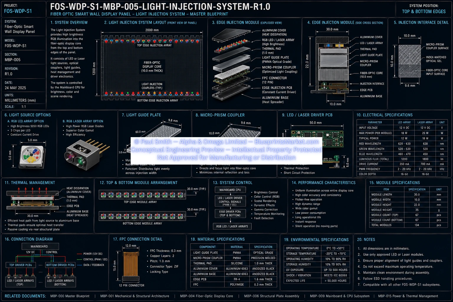
FOS‑WDP‑S1 — Light Injection System
MBP‑005 — Master Blueprint Package
Fiber‑Optic Smart Wall Display Panel
System Overview
The Light Injection System generates and couples light into the Fiber‑Optic Display Core of the FOS‑WDP‑S1 Smart Wall Display Panel. High‑brightness RGB LED arrays or RGB laser arrays mounted along the top and bottom edges inject controlled illumination into the micro‑fibre optical matrix.
The system is fully CPU‑controlled through constant‑current driver circuits, enabling precise brightness regulation, colour mixing, scene rendering, and dynamic lighting effects.
- Uniform full‑width light injection
- High optical efficiency
- Accurate RGB colour reproduction
- Stable brightness control
- Low thermal distortion
- Long operational life
- Modular serviceability
- Passive cooling
Design Objectives
- Uniform light injection
- High optical efficiency
- Accurate RGB colour reproduction
- Stable brightness and colour control
- Low thermal distortion
- Long‑term reliability
- Modular replaceability
- Efficient passive cooling
Global Dimensions
- Panel Width: 2000 mm
- Panel Height: 1200 mm
- Top Injection Module Length: 2000 mm
- Bottom Injection Module Length: 2000 mm
- Module Height: 20 mm
- Module Depth: 15 mm
- Number of Rails: 2 (top and bottom)
System Architecture
- Top RGB injection module
- Bottom RGB injection module
- RGB LED or RGB laser arrays
- Optical coupling interface
- Constant‑current driver circuits
- Flexible Printed Circuit (FPC) interconnections
- Thermal management assembly
- CPU‑controlled illumination system
Light Source Options
Option A — RGB LED Arrays
- High‑brightness surface‑mount LEDs
- Linear edge‑mounted array
- High reliability
- Long service life
- Excellent colour control
- Lower cost and maintenance
Option B — RGB Laser Arrays
- Solid‑state RGB laser modules
- Linear edge‑mounted array
- Higher optical intensity
- Narrow spectral output
- Excellent colour saturation
- Greater optical efficiency
- Enhanced long‑distance propagation
Optical Coupling System
- Material: Optical‑grade PMMA
- Method: Precision‑machined optical interface
- Function: Transfers light into the micro‑fibre matrix with minimal loss
- Alignment Tolerance: ±0.10 mm
Driver Electronics
- Driver Type: Constant‑current driver ICs
- Location: Main Electronics Bay
- Control: CPU‑controlled
- Brightness: PWM + current regulation
- Colour Mixing: Independent RGB channels
Protection Features
- Over‑current protection
- Short‑circuit protection
- Thermal monitoring
- Open‑load detection
Electrical Specifications
- Input Voltage: 12 V DC
- Driver Supply Voltage: 12 V DC
- Logic Voltage: 3.3 V DC
- Communication: PWM, GPIO
- Power Consumption: Brightness‑dependent
Thermal Management
- Cooling Method: Passive conduction
- Components: Aluminium heatsinks, thermal pads
- Heat Path: Light source → heatsink → thermal pad → rear structural plate → ambient air
Flexible Printed Circuit (FPC)
- Material: Polyimide
- Conductors: High‑current copper traces
- Connections: Mainboard, driver ICs, injection modules
- Routing: Integrated frame cable channels
- Minimum Bend Radius: 5 mm
Light Control System
- Brightness: Automatic, manual, adaptive
- Colour Control: Independent RGB channels
- Scene Rendering: CPU + firmware controlled
- Dynamic ambient lighting profiles supported
Internal Signal Path
- CPU → Driver ICs → PWM → Current Regulation → RGB Light Source → Optical Coupler → Display Core → Viewer
Optical Performance
- Uniform illumination
- Minimal leakage
- Low attenuation
- High colour uniformity
- Stable brightness
- Wide dynamic range
- Low flicker
- High optical efficiency
Environmental Specifications
- Operating Temp: 0°C to 50°C
- Storage Temp: −20°C to 70°C
- Humidity: 10%–90% RH
- UV Resistance: High
- Service Life: > 50,000 hours
Mechanical Specifications
- Housing: Extruded aluminium
- Finish: Black anodised
- Mounting: Precision alignment brackets
- Fasteners: Stainless steel
- Alignment: Factory calibrated
- Service Access: Rear electronics compartment
Manufacturing Sequence
- Manufacture aluminium housings
- Install RGB LED or laser arrays
- Install driver PCBs
- Fit heatsinks
- Apply thermal pads
- Install optical couplers
- Mount modules to display core
- Connect FPC assemblies
- Connect driver circuits
- Verify optical alignment
- Perform thermal testing
- Test illumination uniformity
- Complete electrical testing
- Final QA
Quality Assurance
- Optical alignment
- Colour uniformity
- Brightness uniformity
- Electrical continuity
- Driver communication
- Thermal performance
- Mechanical alignment
- Coupling efficiency
Serviceability
Serviceable Components
- RGB LED/Laser modules
- Driver PCBs
- Flexible Printed Circuits
- Thermal pads
- Heatsinks
- Mounting brackets
Non‑Serviceable Components
- Factory‑machined optical couplers
- Integrated optical alignment features
Material Specification
| Component | Material |
|---|---|
| Module Housing | Extruded Aluminium |
| Heatsinks | Aluminium |
| Thermal Pads | Silicone TIM |
| Optical Couplers | Optical‑Grade PMMA |
| FPC | Polyimide + Copper |
| Fasteners | Stainless Steel |
Performance Characteristics
- High optical coupling efficiency
- Uniform full‑width injection
- Stable RGB output
- High brightness
- Low flicker
- Passive thermal stability
- Long‑term reliability
- Modular serviceability
System Integration
- MBP‑004 — Fiber‑Optic Display Core
- MBP‑006 — Intermediate Structural Plate
- MBP‑007 — Rear Structural Back Plate
- MBP‑009 — Mainboard & CPU Subsystem
- MBP‑010 — Power Supply Subsystem
- MBP‑015 — Power & Thermal Management
- MBP‑018 — Firmware & Software Architecture
Design Requirements
- Controlled RGB illumination
- Precise optical alignment
- Efficient light coupling
- Stable colour and brightness
- Effective passive cooling
- Reliable communication with mainboard
- Easy maintenance of replaceable components
- Compatibility with all related subsystems
Blueprint Access & Licensing
MBP‑005 — Light Injection System is part of the complete multi‑volume engineering blueprint package for the FOS‑WDP‑S1 Fiber‑Optic Smart Wall Display Panel.
Contact Blueprints Market for licensing, integration support or enterprise‑level deployment.