FOS‑WDP‑S1 — Capacitive Touch Subsystem
MBP‑003 — Master Blueprint Package
Fiber‑Optic Smart Wall Display Panel
System Overview
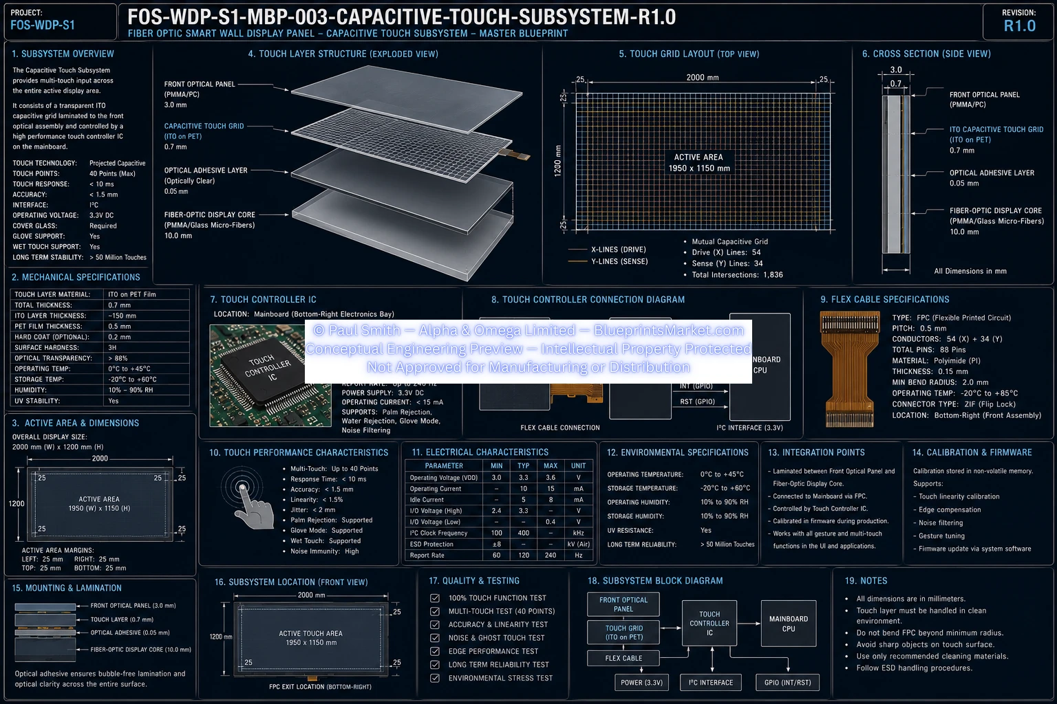
The Capacitive Touch Subsystem provides the primary human‑machine interface (HMI) for the FOS‑WDP‑S1 Fiber‑Optic Smart Wall Display Panel. A transparent projected capacitive sensing layer is laminated directly beneath the front optical panel, enabling multi‑touch input, gesture detection, and precise finger tracking while maintaining maximum optical clarity.
The subsystem communicates with the Mainboard CPU through a dedicated touch controller using an I²C interface, ensuring fast response, low latency, and seamless integration with the display core.
- Projected capacitive multi‑touch
- High optical transparency
- Fast response and low latency
- Long operational life
- Minimal electromagnetic interference
- Full integration with mainboard and firmware
Design Objectives
- Accurate multi‑touch sensing
- High transparency for optical clarity
- Low power consumption
- Durable long‑life construction
- Reliable operation under varying conditions
- Minimal EMI and noise interference
- Seamless integration with display core
Global Dimensions
- Panel Width: 2000 mm
- Panel Height: 1200 mm
- Touch Active Area: 1990 × 1190 mm
- Inactive Border: 5 mm perimeter
- Touch Layer Thickness: 0.7 mm
- Total Coverage: Entire front viewing surface
Touch Layer Construction
Capacitive Touch Film
- Material: ITO deposited on PET
- Thickness: 0.7 mm
- High optical transmission
- Flexible transparent conductive film
- Function: Detects capacitive changes from finger proximity
Electrode Matrix
- Type: Projected Capacitive (P‑Cap)
- Grid: Mutual capacitance X‑Y matrix
- Material: Transparent ITO
- Pitch: ~5 mm
- Scanning: Sequential row/column scanning
- Controller: Dedicated touch controller IC
Front Optical Integration
The touch layer is laminated directly beneath the front optical panel using optically clear adhesive.
- Layer 1 — Front Optical Panel (3.0 mm)
- Layer 2 — Optically Clear Adhesive (OCA)
- Layer 3 — ITO Touch Film (0.7 mm)
- Layer 4 — Optically Clear Adhesive (OCA)
- Layer 5 — Fiber‑Optic Display Core (10.0 mm)
This construction minimizes internal reflections and maintains optical clarity.
Touch Controller Subsystem
- Location: Mainboard Electronics Bay
- Interface: I²C
- Voltage: 3.3 V DC
Functions
- Capacitive sensing
- Noise filtering
- Coordinate calculation
- Gesture recognition
- Multi‑touch processing
- Palm rejection
- Self‑calibration
Output Data
- Touch coordinates
- Pressure approximation
- Gesture events
- Touch count
- Diagnostic status
Flexible Printed Circuit (FPC)
- Type: Flexible Printed Circuit
- Location: Bottom edge of touch panel
- Connections: ITO Matrix → Controller → Mainboard
- Construction: Copper traces on polyimide
- Routing: Internal cable channel
- Minimum Bend Radius: 5 mm
Electrical Specifications
- Supply Voltage: 3.3 V DC
- Power Consumption: < 500 mW
- Communication: I²C
- Touch Scan Rate: 120 Hz minimum
- Max Touch Points: 10
- Latency: < 10 ms
Touch Performance
- Single & multi‑touch
- Swipe, pinch, zoom, rotate
- Long press, double tap, drag
- Accuracy: ±1.0 mm
- Edge Accuracy: ±2.0 mm
- Minimum Detectable Object: 5 mm
Firmware Interface
The touch controller communicates with the Mainboard CPU through the Touch HAL.
- Touch Sensor Matrix → Controller IC → I²C → HAL → OS → Applications
Functions
- Coordinate processing
- Gesture recognition
- Touch event buffering
- Interrupt generation
- Calibration routines
Environmental Specifications
- Operating Temp: 0°C to 50°C
- Storage Temp: -20°C to 70°C
- Humidity: 10%–90% RH
- Condensation: Not permitted
- UV Resistance: High
- Service Life: > 50,000 hours
EMI & Noise Control
- Ground reference plane
- ITO edge grounding
- Filtered controller inputs
- Digital filtering
- Adaptive sensitivity
- EMI suppression
- ESD protection
Power Management
- Supply Rail: 3.3 V DC
- Sleep Mode: Supported
- Wake Sources: Touch detection, system wake
- Modes: Active, Standby, Sleep
Calibration
Factory Calibration
- Sensor baseline
- Coordinate mapping
- Edge alignment
- Noise profile
- Sensitivity adjustment
Self‑Test
- Startup diagnostics
- Open/short circuit detection
- Sensor integrity verification
Internal Wiring
- Touch Layer → FPC → Controller → Mainboard → CPU → OS
- Routing inside perimeter frame cable channels
- Isolated from audio and power wiring
Mechanical Mounting
- Optically bonded assembly
- No mechanical fasteners
- Alignment via optical alignment pins
- Adhesive: Optically Clear Adhesive (OCA)
- Assembly Tolerance: ±0.20 mm
Manufacturing Sequence
- Manufacture ITO touch film
- Inspect electrode matrix
- Apply first OCA layer
- Bond touch film to optical panel
- Apply second OCA layer
- Bond assembly to display core
- Install FPC
- Connect touch controller
- Route FPC through frame channels
- Connect to mainboard
- Optical inspection
- Touch calibration
- Multi‑touch verification
- Electrical testing
- Final QA
Quality Assurance
- Optical transparency
- Touch sensitivity
- Coordinate accuracy
- Gesture recognition
- Controller communication
- Electrical continuity
- Environmental performance
- Calibration verification
Serviceability
The touch subsystem is a laminated assembly.
Serviceable Components
- Flexible Printed Circuit
- Touch Controller
- Mainboard Interface
Non‑Serviceable Components
- ITO Touch Film
- Optical Adhesive Layers
- Laminated Touch Assembly
Material Specification
| Component | Material |
|---|---|
| Touch Film | PET |
| Conductive Layer | Indium Tin Oxide (ITO) |
| Adhesive | Optically Clear Adhesive (OCA) |
| FPC | Polyimide with Copper Traces |
| Connector | Board‑to‑Board Locking Connector |
Design Requirements
- High optical transparency
- Uniform touch sensitivity
- Reliable multi‑touch detection
- Low latency
- Stable indoor operation
- EMI resistance
- Dimensional and electrical stability
- Full integration with MBP‑002, MBP‑004, MBP‑009, MBP‑018
Blueprint Access & Licensing
MBP‑003 — Capacitive Touch Subsystem is part of the complete multi‑volume engineering blueprint package for the FOS‑WDP‑S1 Fiber‑Optic Smart Wall Display Panel.
Contact Blueprints Market for licensing, integration support or enterprise‑level deployment.