FOS‑WDP‑S1 — Assembly & Construction Sequence
MBP‑017 — Master Blueprint Package
Fiber‑Optic Smart Wall Display Panel
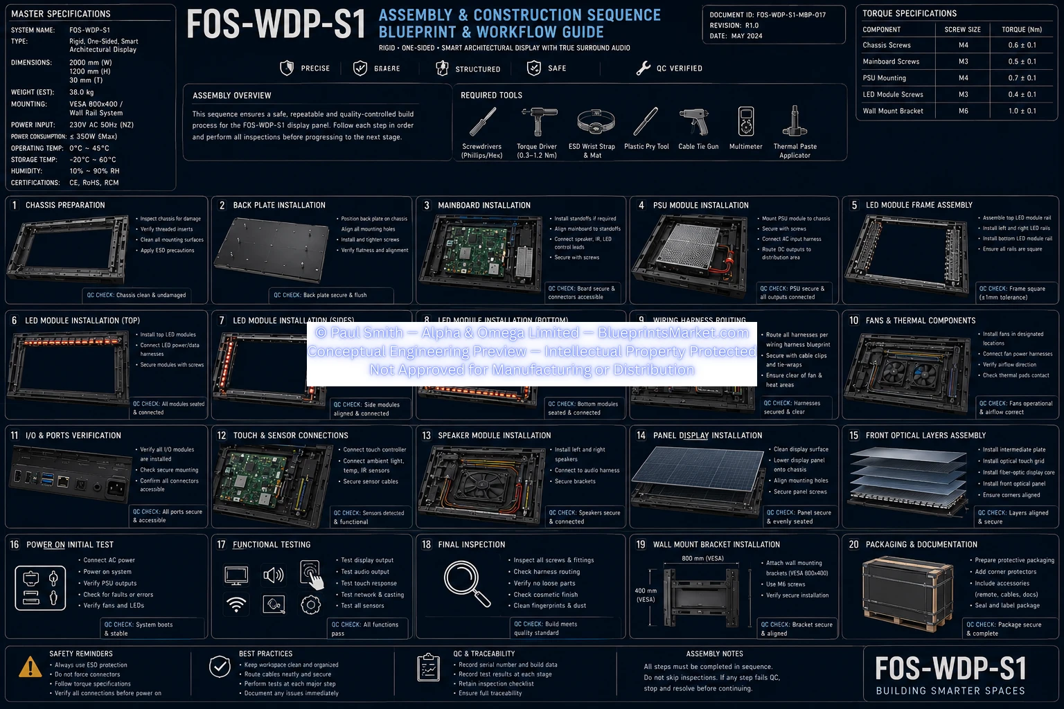
Master Specifications
| Parameter | Specification |
|---|---|
| System Name | FOS‑WDP‑S1 |
| Type | Rigid, One‑Sided Smart Architectural Display |
| Dimensions | 1200 mm (H) × 2000 mm (W) × 100 mm (D) |
| Weight (Est.) | 35 kg |
| Mounting | VESA 800×400 / Wall & Stand Support |
| Power Input | 230V AC, 50Hz (NZ) |
| Power Consumption | ≤ 350W (Max) |
| Storage Temperature | −20°C to 60°C |
| Humidity | 10% to 90% RH |
| Certifications | CE, RoHS, RCM |
Assembly Overview
This sequence defines the complete, quality‑controlled build process for the FOS‑WDP‑S1 display panel. Each step must be followed in order, with mandatory QC CHECK verification before progressing.
Required Tools
- Philips Screwdrivers
- Hex Screwdrivers
- Torque Driver (0.3–1.2 Nm)
- ESD Wrist Strap & ESD Mat
- Plastic Pry Tool
- Cable Tie Gun
- Multimeter
- Thermal Paste Applicator
Torque Specifications
| Component | Screw Size | Torque (Nm) |
|---|---|---|
| Chassis Screws | M4 | 0.6 ± 0.1 |
| Mainboard Screws | M3 | 0.5 ± 0.1 |
| PSU Mounting | M4 | 0.7 ± 0.1 |
| LED Module Screws | M3 | 0.4 ± 0.1 |
| Wall Mount Bracket | M6 | 1.0 ± 0.1 |
Assembly Sequence (Steps 1–20)
Step 1 — Chassis Preparation
- Inspect chassis for damage
- Apply full ESD protection
QC CHECK: Chassis integrity confirmed
Step 2 — Back Plate Installation
- Position rear structural back plate
- Secure using M4 screws
QC CHECK: Torque verified
Step 3 — Mainboard Installation
- Mount mainboard in electronics bay
- Connect mainboard harnesses
QC CHECK: All connectors latched
Step 4 — PSU Module Installation
- Mount PSU module
- Connect AC and DC outputs
QC CHECK: AC polarity verified
Step 5 — LED Module Frame Assembly
- Assemble LED module frame
QC CHECK: Frame alignment confirmed
Step 6 — LED Module Installation (Top)
- Install top LED modules
QC CHECK: LED harness continuity
Step 7 — LED Module Installation (Sides)
- Install left and right LED modules
QC CHECK: Edge alignment verified
Step 8 — LED Module Installation (Bottom)
- Install bottom LED modules
QC CHECK: Full LED ring continuity
Step 9 — Wiring Harness Routing
- Route harnesses along chassis edges
- Secure with clips and ties
QC CHECK: Bend radius ≥ 25 mm
Step 10 — Fans & Thermal Components
- Install PWM fans
- Apply thermal paste to heat pads
QC CHECK: Fan spin test
Step 11 — I/O & Ports Verification
- Verify HDMI, USB, Ethernet, Audio ports
QC CHECK: Port alignment confirmed
Step 12 — Touch & Sensor Connections
- Connect touch controller and sensors
QC CHECK: Touch reset line verified
Step 13 — Speaker Module Installation
- Install left, center, right speaker modules
QC CHECK: Speaker impedance test
Step 14 — Panel Display Installation
- Mount fiber‑optic display panel
QC CHECK: No flex or pressure points
Step 15 — Front Optical Layers Assembly
- Install optical PMMA layer
- Install capacitive touch layer
QC CHECK: Surface cleanliness verified
Step 16 — Power On Initial Test
- Connect AC power
- Verify system boot
QC CHECK: PSU power‑good signal
Step 17 — Functional Testing
- Test display
- Test audio
- Test sensors
- Test wireless
QC CHECK: All subsystems pass
Step 18 — Final Inspection
- Inspect screws
- Inspect harnesses
- Inspect cleanliness
QC CHECK: Full visual inspection
Step 19 — Wall Mount Bracket Installation
- Install VESA 800 mm bracket
QC CHECK: Torque 1.0 Nm
Step 20 — Packaging & Documentation
- Apply protective packaging
- Include documentation and serial number
QC CHECK: Packaging integrity
Safety Reminders
- Always use ESD protection
- Inspect all components before assembly
- Verify all connections before applying power
- Maintain clean workspace
Best Practices
- Keep assembly area organized
- Record serial numbers and build data
- Maintain full traceability for QA
- Follow torque specifications precisely
Document Information
| Field | Value |
|---|---|
| Document ID | FOSWDPS1MBP017 |
| Revision | R1.0 |
| Date | May 2024 |
| Title | Assembly & Construction Sequence |
| Tagline | Building Smarter Spaces |
Blueprint Access & Licensing
MBP‑017 — Assembly & Construction Sequence is part of the complete multi‑volume engineering blueprint package for the FOS‑WDP‑S1 Fiber‑Optic Smart Wall Display Panel.
Contact Blueprints Market for licensing, integration support or enterprise‑level deployment.