
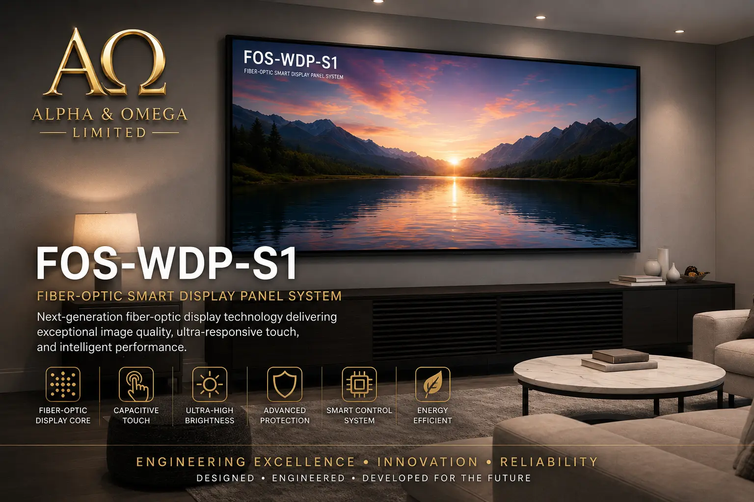
FOS‑WDP‑S1 — Internal Wiring Harness
MBP‑016a — Master Blueprint Package
Fiber‑Optic Smart Wall Display Panel
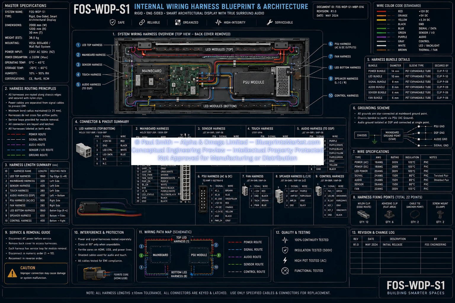
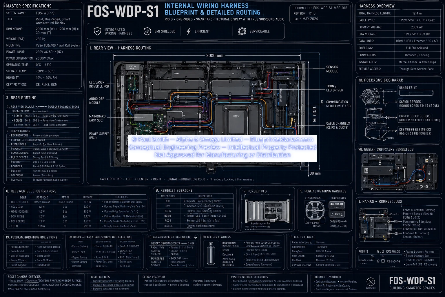
Master Specifications
| Parameter | Specification |
|---|---|
| System Name | FOS‑WDP‑S1 |
| Type | Rigid, One‑Sided Smart Architectural Display |
| Dimensions | 1200 mm × 700 mm × 30 mm |
| Weight (Est.) | 12.8 kg |
| Mounting | VESA 400×400 / Wall Mount |
| Power Input | 230V AC, 50Hz (NZ) |
| Power Consumption | ≤ 350W (Max) |
| Operating Temperature | 0°C – 40°C |
| Storage Temperature | −10°C – 60°C |
| Humidity | 20% – 80% RH |
Harness Routing Principles
- All harnesses routed along chassis edges
- Power cables separated from signal cables
- Minimum bend radius ≥ 25 mm
- Service loops for module removal
- All connectors keyed and latched
- Harnesses labeled at both ends
Routing Categories
- POWER ROUTE
- SIGNAL / I/O ROUTE
- AUDIO ROUTE
- GROUND ROUTE
Harness Length Summary
| No | Harness Name | Length (mm) | Routing Path |
|---|---|---|---|
| 1 | LED Top Harness | 1360 | Left Side |
| 2 | Mainboard Harness | 320 | Left Side |
| 3 | Sensor Harness | 180 | Left Side |
| 4 | Touch Harness | 260 | Left Side |
| 5 | Audio Harness (to DSP) | 400 | Bottom Right |
| 6 | PSU Harness | 480 | Bottom Right |
| 7 | Fan Harness | 300 | Bottom Right |
| 8 | Speaker Harness (L/C/R) | 540 | Bottom Right |
| 9 | Control Harness | 400 | Bottom Right |
Connector & Pinout Summary
LED Harness
- Signal: White
- +12V DC: Red
- LED Data: Blue
Mainboard Harness
Pins include PSU_12V, FAN_CTRL, LED_SYNC, AUDIO_OUT_L/R, SENSOR_IN, TOUCH_RST, etc.
Sensor Harness
- Signal: Yellow
- +5V DC: Red
- GND: Black
Touch Harness
- Signal: Yellow
- +5V DC: Red
- Reset: White
- GND: Black
Audio Harness (DSP)
- L_OUT: White
- R_OUT: Red
- GND: Black
PSU Harness
- AC_L: Brown
- AC_N: Blue
- DC_12V: Red
- DC_GND: Black
Fan Harness
- +12V DC: Red
- Signal: Yellow
- GND: Black
Speaker Harness
- L_OUT: White
- C_OUT: Blue
- R_OUT: Red
- GND: Black
Control Harness
- Signal: Yellow
- +5V DC: Red
- GND: Black
Wire Color Code (Standard)
| Color | Function |
|---|---|
| Red | +12V DC |
| Orange | +5V DC |
| Yellow | Signal |
| Blue | Audio / Data |
| Green | Sync / Control |
| White | Reset / Backlight |
| Gray | Ground |
| Brown | Thermal / Fan |
Grounding Scheme
- All grounds star‑connected at mainboard ground point
- Chassis bonded to PSU AC ground
- Audio shield grounded at DSP end only
Wire Specifications
| Type | Rating | Insulation | Notes |
|---|---|---|---|
| 22AWG | 300V | PVC | Twisted Pair |
| 24AWG | 150V | PVC | Shielded Pair |
| 26AWG | 150V | PVC | — |
Harness Fixing Points
| Type | Quantity | Location |
|---|---|---|
| Adhesive Clip | 12 | Frame interior |
| Cable Tie | 8 | Edge channels |
| Screw Mount | 2 | Rear corners |
Quality & Testing
- 100% continuity tested
- Insulation tested (500V)
- Hi‑Pot tested (AC)
- Functional tested under load
Inspection Criteria
- No pin damage
- Correct labeling
- Proper strain relief
- Verified connector latch engagement
System Wiring Harness Overview
- LED Modules (Top)
- Mainboard
- Sensor Harness
- Touch Harness
- Audio Harness (DSP)
- PSU Module
- Fan Harness
- LED Modules (Bottom)
- Speaker Harness
- Control Harness
Caution
Improper connection may cause damage or system malfunction. Always verify connector orientation and pin alignment before installation.
Revision & Change Log
| Rev | Date | Description | By |
|---|---|---|---|
| R1.0 | May 2024 | Initial Release | FOS Engineering |
Document Information
| Field | Value |
|---|---|
| Document ID | FOSWDPS1MBP016 |
| Revision | R1.0 |
| Date | May 2024 |
| Title | Internal Wiring Harness |
| System Tagline | Building Smarter Spaces |
Blueprint Access & Licensing
MBP‑016a — Internal Wiring Harness is part of the complete multi‑volume engineering blueprint package for the FOS‑WDP‑S1 Fiber‑Optic Smart Wall Display Panel.
Contact Blueprints Market for licensing, integration support or enterprise‑level deployment.
© Paul Smith — Alpha & Omega Limited — BlueprintsMarket.com — Conceptual Engineering Preview — Not Approved for Manufacturing
© Paul Smith — Alpha & Omega Limited — BlueprintsMarket.com — Conceptual Engineering Preview — Not Approved for Manufacturing