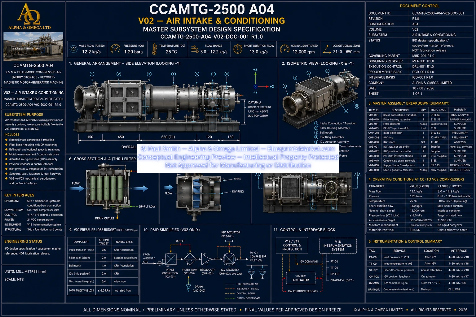
The CCAMTG-2500 A04 Air Intake & Conditioning subsystem is the engineered front end of the machine's compressed-air process architecture. It receives incoming process air, filters and conditions the flow, monitors the inlet state, manages moisture and contamination risks, and delivers a controlled low-loss airflow to the three-stage centrifugal compressor.
Designed as an integrated part of the A04 machinery platform, the V02 subsystem combines industrial air filtration, aerodynamic inlet conditioning, an engineered bellmouth, inlet guide vane control, instrumentation, drainage and compressor-interface management within one coordinated intake architecture.
The primary purpose of the intake system is to provide the compressor with a stable and controlled inlet condition while minimizing unnecessary pressure loss, airflow distortion and contamination. The system is coordinated directly with the downstream compressor and its operating strategy.
V02 is designed around the controlled compressor inlet state used by the CCAMTG-2500 A04 system architecture. The intake assembly must maintain the required airflow while keeping losses and inlet distortion within the limits established by the overall compressor and cycle-performance design.
The filtration system protects downstream compressor equipment from damaging airborne contamination while maintaining the low-pressure-loss characteristics required by a high-flow industrial intake.
The architecture uses a serviceable filter-bank approach with differential-pressure monitoring so that filter condition can be tracked during operation. The clean downstream side is isolated from uncontrolled bypass paths and is designed to remain protected during normal filter servicing.
Downstream of the filtration stage, the inlet architecture transitions the conditioned air toward the compressor through an aerodynamic bellmouth arrangement. The bellmouth is intended to reduce avoidable inlet losses and provide a suitable flow field for the compressor inlet and guide-vane assembly.
Final aerodynamic contouring is determined through the detailed engineering and CFD development process contained within the controlled engineering package rather than being represented as fabrication-ready geometry on the public website.
The CCAMTG-2500 A04 incorporates an actuated inlet guide vane assembly ahead of the compressor. The IGV system provides controlled regulation of compressor inlet flow and pre-swirl as required by the compressor operating strategy.
Air-intake control is integrated with the wider compressor protection architecture. The IGV system operates as part of the compressor flow-management strategy, while fast anti-surge protection remains a separate coordinated protective function.
This separation of operating control and rapid protective response is important to maintaining compressor operability across changing flow conditions and system operating modes.
Pressure loss through an industrial intake directly affects downstream compressor and overall system performance. V02 therefore treats intake pressure loss as a controlled engineering parameter across filtration, inlet transitions, guide vanes and any required acoustic treatment.
V02 is designed not simply to move air into the machine, but to deliver an inlet flow condition suitable for the high-speed compressor. Airflow uniformity, distortion, swirl, pressure loss and guide-vane behaviour are therefore coordinated with the compressor aerodynamic design.
Moisture management is incorporated into the intake architecture so that geometry-created low points can be drained through controlled routes rather than allowing condensate to accumulate within the incoming-air system.
The air intake is instrumented to provide the operating and diagnostic information required by the CCAMTG-2500 A04 control architecture. These measurements support compressor performance calculations, filter-condition monitoring, airflow verification and automated system supervision.
The V02 material architecture is based around corrosion-resistant industrial construction suitable for the intake environment, with final material selections coordinated to structural strength, corrosion resistance, manufacturability, aerodynamic performance and operating conditions.
Where required by the installation environment, the intake architecture can incorporate engineered acoustic treatment or an inlet silencer. Acoustic equipment is not treated as an arbitrary fixed component: its requirement and geometry depend on the compressor inlet spectrum, acceptable sound levels and site-specific acoustic analysis.
V02 interfaces directly with the CCAMTG-2500 A04 PLC, safety and system-control architecture. Intake instrumentation and IGV feedback provide operating information to the control system while commanded guide-vane positioning supports controlled compressor operation.
Air Intake & Conditioning operates as part of the complete CCAMTG-2500 A04 system rather than as an isolated intake assembly. Its aerodynamic, mechanical, structural and controls interfaces are coordinated across multiple engineering volumes.
The controlled engineering program includes verification of the intake subsystem's geometry, cleanliness, filter integrity, guide-vane operation, instrumentation, airflow path and pressure-loss performance before final system acceptance.
The licensed CCAMTG-2500 A04 engineering package expands the V02 subsystem into its controlled engineering documentation, drawings and supporting design records. These materials cover the intake architecture at substantially greater technical depth than the public website presentation.
Detailed CFD-defined geometry, filter sizing calculations, pressure-loss calculations, final guide-vane geometry, supplier-specific selections, controlled tolerances, joint schedules, fabrication requirements, inspection criteria and other implementation-level engineering information remain within the licensed package and its controlled development process.
The CCAMTG-2500 A04 Air Intake & Conditioning system establishes the airflow quality entering the machine's compression architecture. By integrating filtration, aerodynamic conditioning, inlet guide vane control, moisture management, instrumentation and compressor-interface coordination, V02 provides the controlled process-air entry point for the complete A04 system.
V02 is a controlled A04 subsystem design specification and master engineering reference. It establishes the current Air Intake & Conditioning architecture without representing unresolved CFD, acoustic, supplier, structural or site-specific parameters as finalized fabrication data.
Final manufacturing and construction-level implementation requires closure of the applicable engineering analyses, supplier selections, hazard reviews, site conditions and controlled design-release requirements identified by the complete CCAMTG-2500 A04 engineering package.