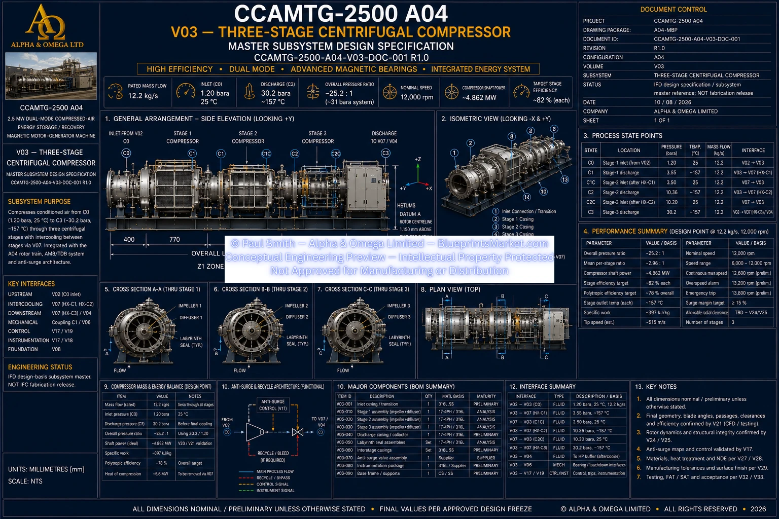
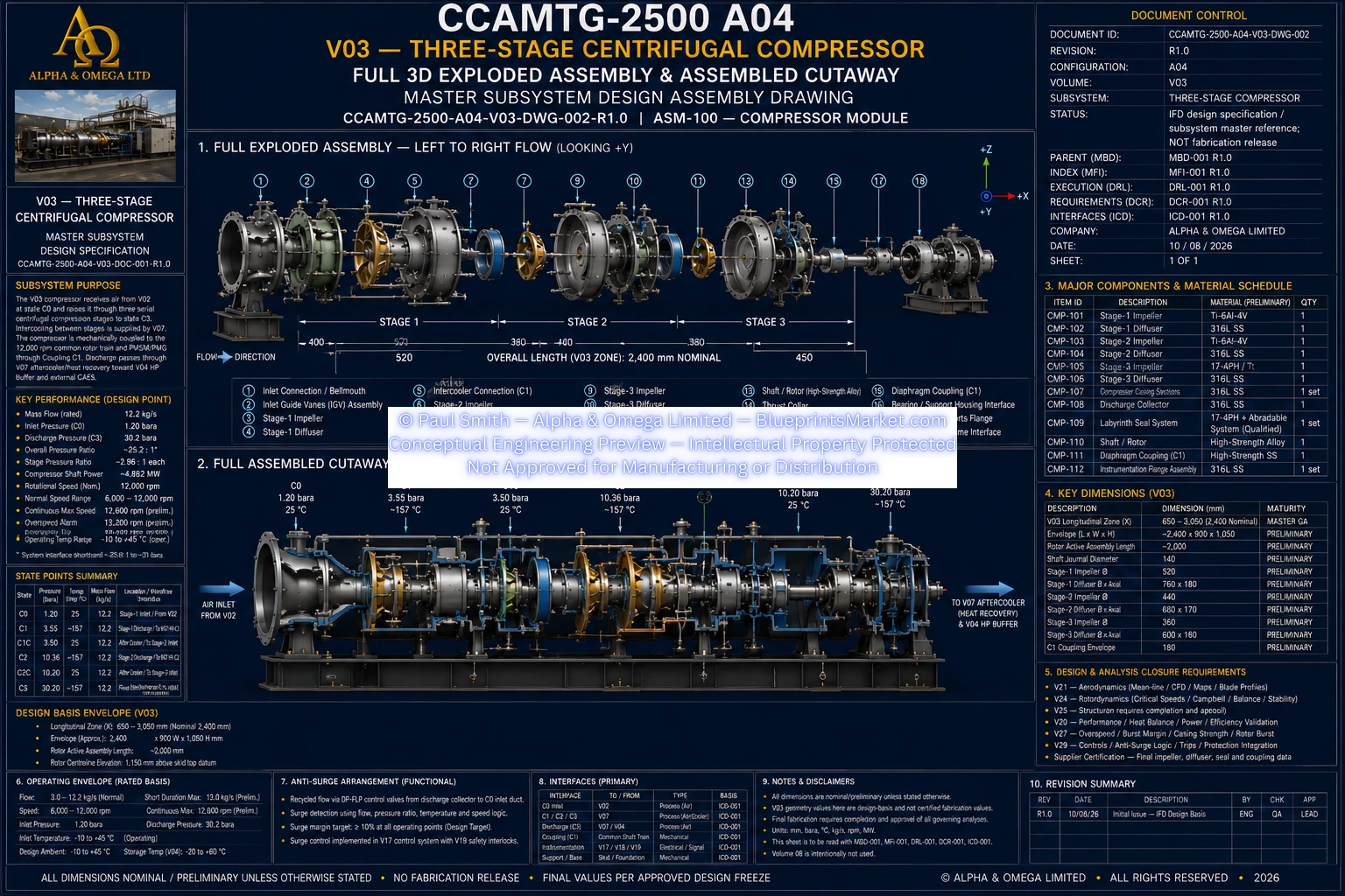
The CCAMTG-2500 A04 Three-Stage Centrifugal Compressor is the primary charge-mode rotating process subsystem within the A04 compressed-air energy storage and recovery platform. It receives conditioned air from the upstream intake system and raises pressure through three serial centrifugal compression stages before delivering the compressed air toward thermal recovery, the high-pressure buffer vessel, and external compressed-air storage.
The compressor is mechanically integrated with the common high-speed rotor train and bidirectional permanent-magnet motor-generator. Its architecture combines staged compression, intercooling interfaces, aerodynamic flow management, anti-surge protection, high-speed rotor integration, instrumentation, and pressure-controlled downstream delivery in one coordinated subsystem.
V03 uses three centrifugal compression stages arranged in series. Each stage raises the process-air pressure before the flow is cooled and conditioned for the next compression stage. This staged architecture reduces thermal loading and supports the wider thermal-energy-recovery strategy used throughout the CCAMTG-2500 A04 system.
The first compressor stage receives conditioned process air from the V02 Air Intake & Conditioning subsystem. The incoming airflow is delivered through the engineered inlet architecture and then accelerated through the first centrifugal impeller and diffuser stage.
At the master design point, Stage 1 raises the air from approximately 1.20 bara to approximately 3.55 bara before the flow is routed to the first intercooling stage.
After first-stage intercooling, the process air returns to the compressor at a reduced temperature and enters the second centrifugal compression stage. The second stage continues the pressure rise while preserving the controlled serial mass-flow architecture of the A04 system.
The second stage raises the process pressure to approximately 10.36 bara at the master mean-line design point before the air is routed through the second intercooling stage.
The third stage receives the second-stage flow after intercooling and performs the final pressure rise required by the high-pressure compressed-air architecture.
At the controlled design point, Stage 3 discharges at approximately 30.2 bara before downstream aftercooling, thermal-energy capture, buffering, and storage integration.
Compression raises process-air temperature significantly, so the CCAMTG-2500 A04 architecture uses staged intercooling between compressor stages. The cooling system returns the air toward the controlled next-stage inlet condition while transferring recoverable thermal energy into the wider A04 thermal-energy system.
The compressor is mechanically coupled into the CCAMTG-2500 A04 common rotor train. The compressor, permanent-magnet motor-generator, and turbine operate around the same high-speed mechanical architecture when coupled.
Each compressor stage combines a centrifugal impeller with a diffuser and internal flow-routing architecture. The impeller adds kinetic energy to the airflow, while the diffuser and downstream passages recover pressure and guide the process air toward the next thermal or compression stage.
Final blade profiles, diffuser throats, return-channel geometry, shaft fits and other fabrication-critical dimensions are controlled engineering outputs and remain inside the licensed engineering package and its analysis process.
Compressor surge can produce unstable flow and damaging pressure oscillations, so the V03 architecture includes a dedicated anti-surge recycle system designed to protect the compressor across transient and off-design conditions.
The compressor casing provides the structural and pressure-containing envelope around the rotating stages and internal flow passages. The current A04 material basis uses corrosion-resistant stainless construction and high-speed non-contact sealing concepts suitable for the process-air path.
V03 integrates process and machinery instrumentation so compressor performance, thermal condition, rotor health, anti-surge operation, and interstage conditions can be monitored by the wider CCAMTG-2500 A04 control system.
The compressor rotor operates as part of the A04 active magnetic bearing system rather than relying solely on conventional contact-bearing support during normal high-speed operation. Magnetic bearing control, rotor-position sensing, vibration monitoring, and touchdown protection are coordinated with the compressor's dynamic requirements.
The compressor uses a combination of high-strength rotating materials and corrosion-resistant stationary materials selected for high-speed mechanical duty, fatigue resistance, pressure containment, aerodynamic performance, and manufacturability.
Compressor operation is coordinated with the wider CCAMTG-2500 A04 control system. Before high-speed rotation, magnetic-bearing levitation, cooling, control power and required operating permissives must be established.
The compressor is one of the most highly integrated subsystems in the complete CCAMTG-2500 A04 architecture. Its mechanical, aerodynamic, thermal, structural, electrical, controls and safety interfaces are coordinated across multiple engineering volumes.
The controlled engineering program includes performance and protection verification for the three-stage compressor before final acceptance. Testing is intended to confirm that the compressor operates consistently with its approved aerodynamic and mechanical design basis.
The licensed CCAMTG-2500 A04 engineering package contains the detailed V03 compressor documentation and blueprint material required to study the subsystem beyond this public overview.
Detailed impeller and diffuser geometry, controlled stage dimensions, rotor and shaft interfaces, casing design, labyrinth seal details, anti-surge engineering, critical tolerance registers, manufacturing information, calculations, inspection requirements, and other implementation-level engineering data remain within the licensed package.
Within the complete CCAMTG-2500 A04 architecture, the three-stage centrifugal compressor performs the principal energy-storage charging function. Electrical energy supplied to the motor-generator is converted into mechanical shaft power, which drives the compressor and raises process-air pressure for downstream storage.
The subsystem therefore forms a critical link between electrical charging, compressed-air storage, thermal-energy recovery, and later turbine-based electrical generation.
V03 is a controlled A04 compressor subsystem master and establishes a physically consistent real-world engineering basis for the three-stage centrifugal compressor.
It is not represented as an IFC fabrication release. Final impeller aerodynamics, diffuser geometry, rotor dimensions, pressure-boundary details, seal clearances, anti-surge valve sizing, transient behaviour and high-speed structural details remain subject to the required CFD, FEA, rotor-dynamic, thermal, transient and supplier design-freeze processes.