CCAMTG-2500 A04 — Integrated Compressed-Air Energy Storage & Turbine Generator System

The CCAMTG-2500 A04 is an advanced conceptual engineering platform developed around compressed-air energy storage, high-speed rotating machinery, thermal energy recovery, electrical power conversion, and intelligent industrial control.

The system combines a three-stage centrifugal compressor, high-pressure air buffering, thermal energy recovery, a three-stage expansion turbine, a bidirectional permanent-magnet motor-generator, active magnetic bearings, electrical power conversion, battery energy storage, structural machinery support, instrumentation, and automated control within one coordinated engineering architecture.

CCAMTG-2500 A04 is designed as a dual-mode energy storage and recovery concept. During charging, electrical energy drives the compressor system to store energy as compressed air while recoverable compression heat is transferred into the thermal system. During generation, stored compressed air is conditioned and expanded through the turbine train to drive the motor-generator and recover electrical power.

CCAMTG-2500 A04 — Key System Targets

Dual-Mode Compressed-Air Energy Storage Architecture

CCAMTG-2500 A04 is designed around two coordinated operating modes: electrical charging and compressed-air power recovery. The architecture allows the same high-speed rotor train and permanent-magnet electrical machine to participate in both energy storage and generation.

Charge Mode

In charge mode, electrical power is delivered through the bidirectional electrical conversion system to the permanent-magnet motor-generator. The motor drives the common high-speed rotor and three-stage centrifugal compressor, progressively increasing air pressure while thermal energy generated during compression is removed through intercooling and directed toward thermal energy recovery.

Generation Mode

In generation mode, stored compressed air is supplied through the high-pressure control architecture, thermally conditioned, and expanded through the three-stage turbine. Turbine shaft power drives the permanent-magnet machine in generator mode, allowing recovered mechanical energy to be converted into controlled electrical power.

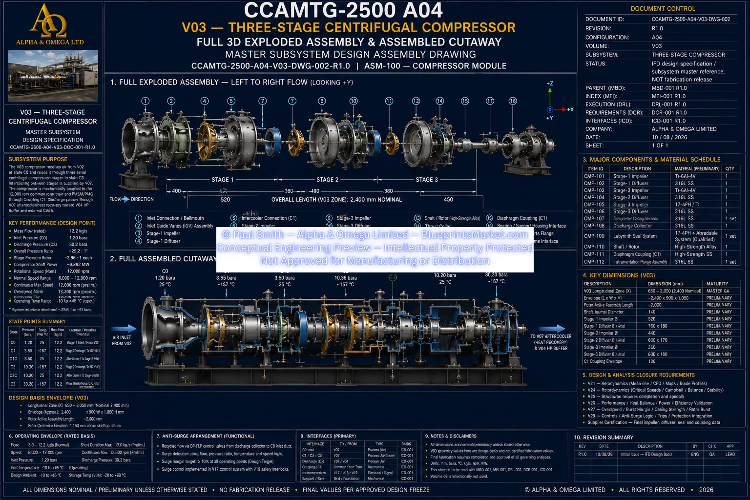
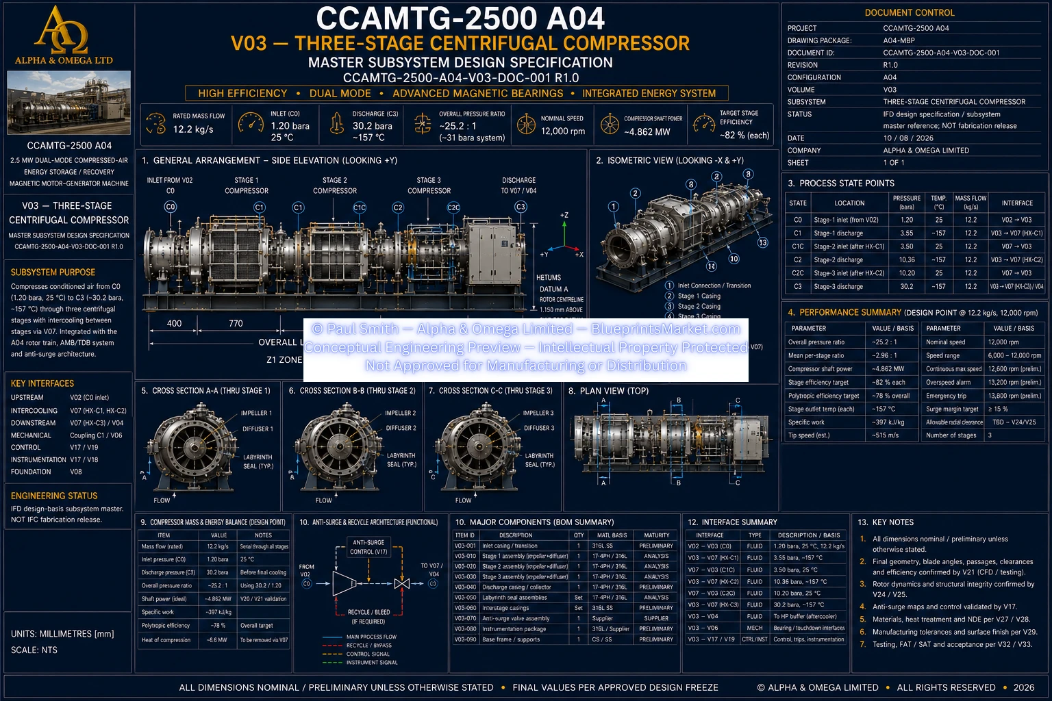
Three-Stage Centrifugal Compressor

The compression system uses three coordinated centrifugal stages designed around the common CCAMTG rotor speed and master airflow condition. Interstage cooling controls temperature between compression stages while supporting thermal energy capture for later reuse elsewhere in the energy cycle.

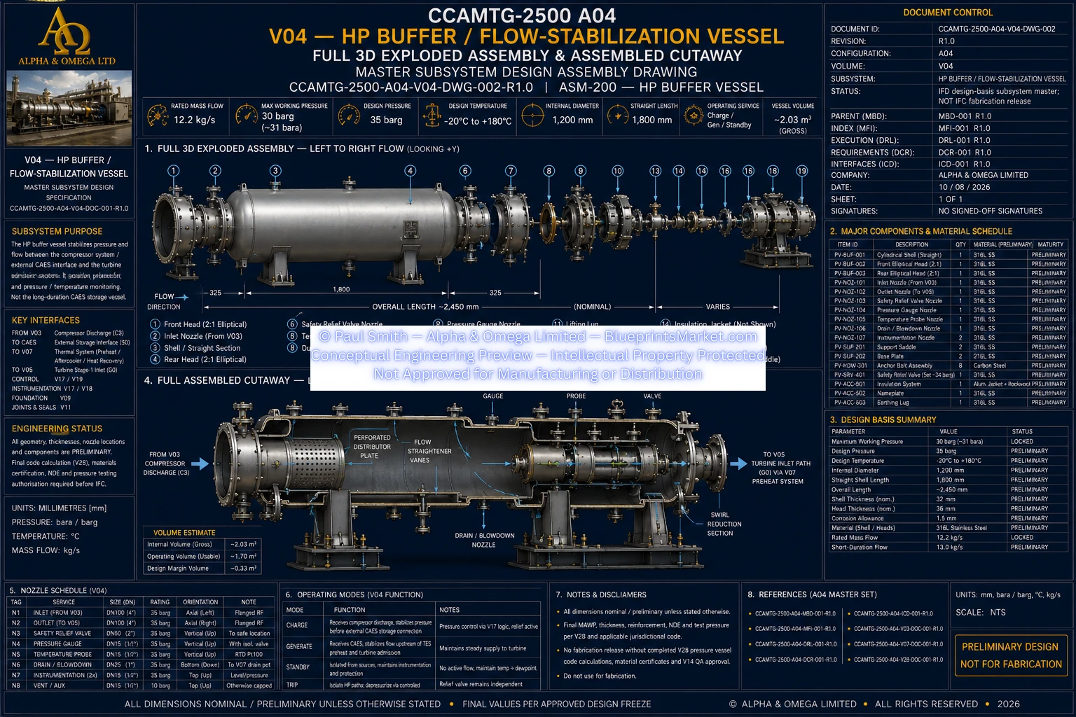
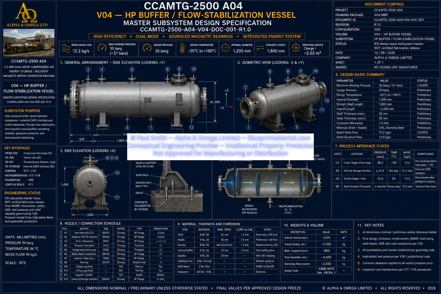
High-Pressure Buffer & Flow Stabilization

A dedicated high-pressure buffer vessel provides a controlled interface between compressed-air generation, external storage, and turbine operation. Its function is to stabilize pressure and flow, support controlled system transitions, and provide a defined high-pressure interface between major process sections.

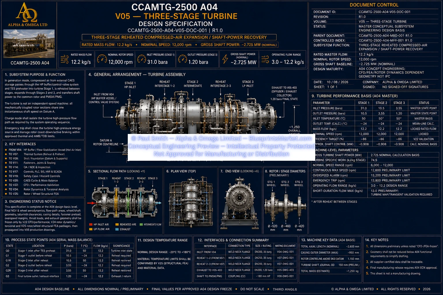
Three-Stage Turbine Power Recovery

The turbine subsystem converts the stored pressure and thermal energy of compressed air back into mechanical shaft power. Three expansion stages operate in sequence, with thermal conditioning between stages helping maintain the intended expansion cycle and improve usable energy recovery.

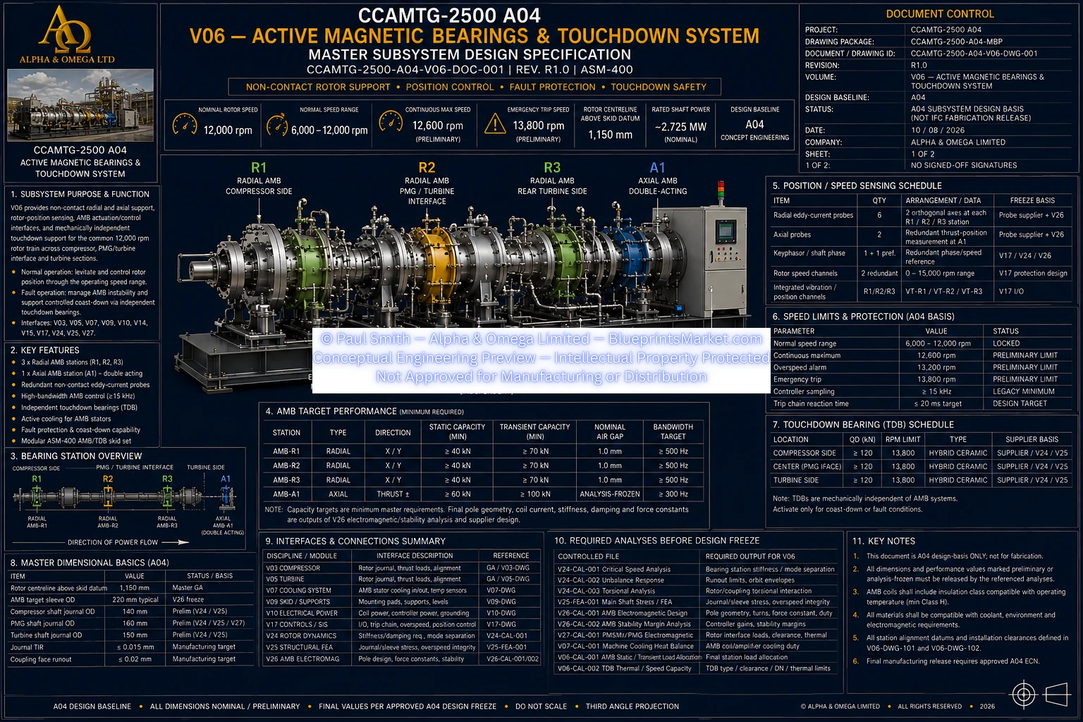
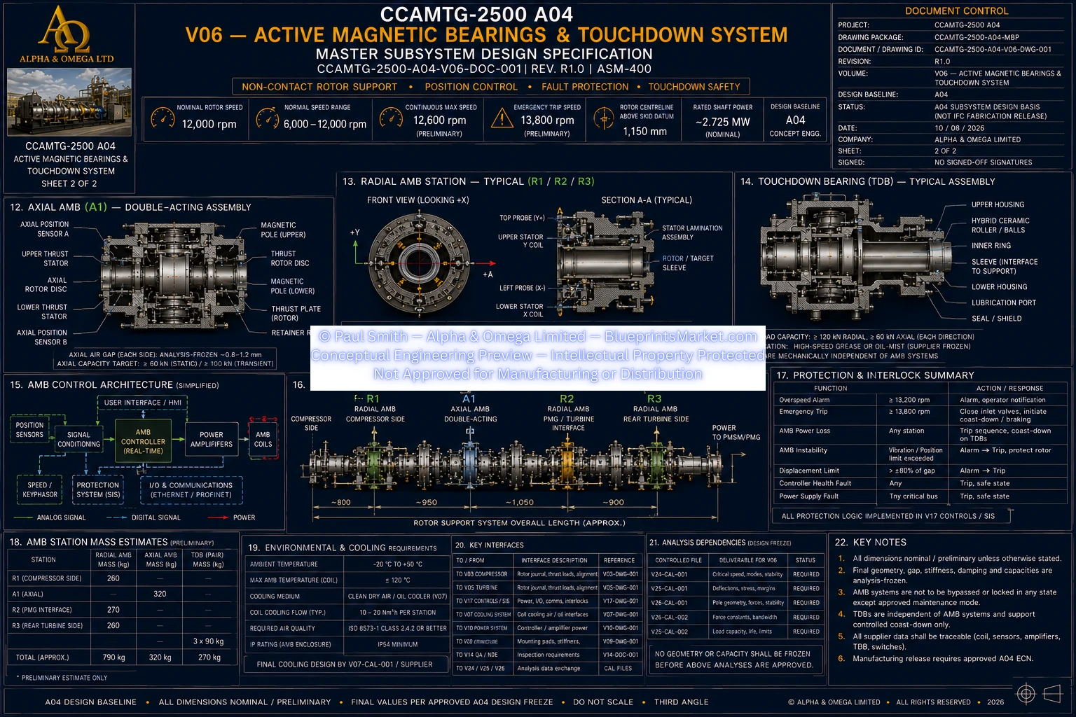
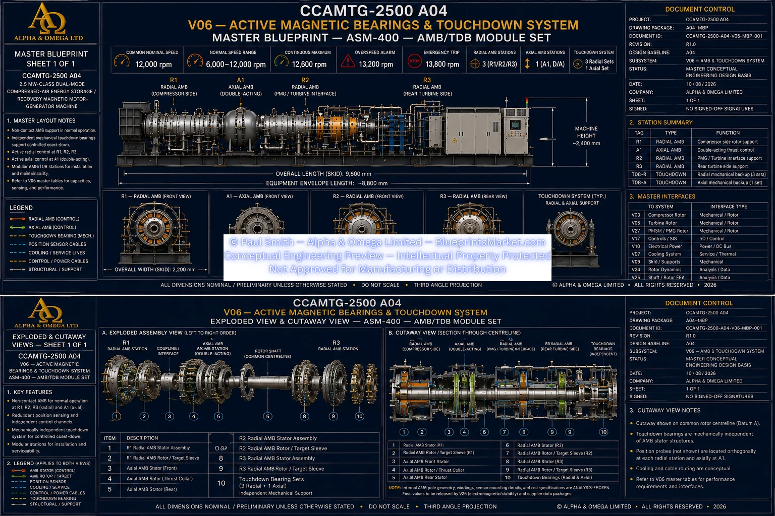
Active Magnetic Bearing Rotor System

The CCAMTG-2500 A04 rotor train is supported by an active magnetic bearing architecture designed for high-speed, low-contact operation. Magnetic bearings actively control rotor position during normal operation while independent touchdown bearing systems provide mechanical protection during defined abnormal or shutdown conditions.

Bidirectional Permanent-Magnet Motor-Generator

At the center of the CCAMTG architecture is a high-speed permanent-magnet synchronous motor-generator. The machine operates bidirectionally: as a motor during compressed-air charging and as a generator during stored-energy recovery.

Thermal Energy Recovery & Cooling

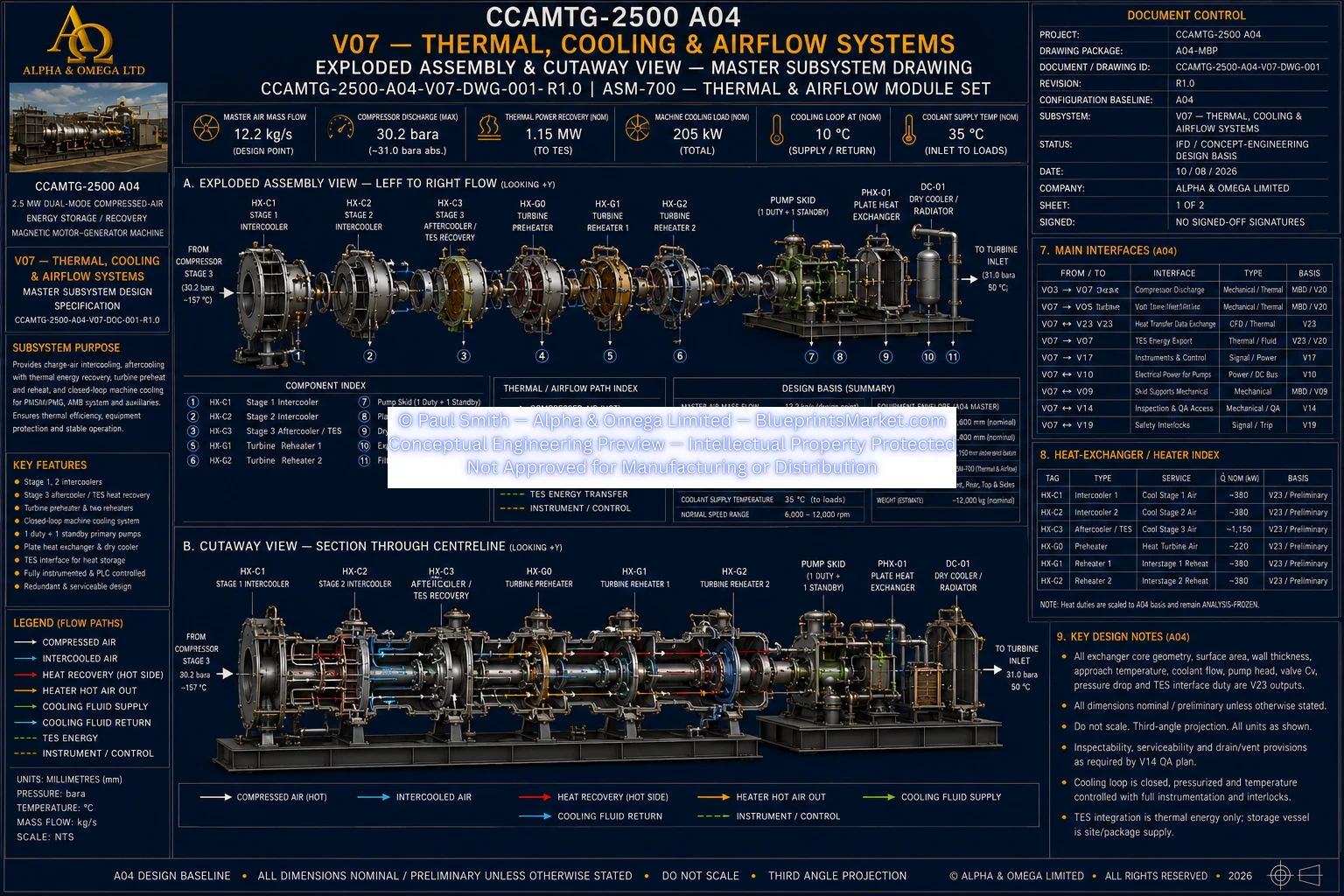
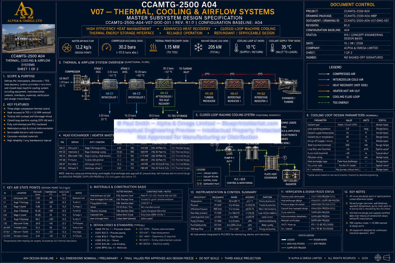
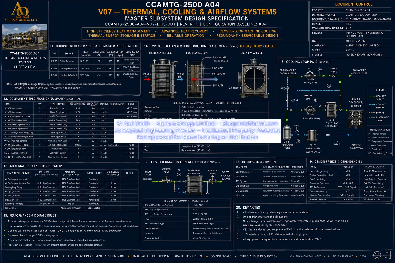
Thermal management is a major part of the CCAMTG-2500 A04 energy architecture. Heat produced during air compression is removed through staged cooling and can be transferred into a thermal energy storage system. Recovered thermal energy can then support turbine preheating and interstage reheating during generation.

Electrical Power Conversion & Energy Management

The electrical architecture connects the motor-generator, DC power system, battery energy storage, power conversion equipment, and site electrical interface. Bidirectional power electronics allow energy to move between the grid or battery system and the rotating machine according to the selected operating mode.

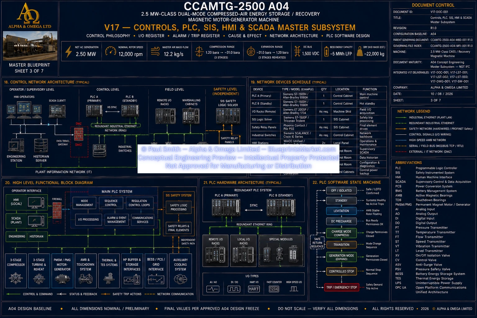
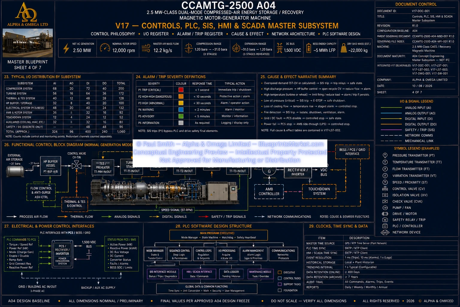
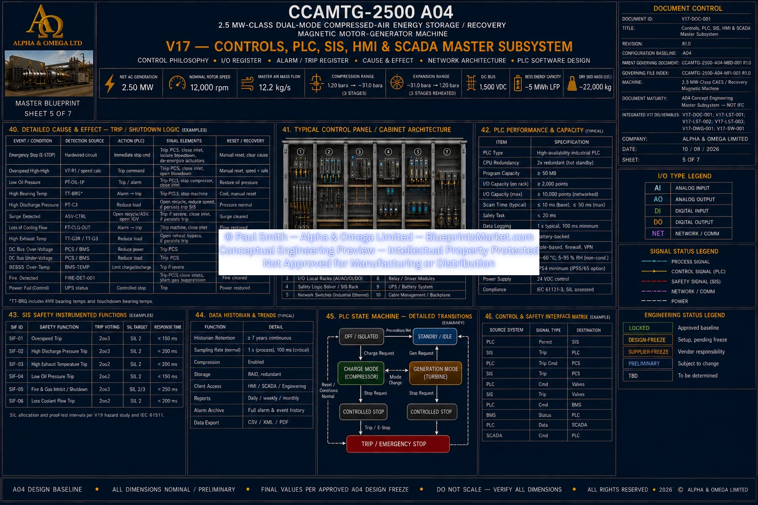
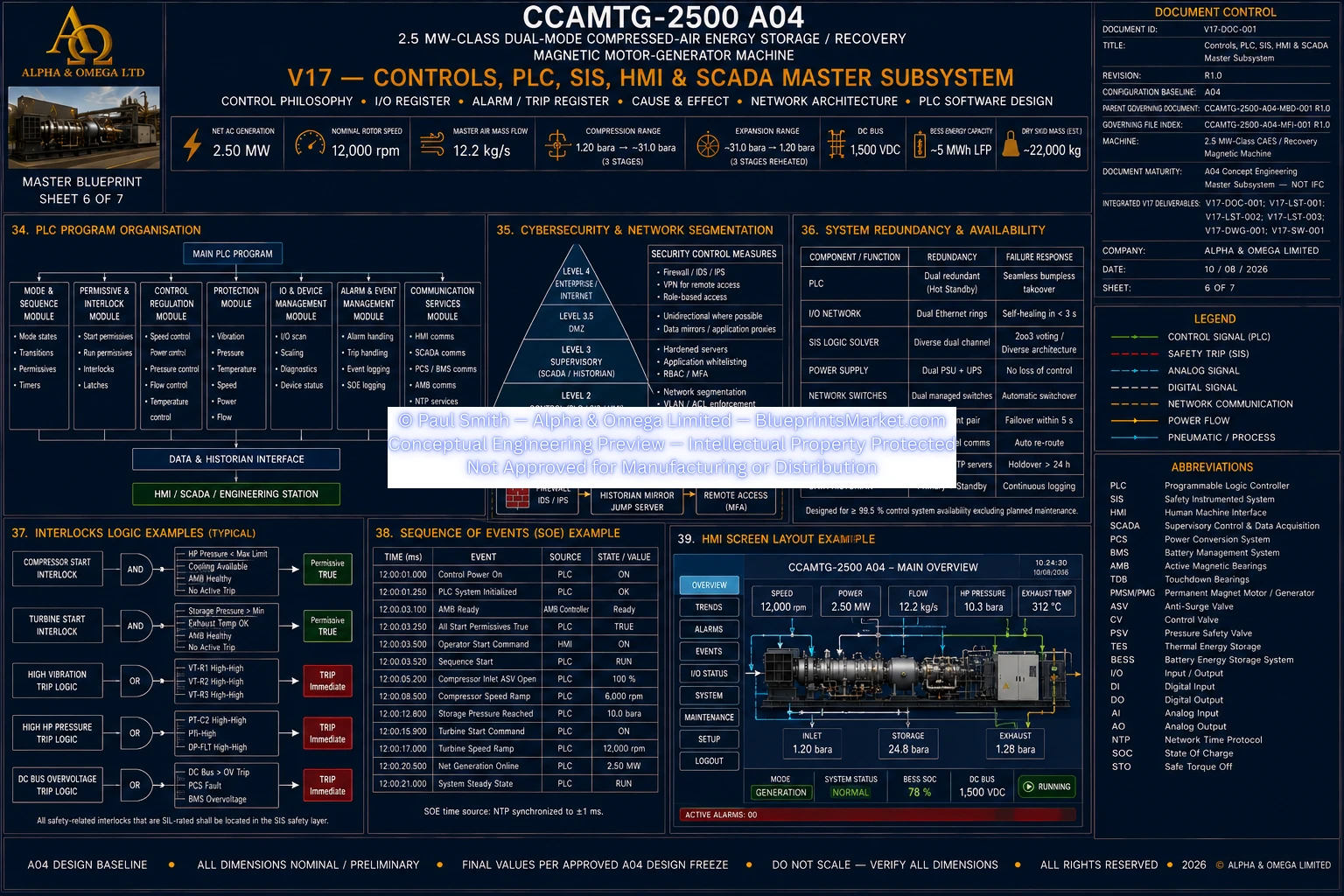
Industrial Controls, PLC, SIS, HMI & SCADA

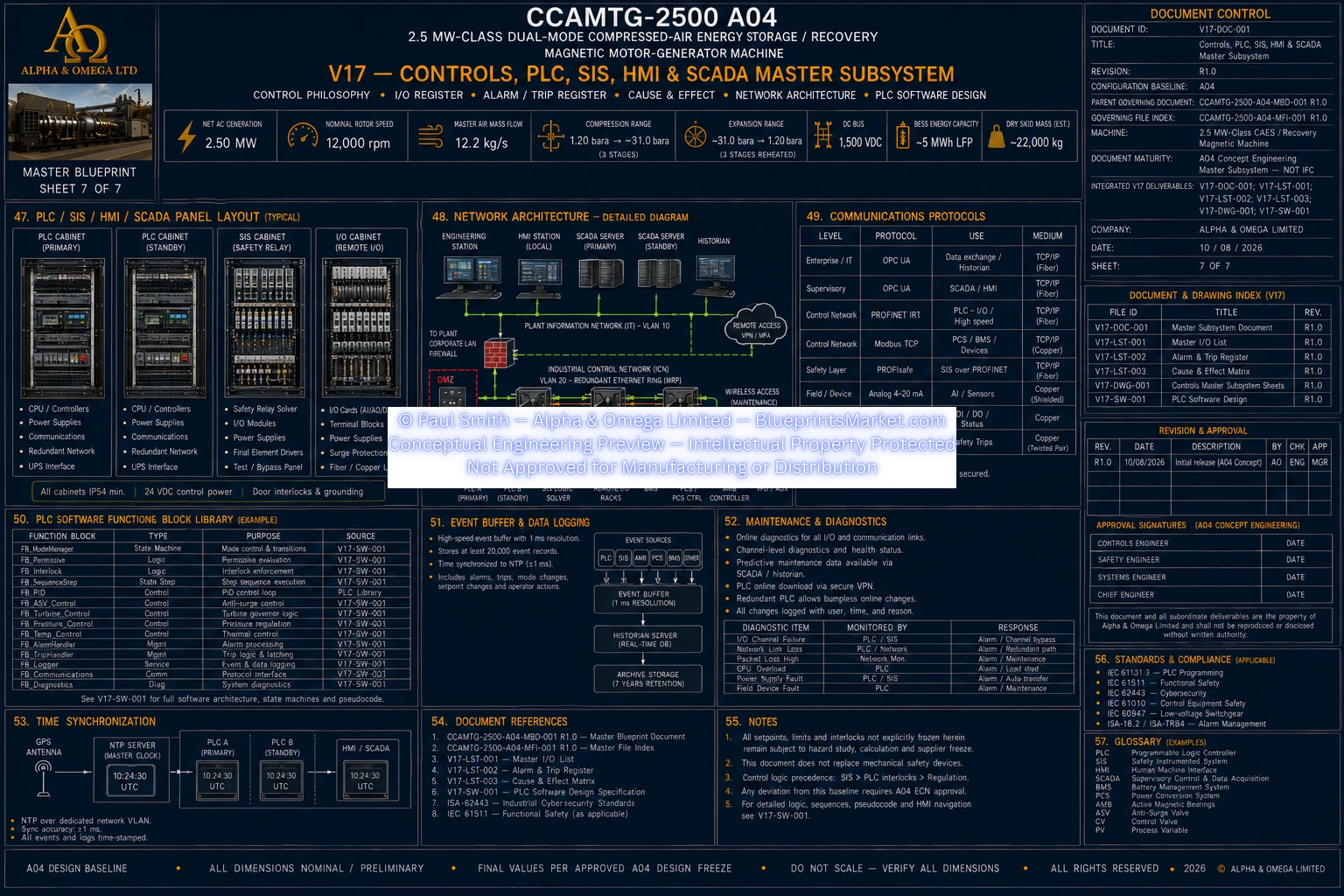
CCAMTG-2500 A04 integrates industrial automation across the compressed-air, mechanical, thermal, electrical, magnetic-bearing, and safety systems. The control architecture coordinates machine startup, charging, generation, operating transitions, controlled shutdown, alarms, interlocks, and protective responses.

Structural Skid & Integrated Machinery Platform

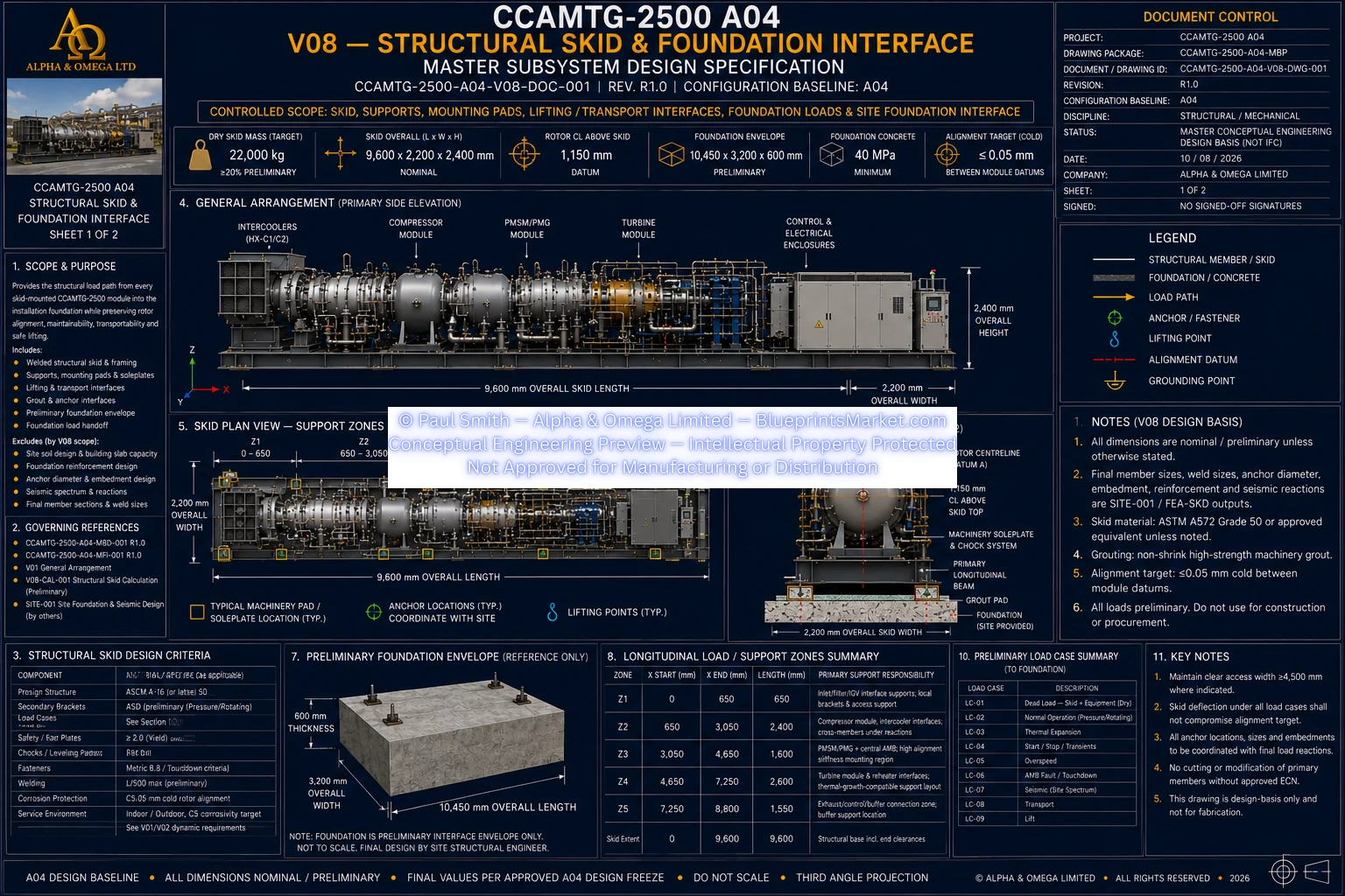
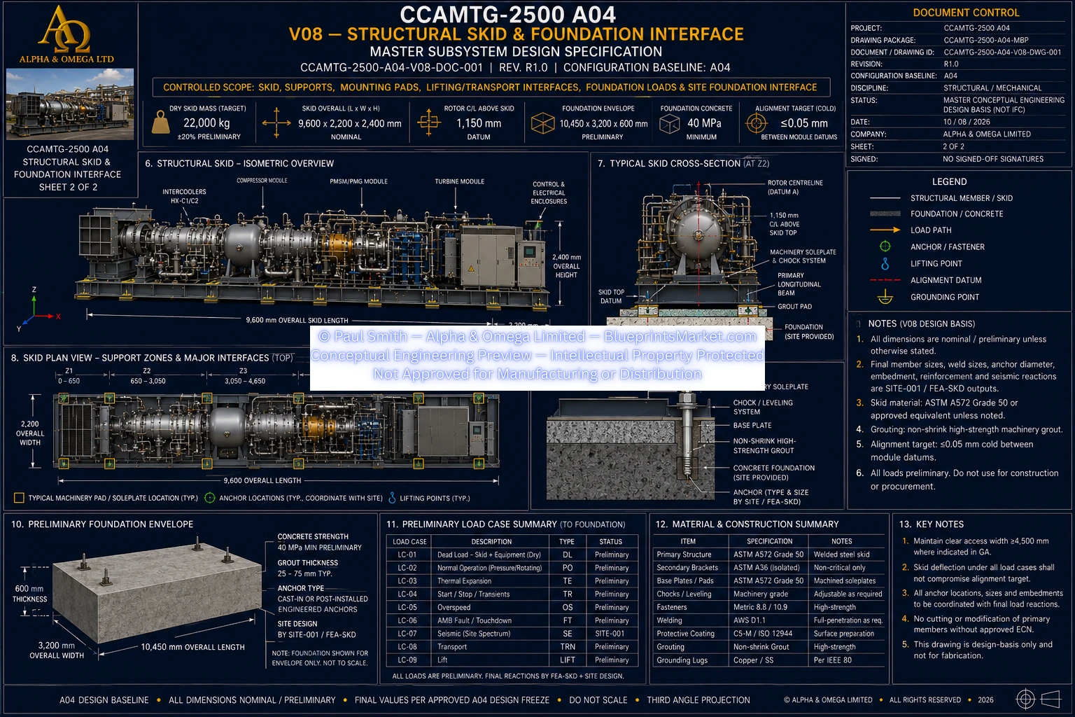
The major mechanical and electrical systems are coordinated around an industrial structural skid architecture designed to maintain machine alignment, support rotating equipment, provide service access, and establish the interface between the CCAMTG package and its installation foundation.

Integrated Safety & Protection Architecture

High-energy pressure, rotating machinery, electrical power, magnetic bearings and battery energy storage require coordinated protection. The A04 design basis incorporates independent pressure protection, fail-safe isolation, rotor monitoring, electrical protection, controlled shutdown logic and maintenance isolation principles.

CCAMTG-2500 A04 System Architecture

Integrated Engineering Package

The CCAMTG-2500 A04 blueprint package is organized as a coordinated multi-discipline conceptual engineering system rather than a single isolated drawing. Individual subsystem documentation addresses the principal mechanical, thermal, electrical, structural, controls, manufacturing, quality, installation, maintenance, commissioning, and safety disciplines required to understand the complete machine architecture.

Detailed engineering drawings, subsystem specifications, manufacturing information, internal dimensional schedules, calculations, component schedules, inspection requirements, assembly procedures, and controlled engineering data are contained within the licensed CCAMTG-2500 A04 blueprint and documentation package.

Concept Engineering Status

CCAMTG-2500 A04 is a real-world-based conceptual engineering design system developed around internally coordinated pressure, airflow, speed, power, thermal, mechanical and electrical relationships. It is not represented as a certified fabrication release or an approved production machine.

Final manufacturing, construction, certification and installation would require the applicable discipline engineering analyses, supplier-certified equipment data, aerodynamic and structural validation, rotor-dynamic and electromagnetic analysis, pressure-system certification, hazard review, site engineering, and jurisdictional approval.

Explore the CCAMTG-2500 A04 Subsystems

Explore the dedicated CCAMTG-2500 A04 subsystem pages for the compressor, turbine, magnetic bearings, thermal and cooling architecture, electrical power conversion, controls and SCADA, structural skid, high-pressure buffer vessel, system integration, manufacturing engineering, QA and inspection, assembly, maintenance, commissioning, and safety architecture.
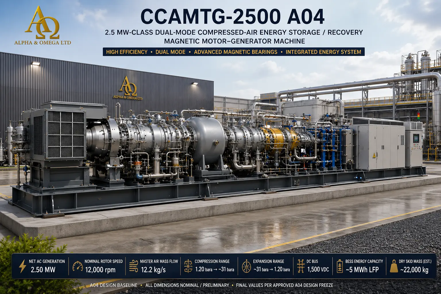
CCAMTG-2500 A04 — Official Master Cover Renders

CCAMTG-2500 A04 Official Master Cover 3D Render
© Paul Smith — Alpha & Omega Limited — PlatformClouds.com — Conceptual Engineering Preview — Not Approved for Manufacturing
CCAMTG-2500 A04 Official Master Cover Render
© Paul Smith — Alpha & Omega Limited — PlatformClouds.com — Conceptual Engineering Preview — Not Approved for Manufacturing

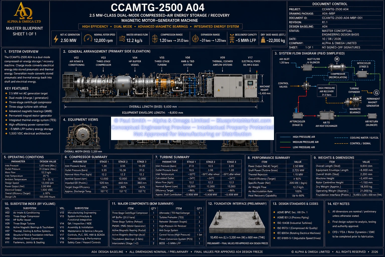
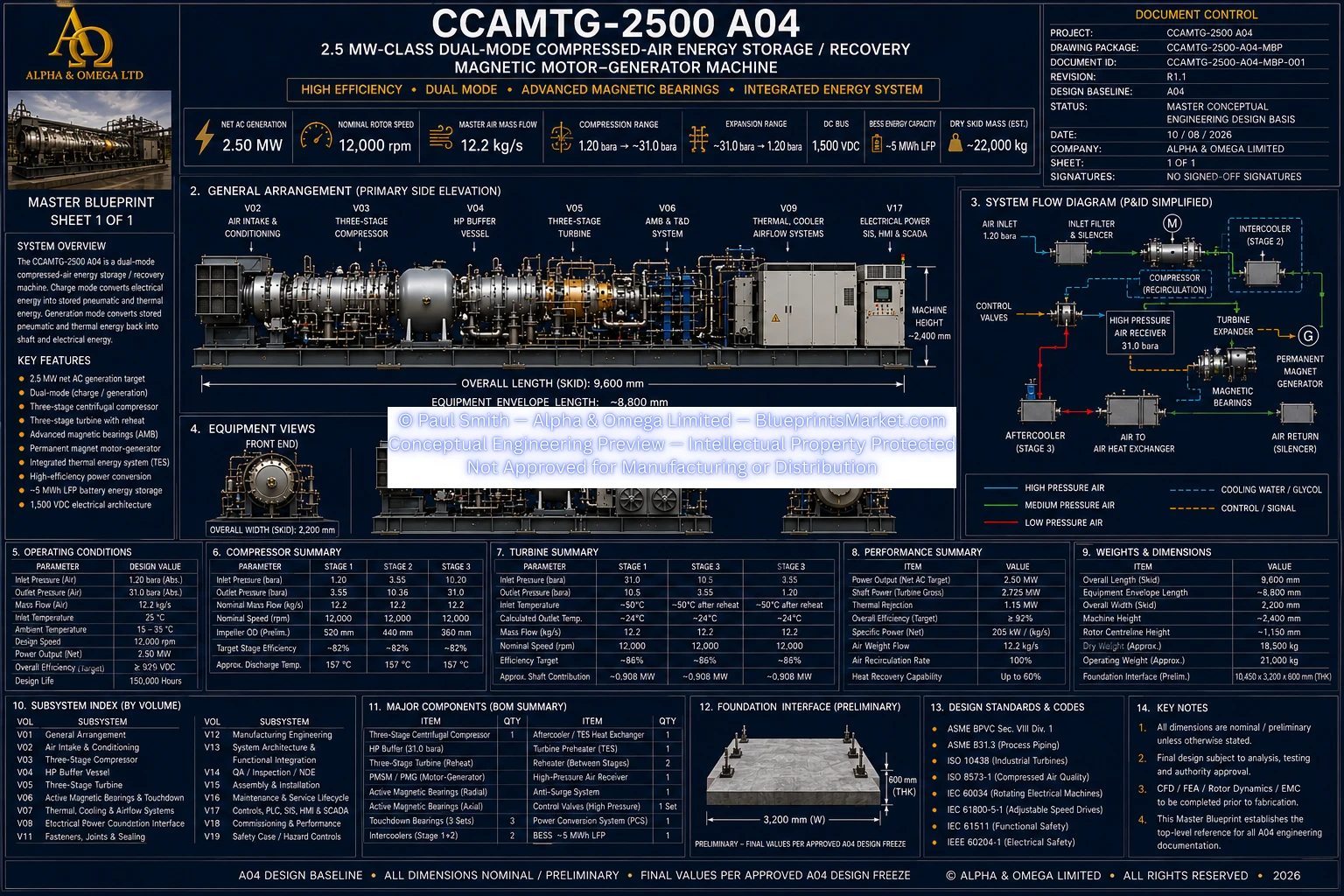
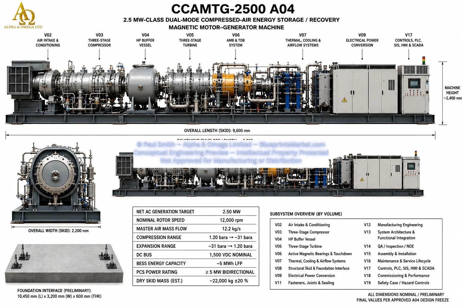
CCAMTG-2500 A04 — Master Blueprint

CCAMTG-2500 A04 Master Blueprint R1.1
© Paul Smith — Alpha & Omega Limited — PlatformClouds.com — Conceptual Engineering Preview — Not Approved for Manufacturing
CCAMTG-2500 A04 Master Blueprint Sheet 1 of 1
© Paul Smith — Alpha & Omega Limited — PlatformClouds.com — Conceptual Engineering Preview — Not Approved for Manufacturing

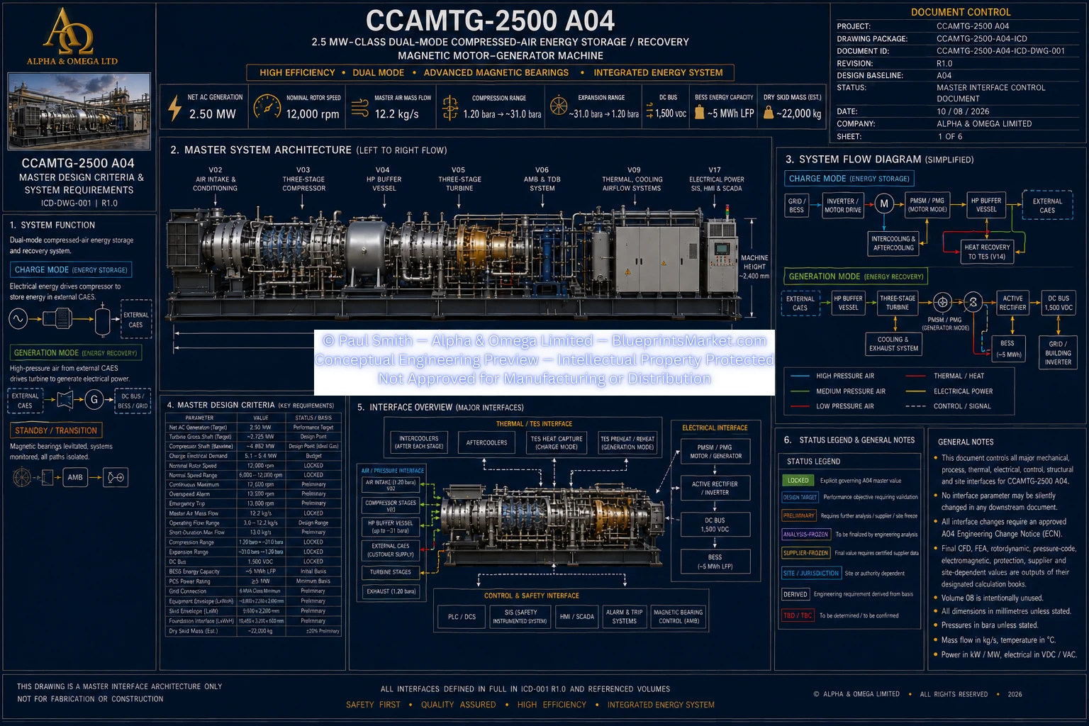
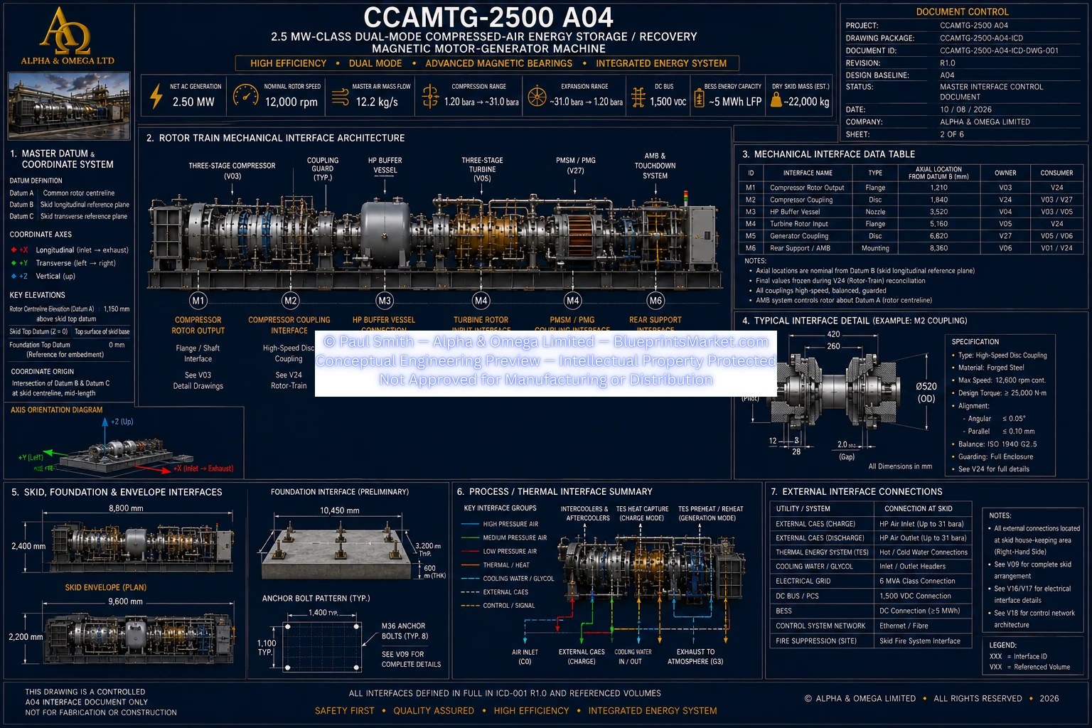
ICD — Master System Interface Architecture

Master System Interface Architecture Sheet 1 of 5
© Paul Smith — Alpha & Omega Limited — PlatformClouds.com — Conceptual Engineering Preview — Not Approved for Manufacturing
Master System Interface Architecture Sheet 1 of 6
© Paul Smith — Alpha & Omega Limited — PlatformClouds.com — Conceptual Engineering Preview — Not Approved for Manufacturing
Master System Interface Architecture Sheet 2 of 6
© Paul Smith — Alpha & Omega Limited — PlatformClouds.com — Conceptual Engineering Preview — Not Approved for Manufacturing
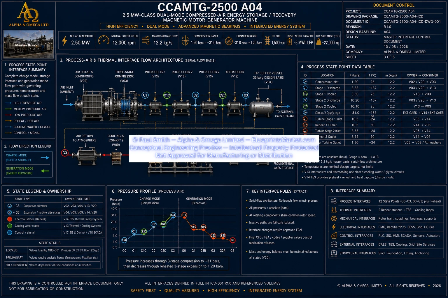
Master System Interface Architecture Sheet 3 of 6
© Paul Smith — Alpha & Omega Limited — PlatformClouds.com — Conceptual Engineering Preview — Not Approved for Manufacturing
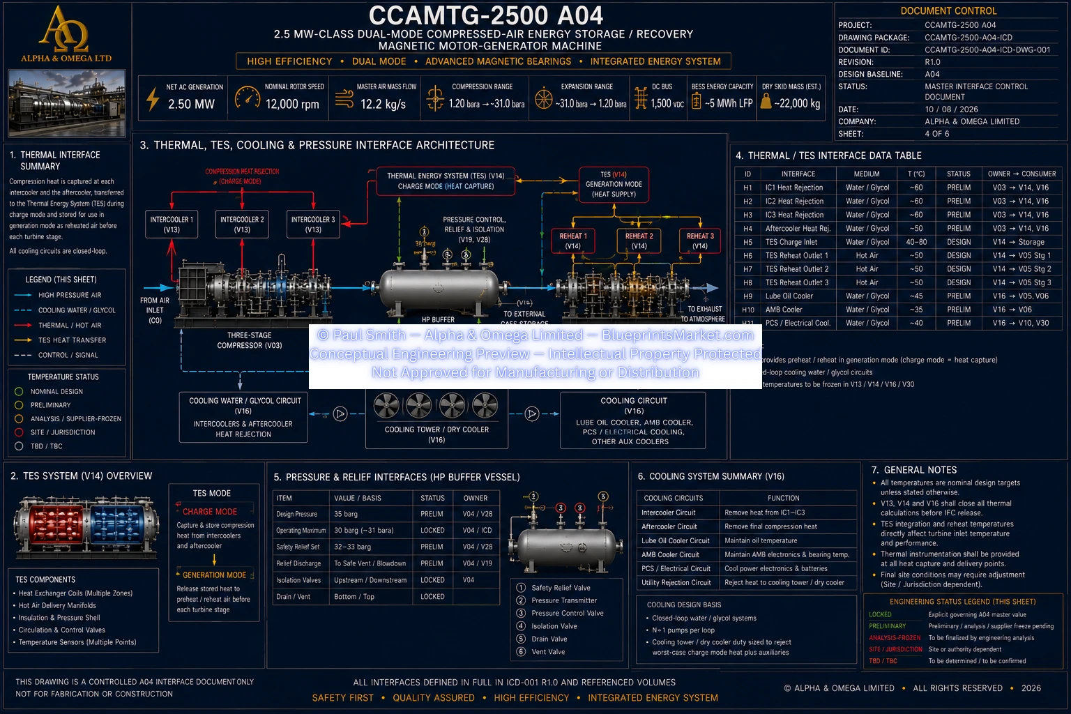
Master System Interface Architecture Sheet 4 of 6
© Paul Smith — Alpha & Omega Limited — PlatformClouds.com — Conceptual Engineering Preview — Not Approved for Manufacturing
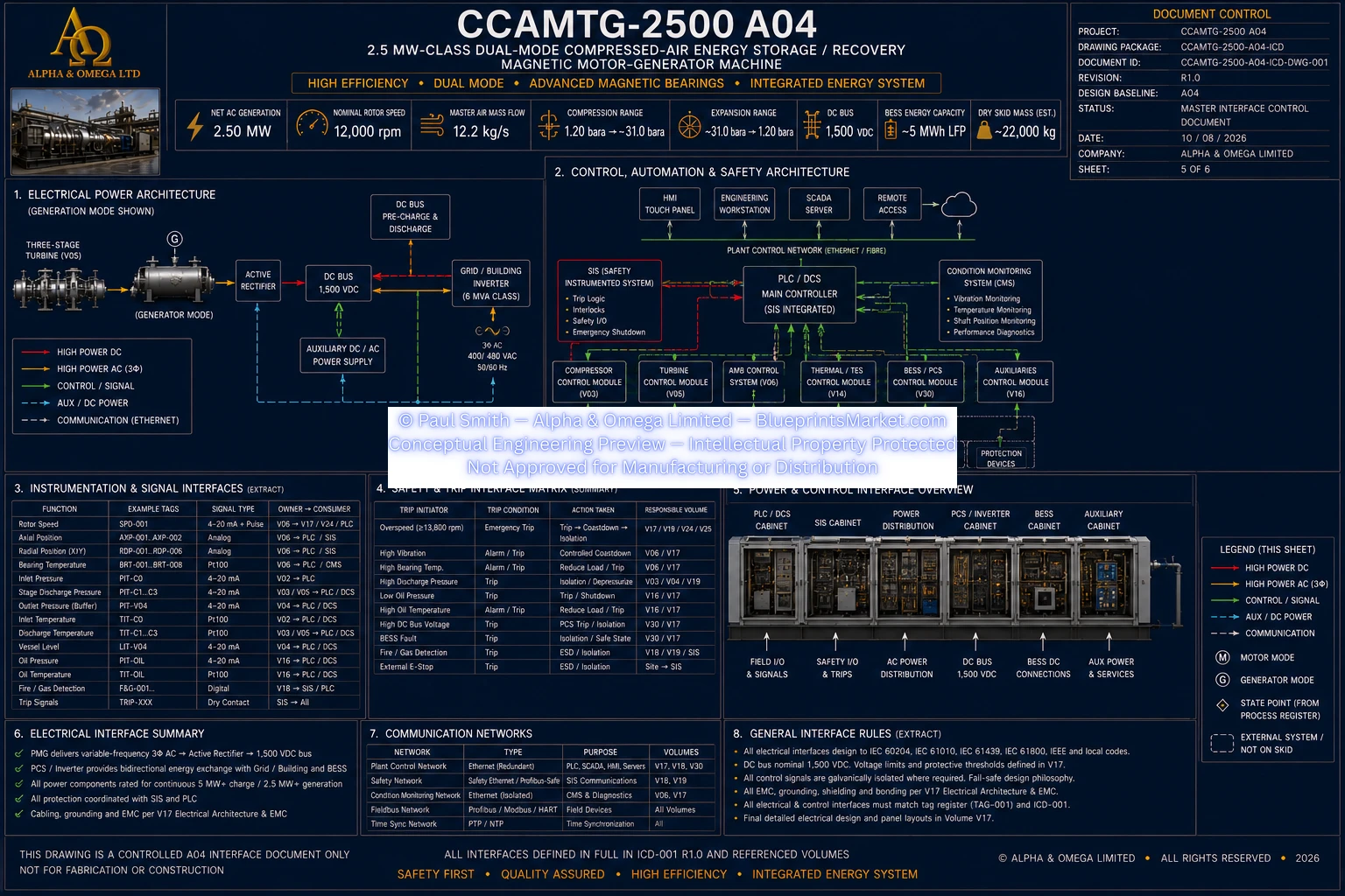
Master System Interface Architecture Sheet 5 of 6
© Paul Smith — Alpha & Omega Limited — PlatformClouds.com — Conceptual Engineering Preview — Not Approved for Manufacturing
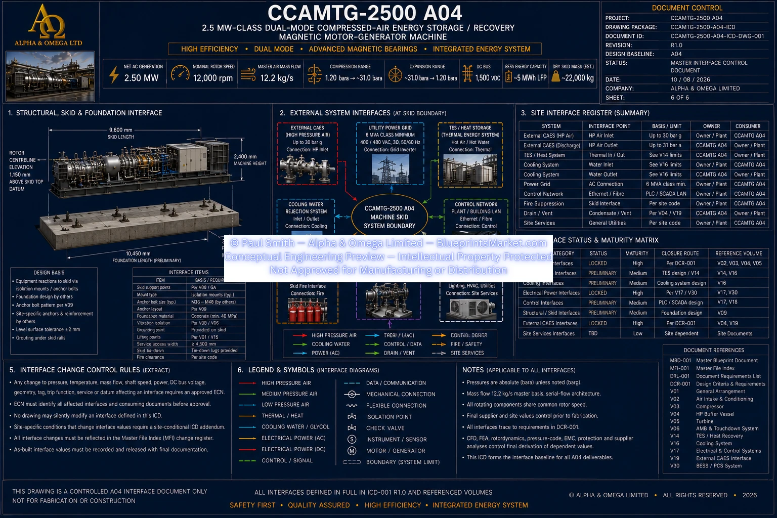
Master System Interface Architecture Sheet 6 of 6
© Paul Smith — Alpha & Omega Limited — PlatformClouds.com — Conceptual Engineering Preview — Not Approved for Manufacturing

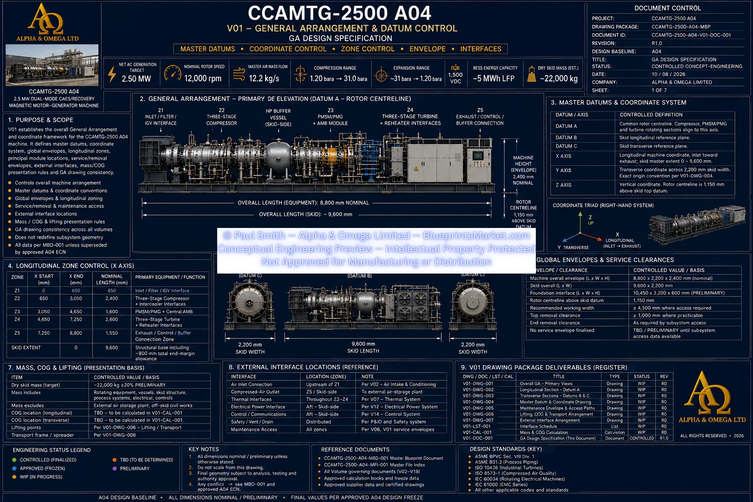
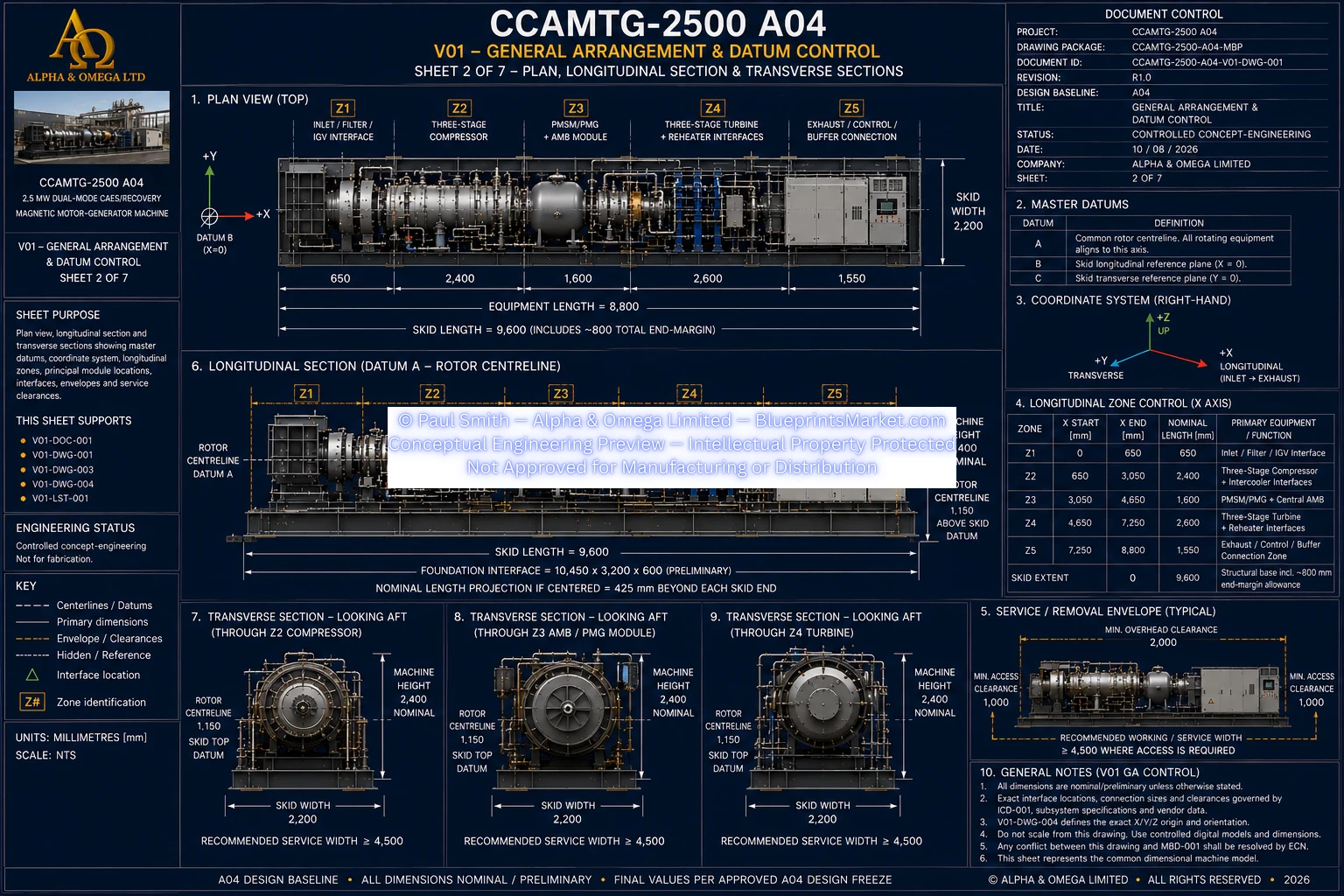
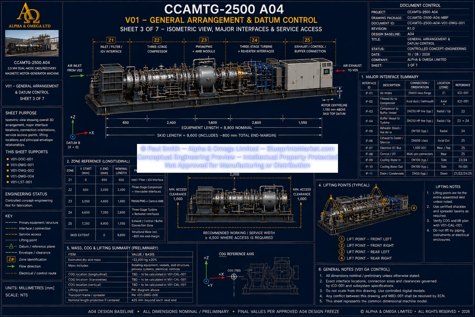
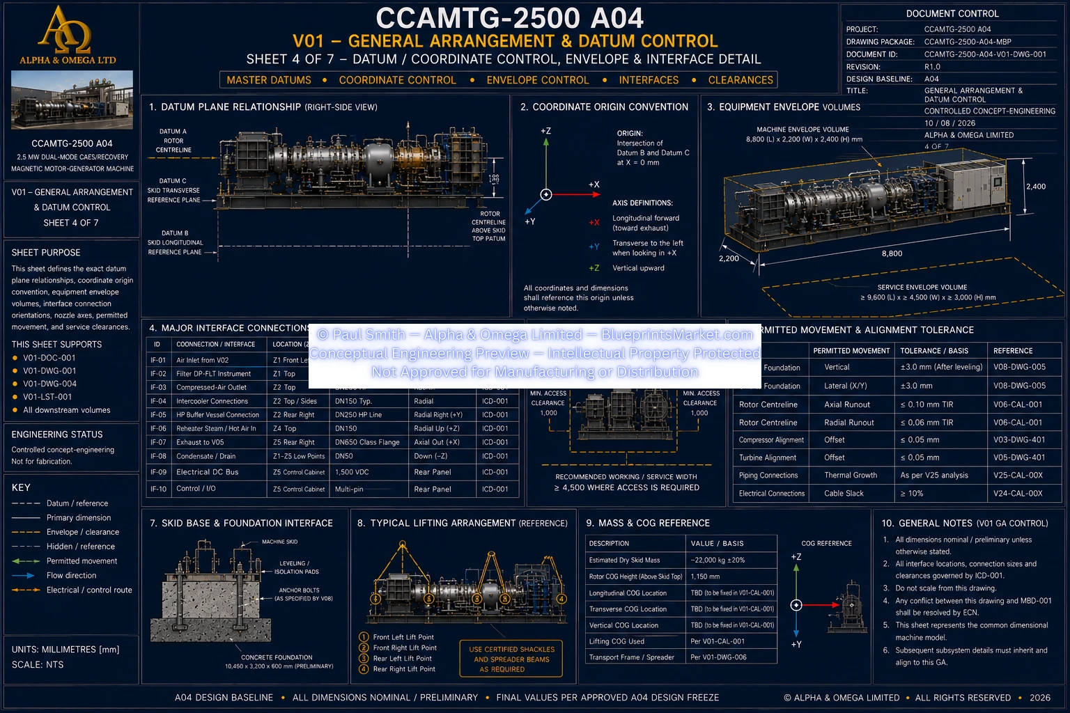
V01 — General Arrangement & Datum Control

V01 General Arrangement Datum Control Sheet 1 of 7
© Paul Smith — Alpha & Omega Limited — PlatformClouds.com — Conceptual Engineering Preview — Not Approved for Manufacturing
V01 General Arrangement Datum Control Sheet 2 of 7
© Paul Smith — Alpha & Omega Limited — PlatformClouds.com — Conceptual Engineering Preview — Not Approved for Manufacturing
V01 General Arrangement Datum Control Sheet 3 of 7
© Paul Smith — Alpha & Omega Limited — PlatformClouds.com — Conceptual Engineering Preview — Not Approved for Manufacturing
V01 General Arrangement Datum Control Sheet 4 of 7
© Paul Smith — Alpha & Omega Limited — PlatformClouds.com — Conceptual Engineering Preview — Not Approved for Manufacturing
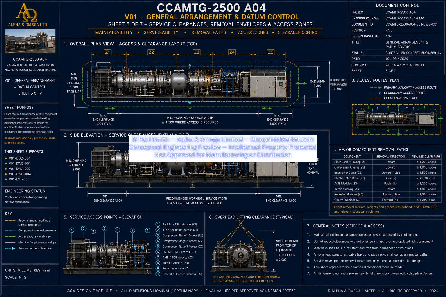
V01 General Arrangement Datum Control Sheet 5 of 7
© Paul Smith — Alpha & Omega Limited — PlatformClouds.com — Conceptual Engineering Preview — Not Approved for Manufacturing
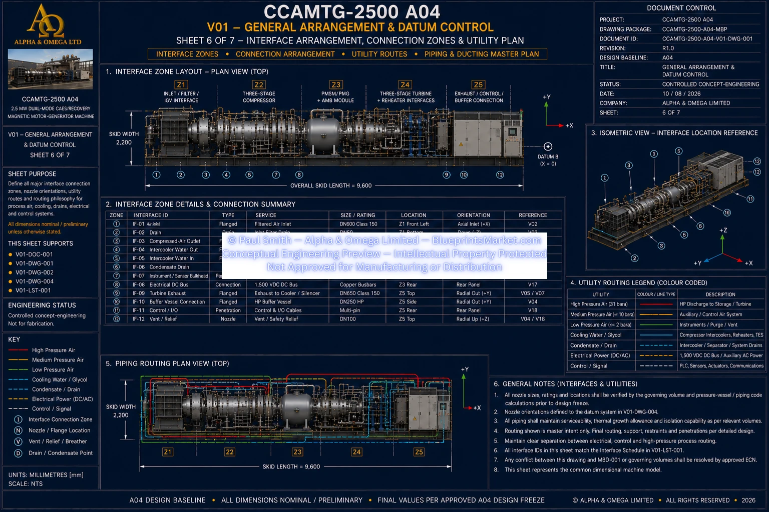
V01 General Arrangement Datum Control Sheet 6 of 7
© Paul Smith — Alpha & Omega Limited — PlatformClouds.com — Conceptual Engineering Preview — Not Approved for Manufacturing
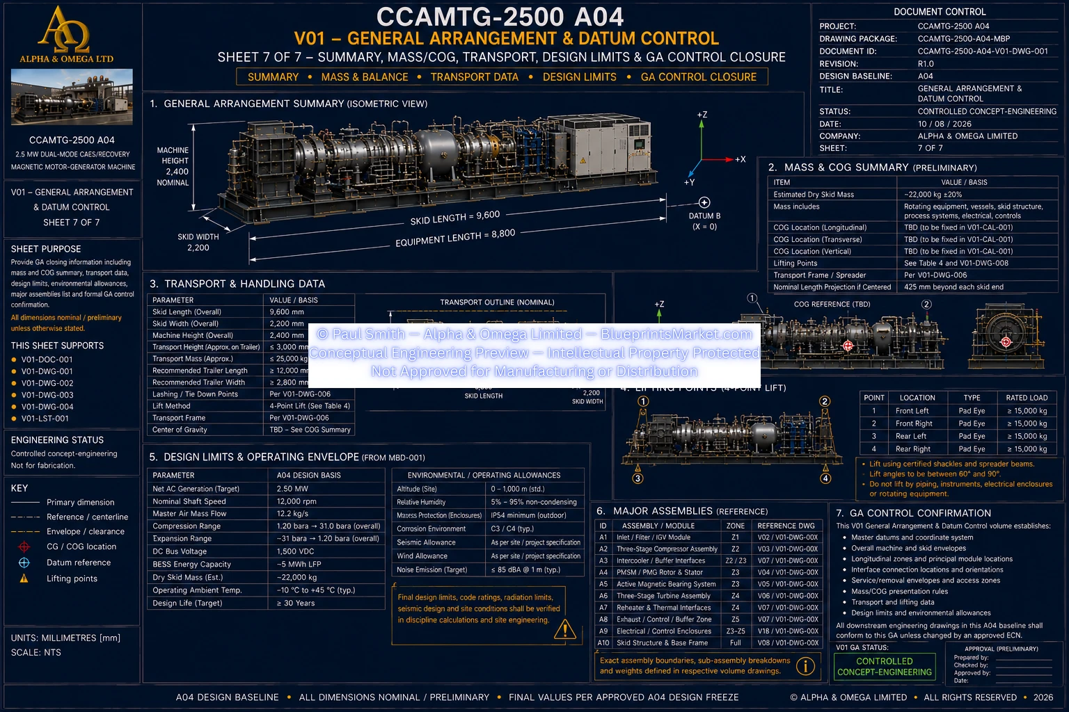
V01 General Arrangement Datum Control Sheet 7 of 7
© Paul Smith — Alpha & Omega Limited — PlatformClouds.com — Conceptual Engineering Preview — Not Approved for Manufacturing

V02 — Air Intake & Conditioning

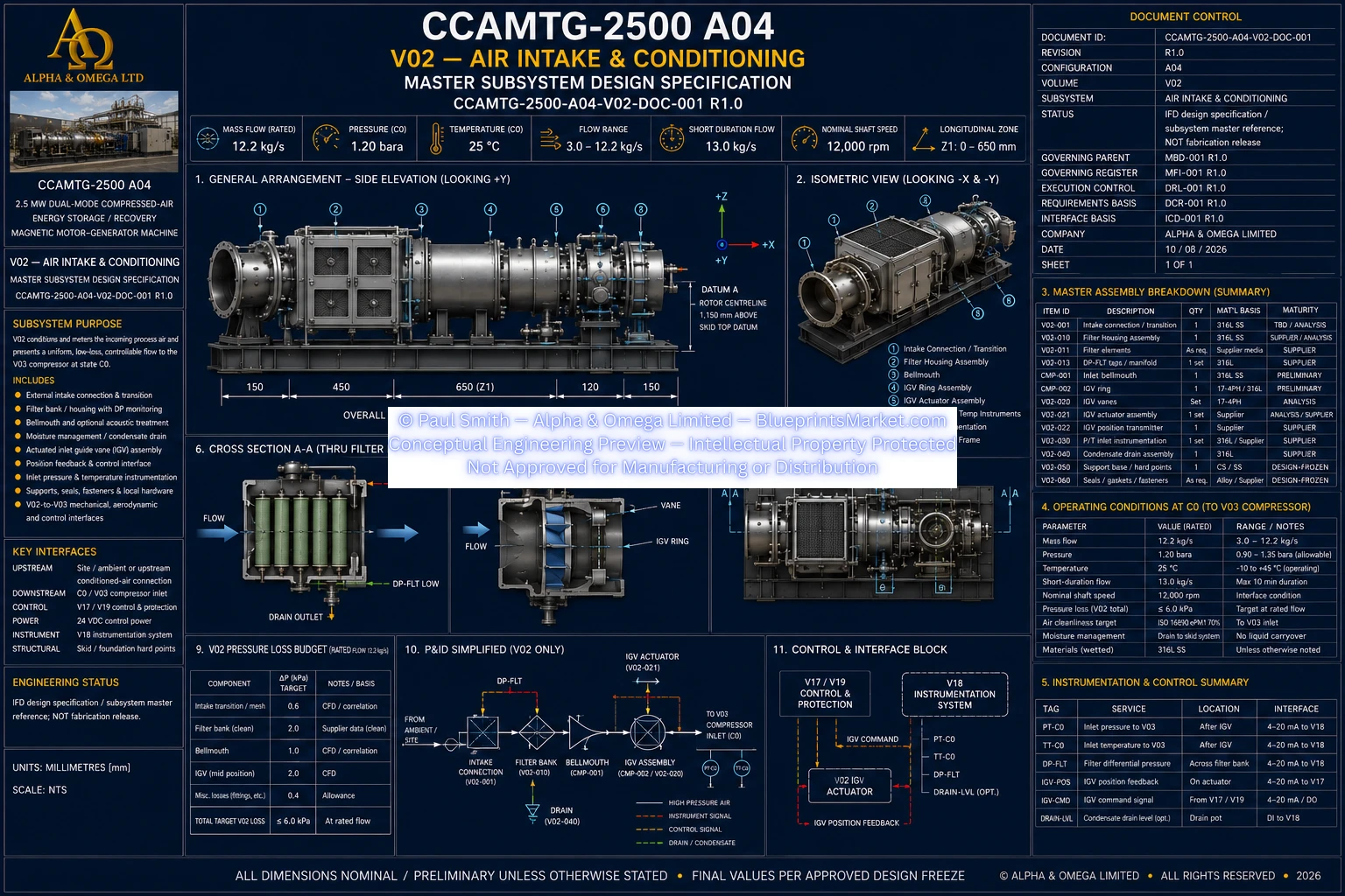
V02 Air Intake Conditioning Sheet 1 of 1
© Paul Smith — Alpha & Omega Limited — PlatformClouds.com — Conceptual Engineering Preview — Not Approved for Manufacturing

V03 — Three-Stage Centrifugal Compressor

V03 Three-Stage Centrifugal Compressor Exploded Assembly Cutaway View
© Paul Smith — Alpha & Omega Limited — PlatformClouds.com — Conceptual Engineering Preview — Not Approved for Manufacturing
V03 Three-Stage Centrifugal Compressor Sheet 1 of 1
© Paul Smith — Alpha & Omega Limited — PlatformClouds.com — Conceptual Engineering Preview — Not Approved for Manufacturing

V04 — HP Buffer / Flow Stabilization Vessel

V04 HP Buffer Flow Stabilization Vessel Exploded Assembly and Cutaway View
© Paul Smith — Alpha & Omega Limited — PlatformClouds.com — Conceptual Engineering Preview — Not Approved for Manufacturing
V04 HP Buffer Flow Stabilization Vessel Sheet 1 of 1
© Paul Smith — Alpha & Omega Limited — PlatformClouds.com — Conceptual Engineering Preview — Not Approved for Manufacturing

V05 — Three-Stage Turbine

V05 Turbine Assembly GA Sheet 1 of 1
© Paul Smith — Alpha & Omega Limited — PlatformClouds.com — Conceptual Engineering Preview — Not Approved for Manufacturing

V06 — Active Magnetic Bearings & Touchdown System

V06 Active Magnetic Bearings Touchdown System Sheet 1 of 2
© Paul Smith — Alpha & Omega Limited — PlatformClouds.com — Conceptual Engineering Preview — Not Approved for Manufacturing
V06 Active Magnetic Bearings Touchdown System Sheet 2 of 2
© Paul Smith — Alpha & Omega Limited — PlatformClouds.com — Conceptual Engineering Preview — Not Approved for Manufacturing
V06 Master Blueprint Exploded Cutaway Views
© Paul Smith — Alpha & Omega Limited — PlatformClouds.com — Conceptual Engineering Preview — Not Approved for Manufacturing

V07 — Thermal, Cooling & Airflow Systems

V07 Thermal Cooling Airflow Systems Exploded Assembly Cutaway
© Paul Smith — Alpha & Omega Limited — PlatformClouds.com — Conceptual Engineering Preview — Not Approved for Manufacturing
V07 Thermal Cooling Airflow Systems Sheet 1 of 2
© Paul Smith — Alpha & Omega Limited — PlatformClouds.com — Conceptual Engineering Preview — Not Approved for Manufacturing
V07 Thermal Cooling Airflow Systems Sheet 2 of 2
© Paul Smith — Alpha & Omega Limited — PlatformClouds.com — Conceptual Engineering Preview — Not Approved for Manufacturing

V08 — Structural Skid & Foundation Interface

V08 Structural Skid Foundation Interface Sheet 1 of 2
© Paul Smith — Alpha & Omega Limited — PlatformClouds.com — Conceptual Engineering Preview — Not Approved for Manufacturing
V08 Structural Skid Foundation Interface Sheet 2 of 2
© Paul Smith — Alpha & Omega Limited — PlatformClouds.com — Conceptual Engineering Preview — Not Approved for Manufacturing

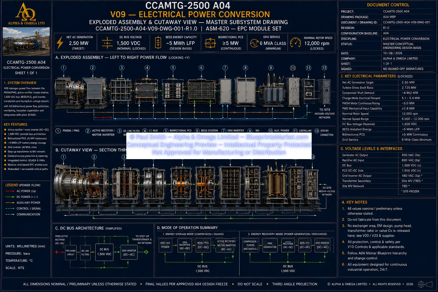
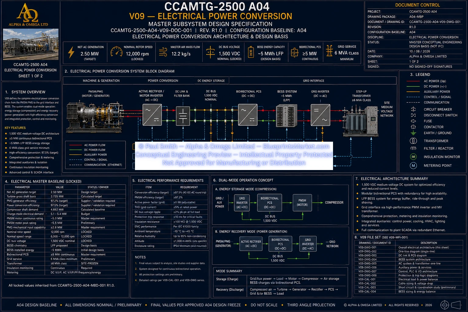
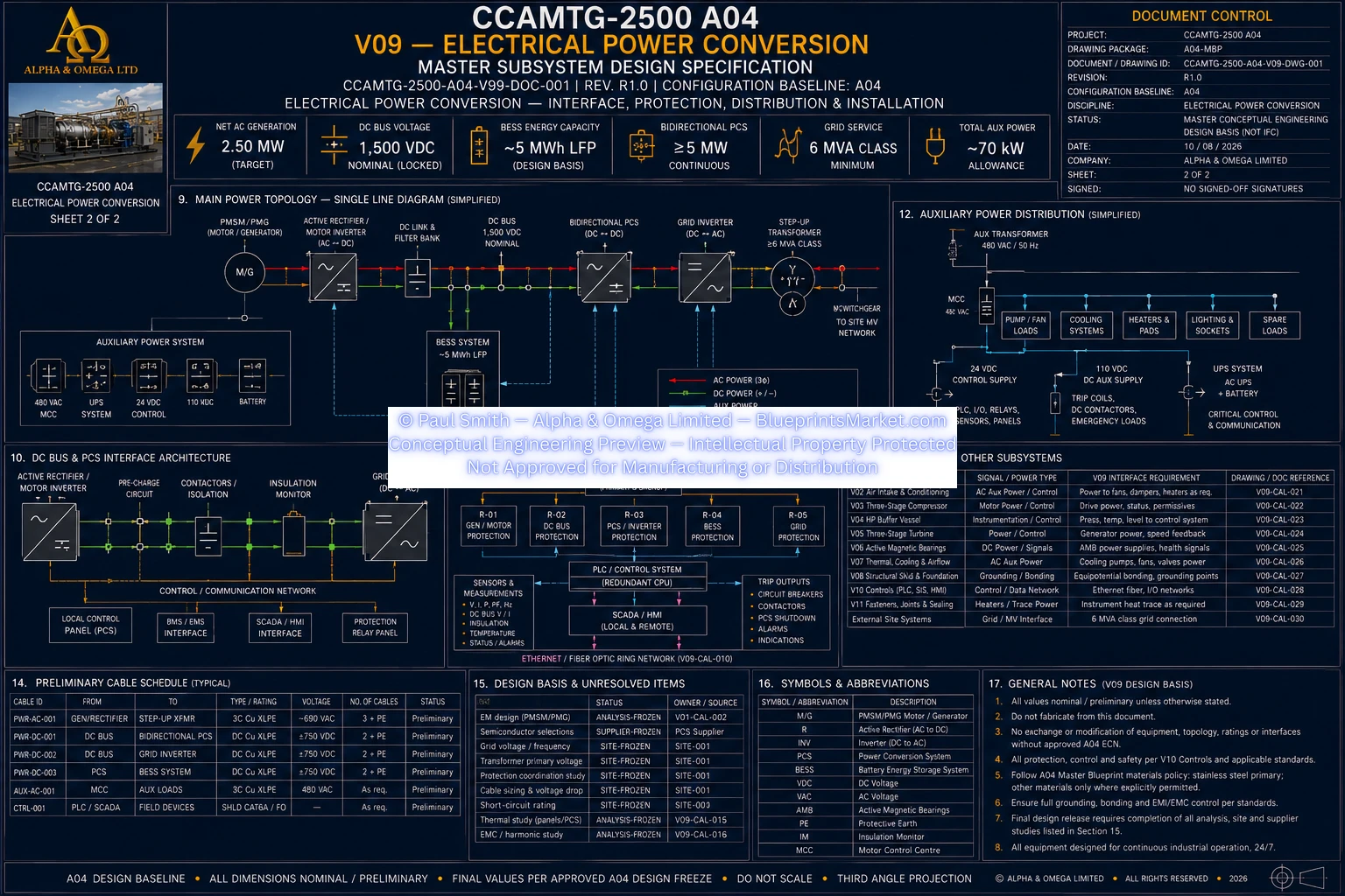
V09 — Electrical Power Conversion

V09 Electrical Power Conversion Exploded Assembly and Cutaway View
© Paul Smith — Alpha & Omega Limited — PlatformClouds.com — Conceptual Engineering Preview — Not Approved for Manufacturing
V09 Electrical Power Conversion System Architecture Sheet 1 of 2
© Paul Smith — Alpha & Omega Limited — PlatformClouds.com — Conceptual Engineering Preview — Not Approved for Manufacturing
V09 Electrical Power Conversion System Architecture Sheet 2 of 2
© Paul Smith — Alpha & Omega Limited — PlatformClouds.com — Conceptual Engineering Preview — Not Approved for Manufacturing

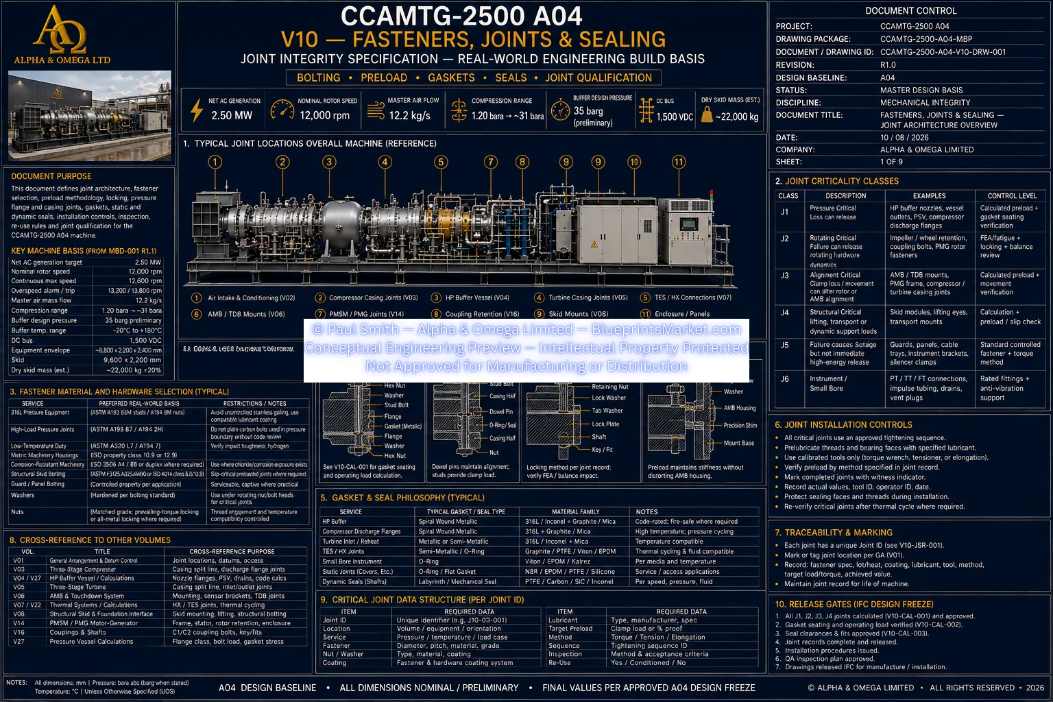
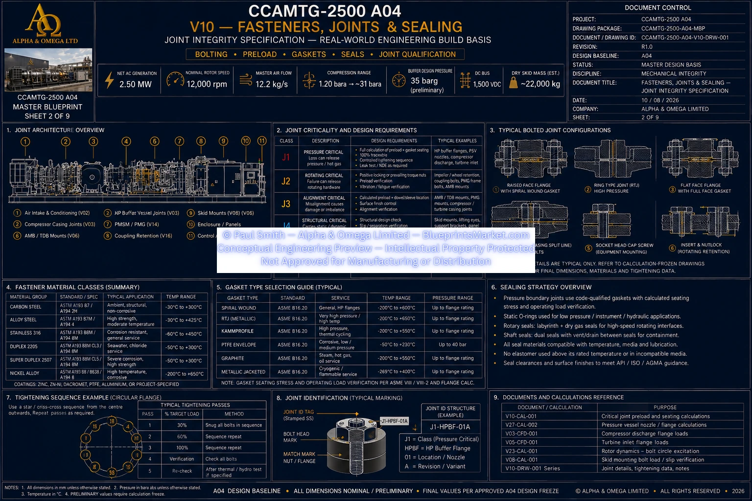
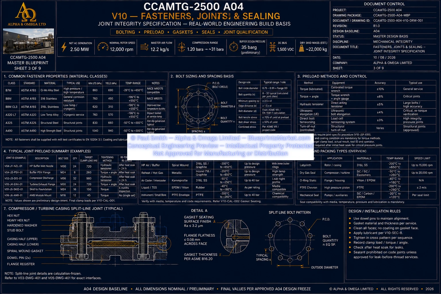
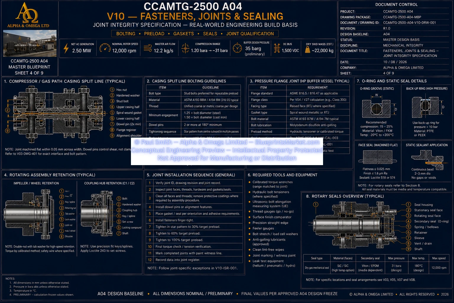
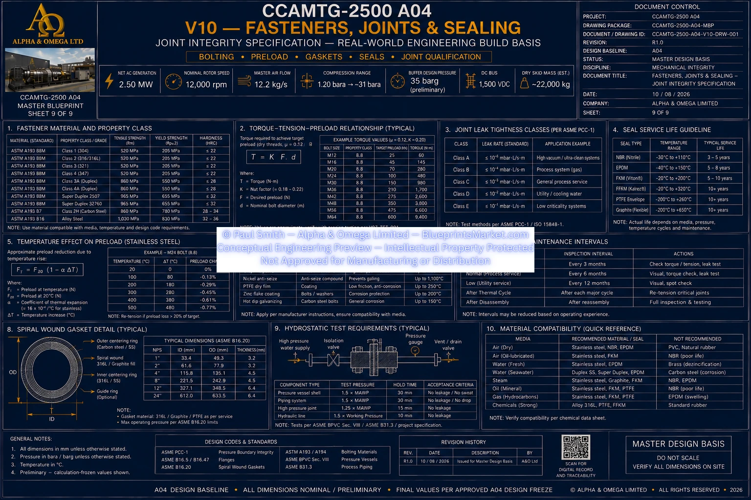
V10 — Fasteners, Joints, Sealing & Joint Integrity

V10 Sheet 01 of 09
© Paul Smith — Alpha & Omega Limited — PlatformClouds.com — Conceptual Engineering Preview — Not Approved for Manufacturing
V10 Sheet 02 of 09
© Paul Smith — Alpha & Omega Limited — PlatformClouds.com — Conceptual Engineering Preview — Not Approved for Manufacturing
V10 Sheet 03 of 09
© Paul Smith — Alpha & Omega Limited — PlatformClouds.com — Conceptual Engineering Preview — Not Approved for Manufacturing
V10 Sheet 04 of 09
© Paul Smith — Alpha & Omega Limited — PlatformClouds.com — Conceptual Engineering Preview — Not Approved for Manufacturing
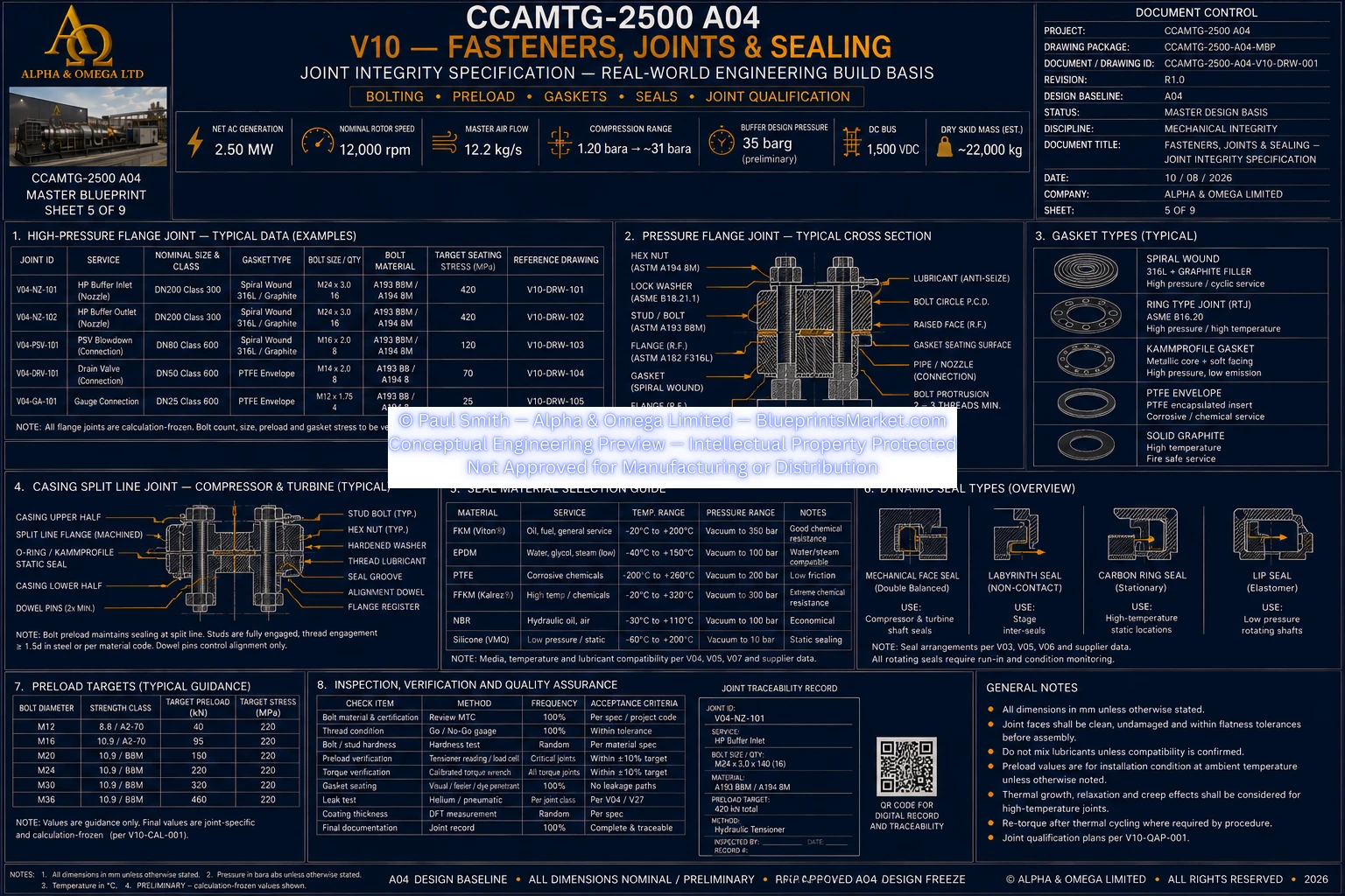
V10 Sheet 05 of 09
© Paul Smith — Alpha & Omega Limited — PlatformClouds.com — Conceptual Engineering Preview — Not Approved for Manufacturing
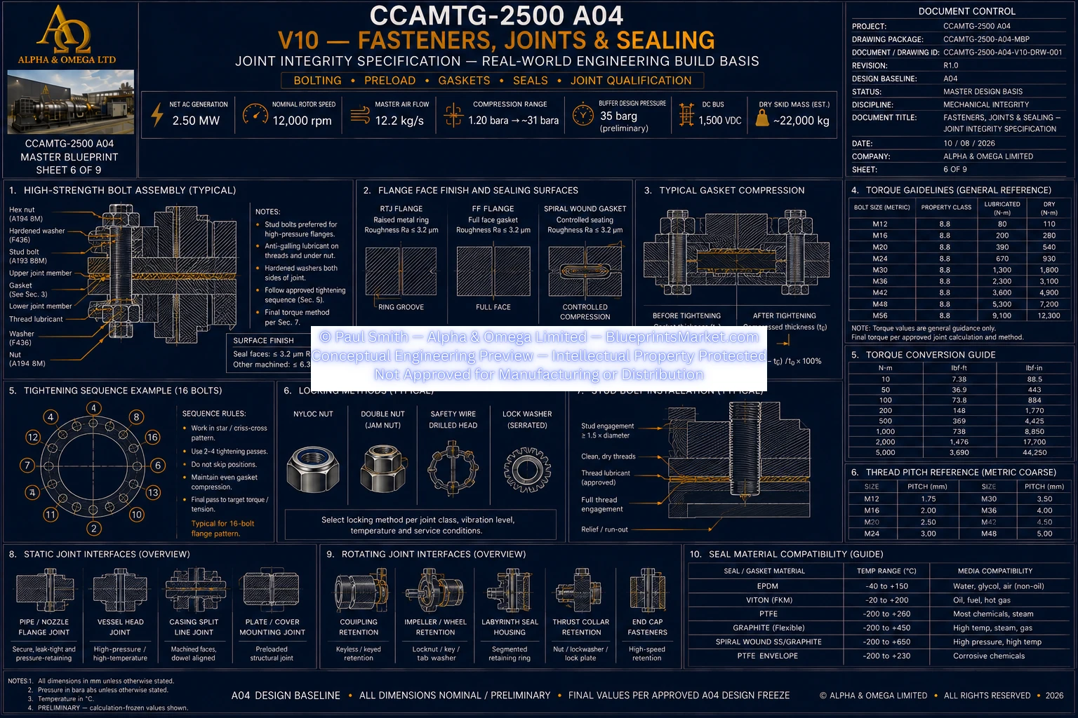
V10 Sheet 06 of 09
© Paul Smith — Alpha & Omega Limited — PlatformClouds.com — Conceptual Engineering Preview — Not Approved for Manufacturing
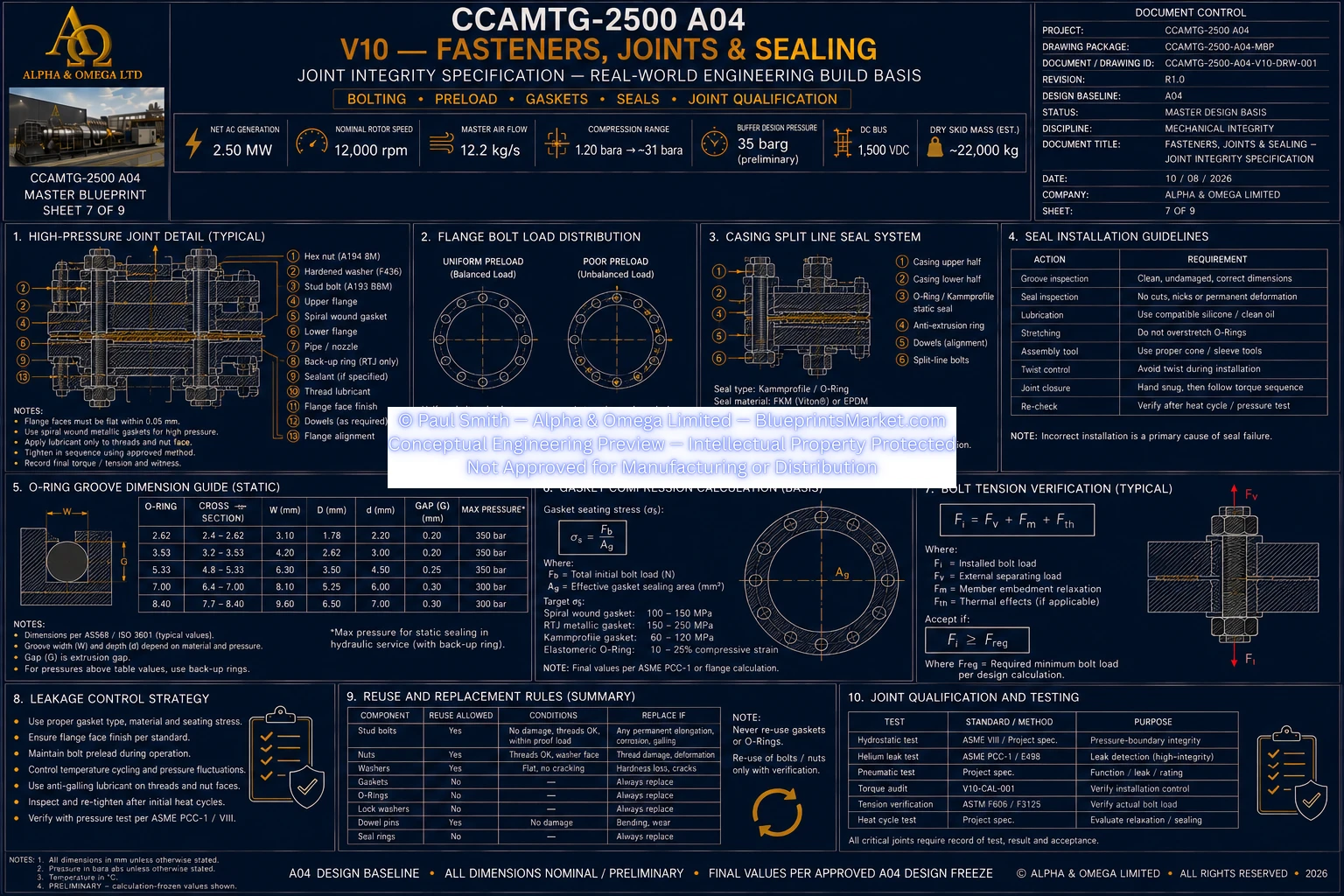
V10 Sheet 07 of 09
© Paul Smith — Alpha & Omega Limited — PlatformClouds.com — Conceptual Engineering Preview — Not Approved for Manufacturing
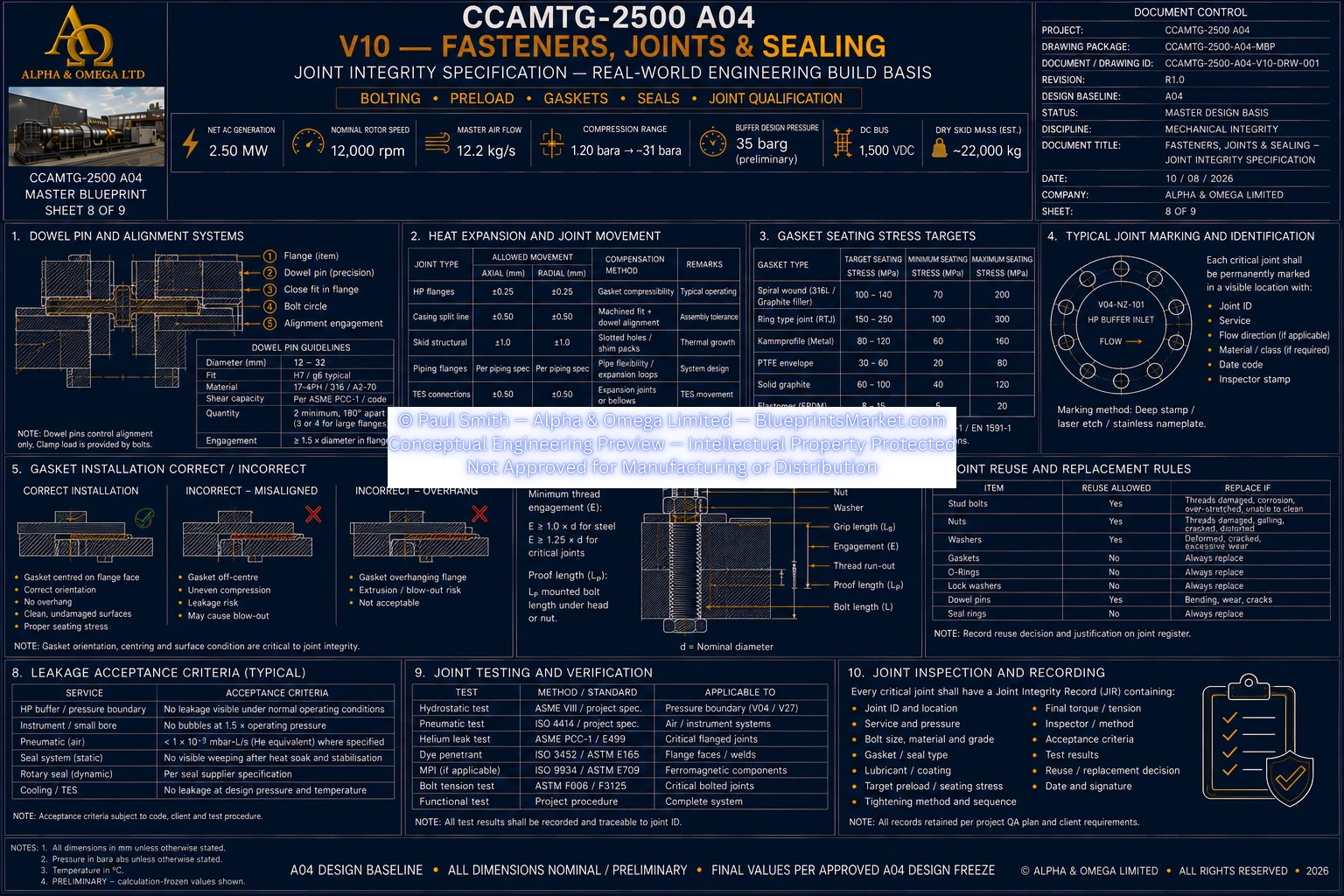
V10 Sheet 08 of 09
© Paul Smith — Alpha & Omega Limited — PlatformClouds.com — Conceptual Engineering Preview — Not Approved for Manufacturing
V10 Sheet 09 of 09
© Paul Smith — Alpha & Omega Limited — PlatformClouds.com — Conceptual Engineering Preview — Not Approved for Manufacturing

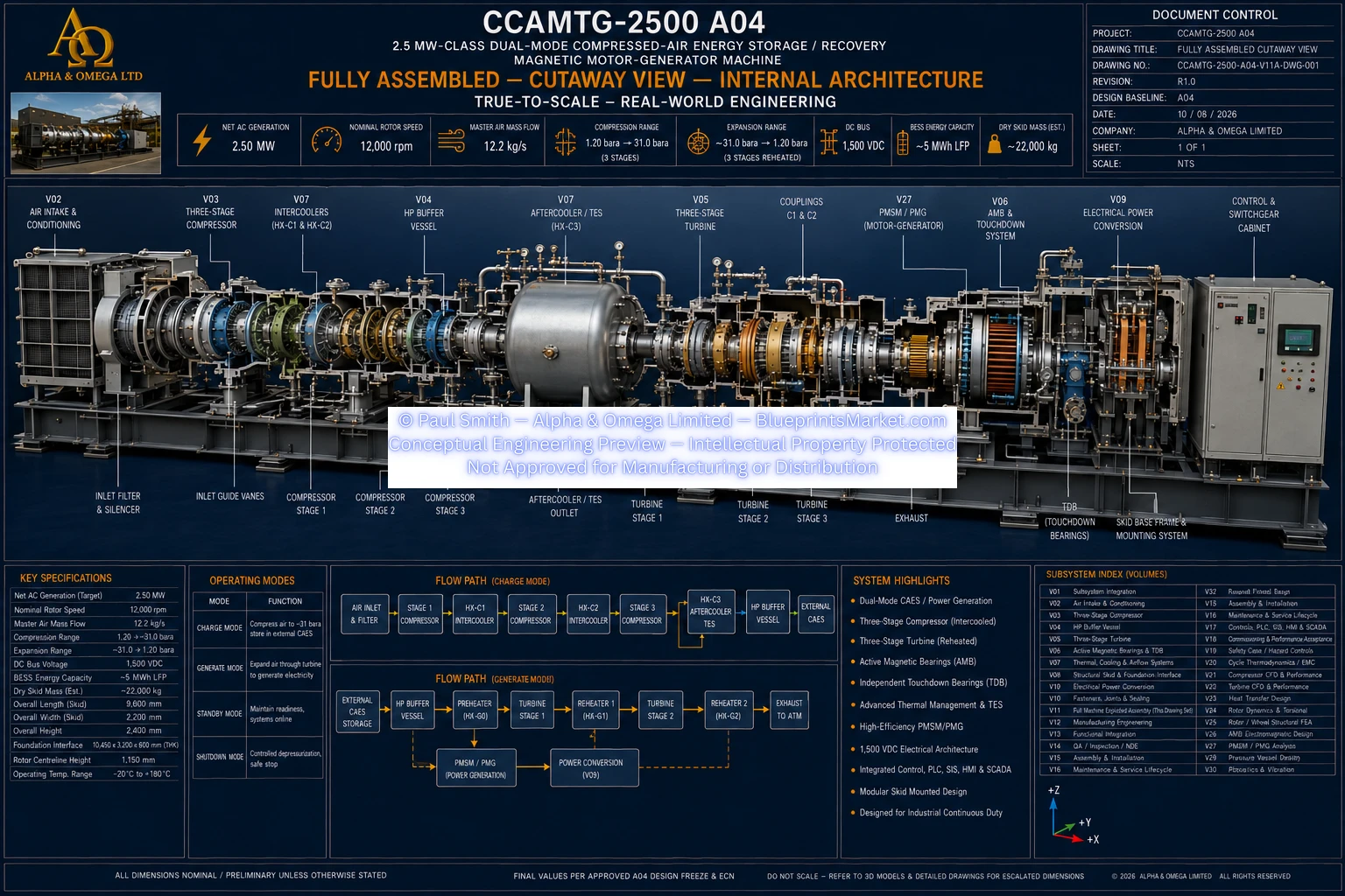
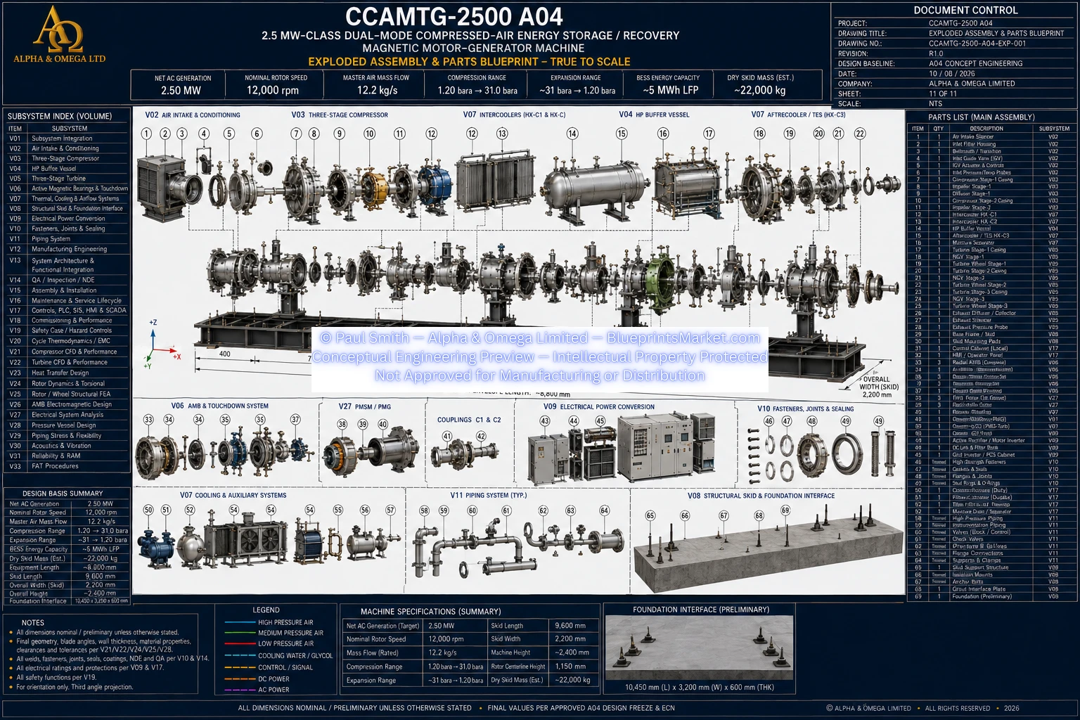
V11 / V11A — Full Machine Exploded Assembly & Parts Identification

V11A Full Machine Exploded Assembly and Parts Identification
© Paul Smith — Alpha & Omega Limited — PlatformClouds.com — Conceptual Engineering Preview — Not Approved for Manufacturing
V11 Full Machine Exploded Assembly and Parts Identification
© Paul Smith — Alpha & Omega Limited — PlatformClouds.com — Conceptual Engineering Preview — Not Approved for Manufacturing

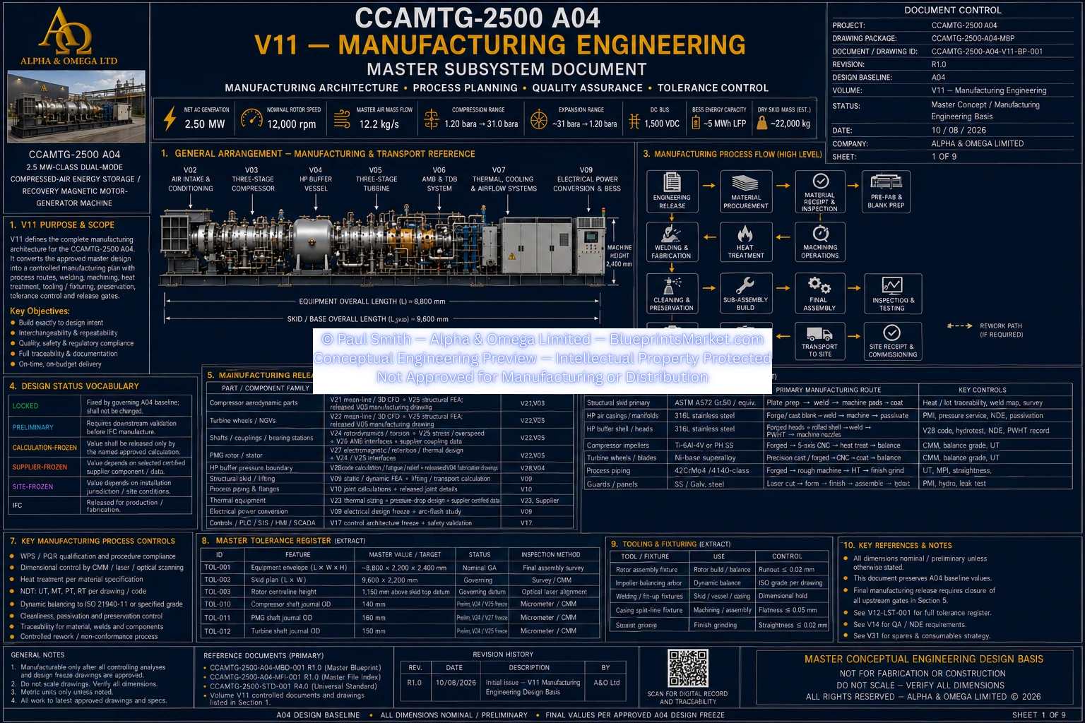
V12 — Manufacturing Engineering

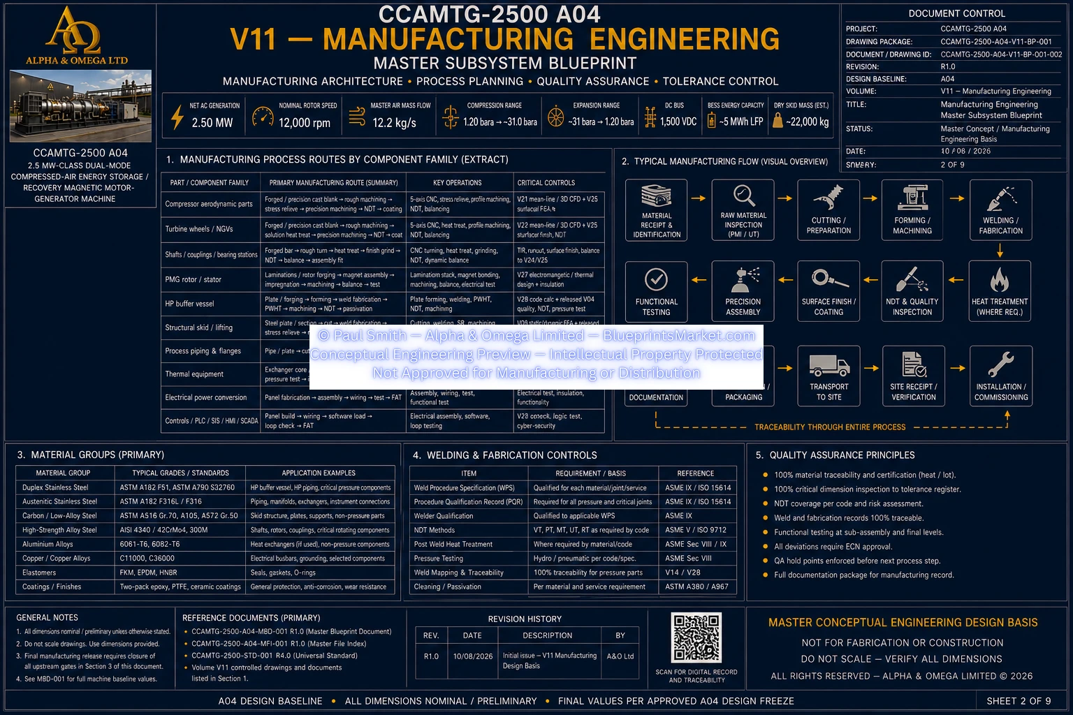
V12 Manufacturing Engineering Sheet 1 of 9
© Paul Smith — Alpha & Omega Limited — PlatformClouds.com — Conceptual Engineering Preview — Not Approved for Manufacturing
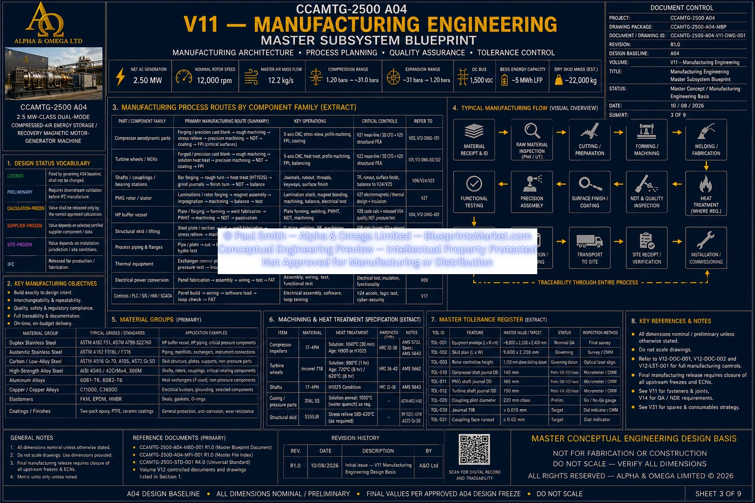
V12 Manufacturing Engineering Sheet 2 of 9
© Paul Smith — Alpha & Omega Limited — PlatformClouds.com — Conceptual Engineering Preview — Not Approved for Manufacturing
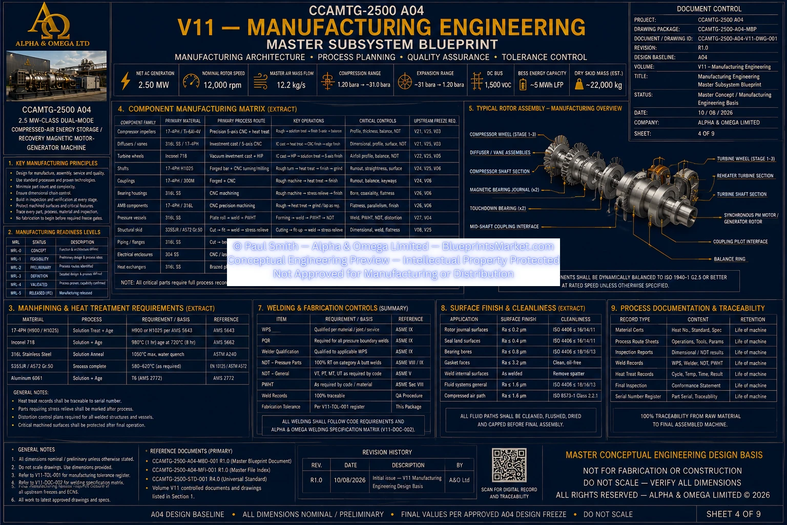
V12 Manufacturing Engineering Sheet 3 of 9
© Paul Smith — Alpha & Omega Limited — PlatformClouds.com — Conceptual Engineering Preview — Not Approved for Manufacturing
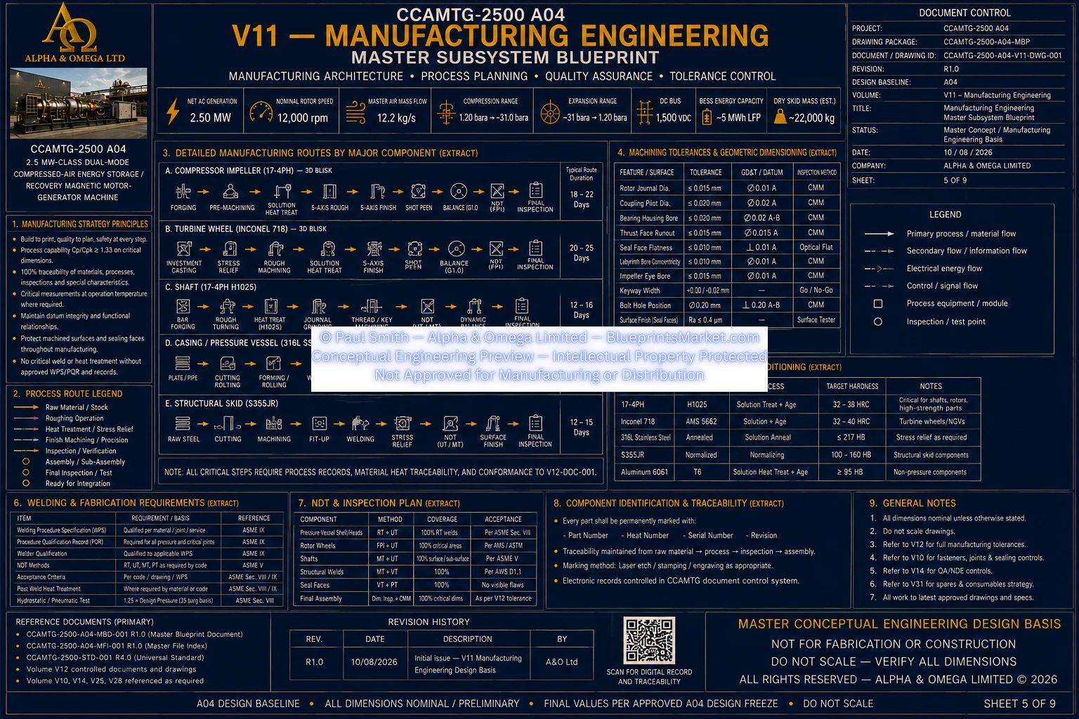
V12 Manufacturing Engineering Sheet 4 of 9
© Paul Smith — Alpha & Omega Limited — PlatformClouds.com — Conceptual Engineering Preview — Not Approved for Manufacturing
V12 Manufacturing Engineering Sheet 5 of 9
© Paul Smith — Alpha & Omega Limited — PlatformClouds.com — Conceptual Engineering Preview — Not Approved for Manufacturing
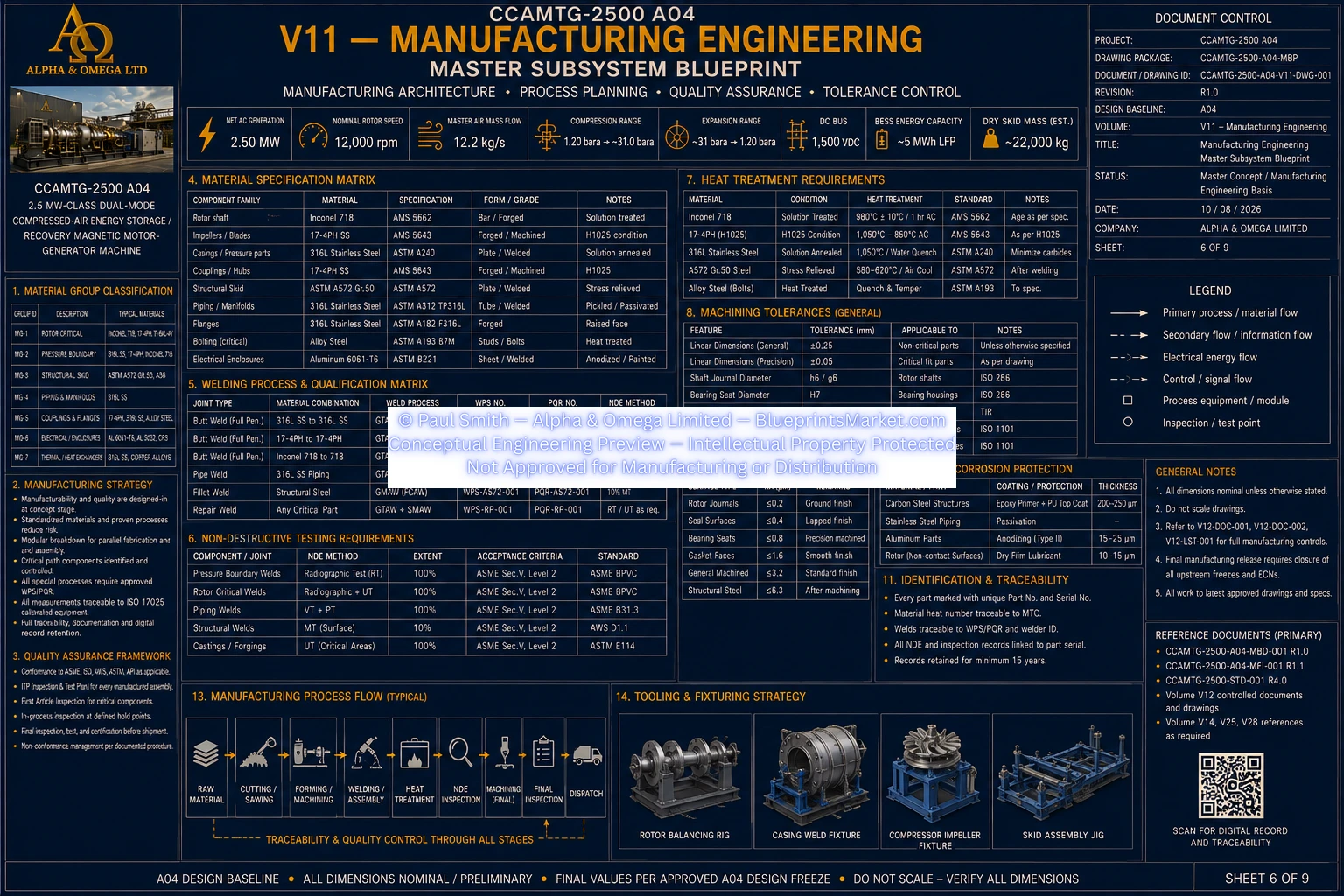
V12 Manufacturing Engineering Sheet 6 of 9
© Paul Smith — Alpha & Omega Limited — PlatformClouds.com — Conceptual Engineering Preview — Not Approved for Manufacturing
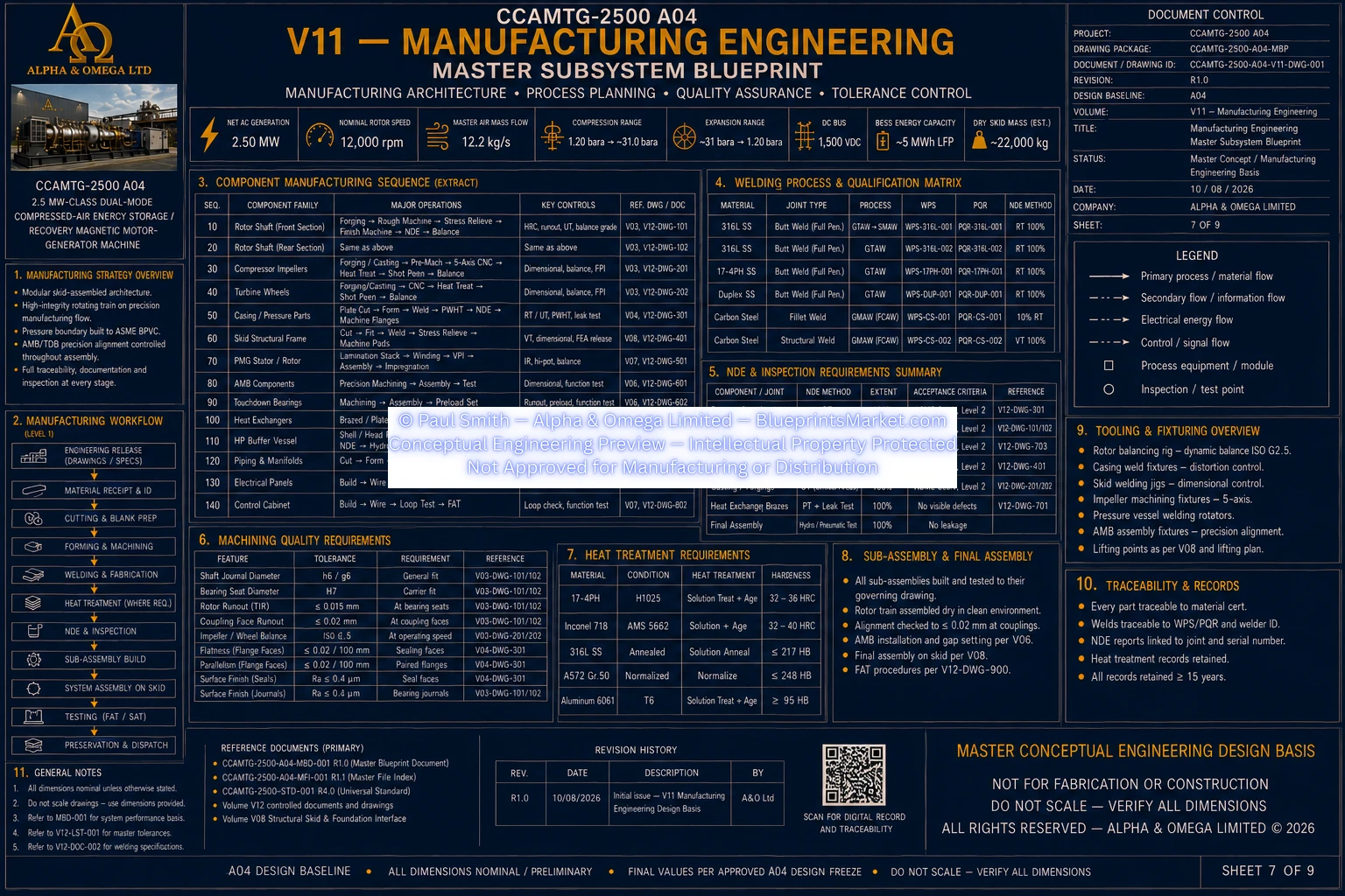
V12 Manufacturing Engineering Sheet 7 of 9
© Paul Smith — Alpha & Omega Limited — PlatformClouds.com — Conceptual Engineering Preview — Not Approved for Manufacturing
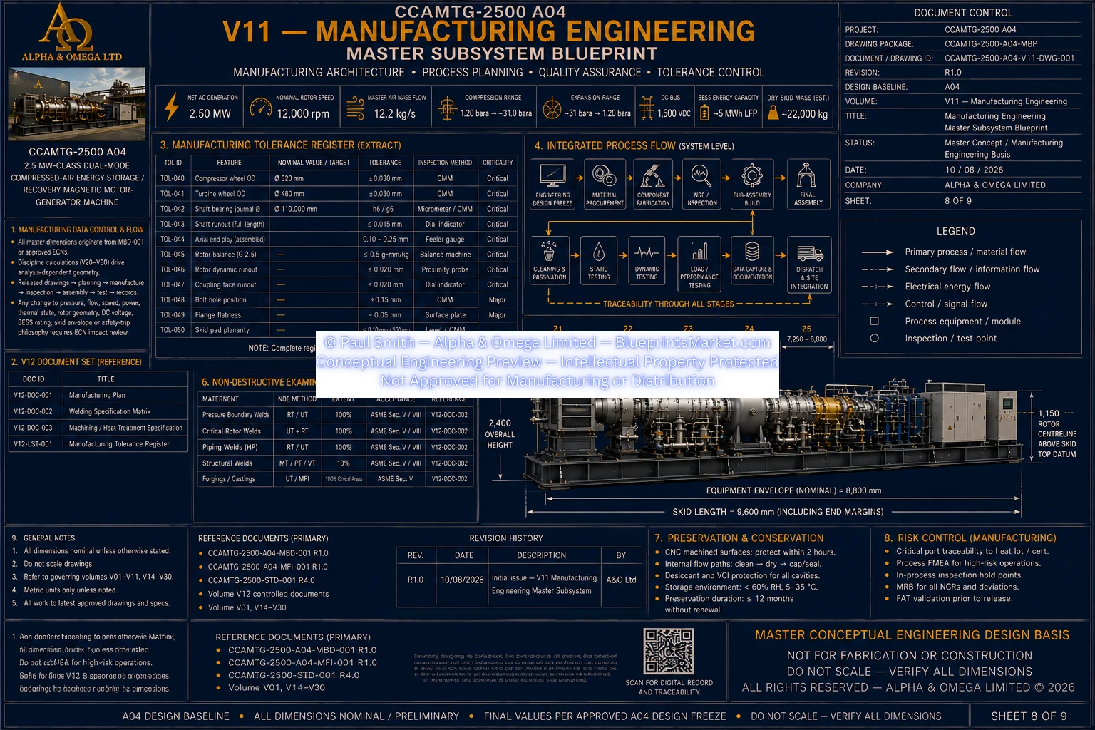
V12 Manufacturing Engineering Sheet 8 of 9
© Paul Smith — Alpha & Omega Limited — PlatformClouds.com — Conceptual Engineering Preview — Not Approved for Manufacturing

V13 — System Architecture & Functional Integration

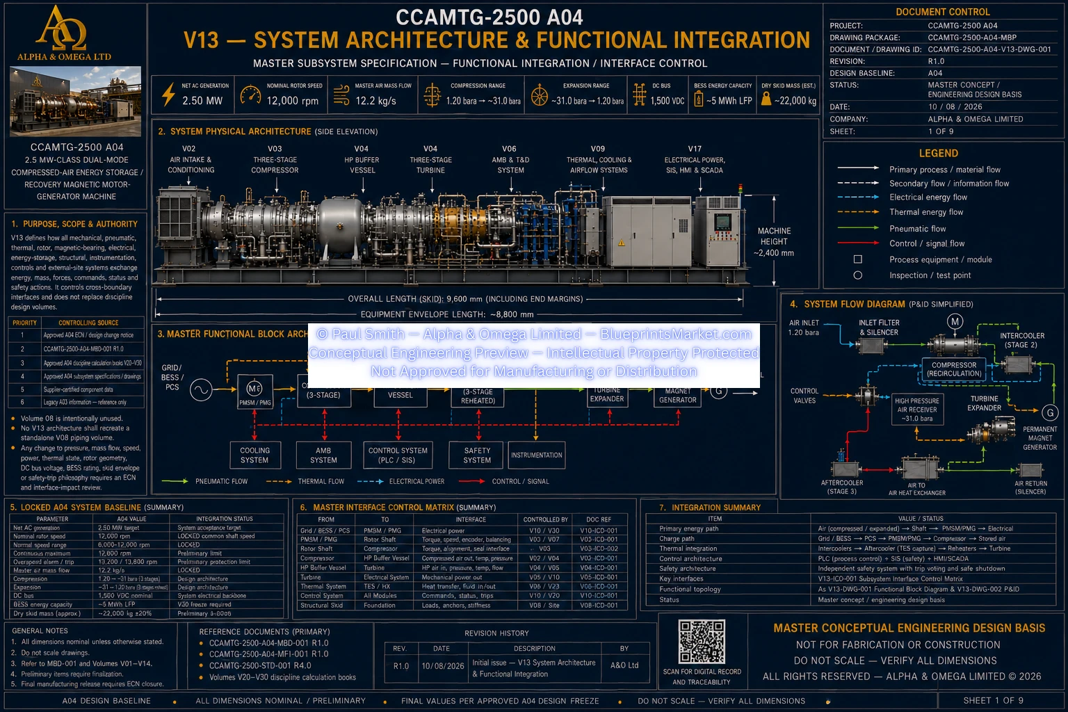
V13 Sheet 1 of 9
© Paul Smith — Alpha & Omega Limited — PlatformClouds.com — Conceptual Engineering Preview — Not Approved for Manufacturing
V13 Sheet 2 of 9
© Paul Smith — Alpha & Omega Limited — PlatformClouds.com — Conceptual Engineering Preview — Not Approved for Manufacturing
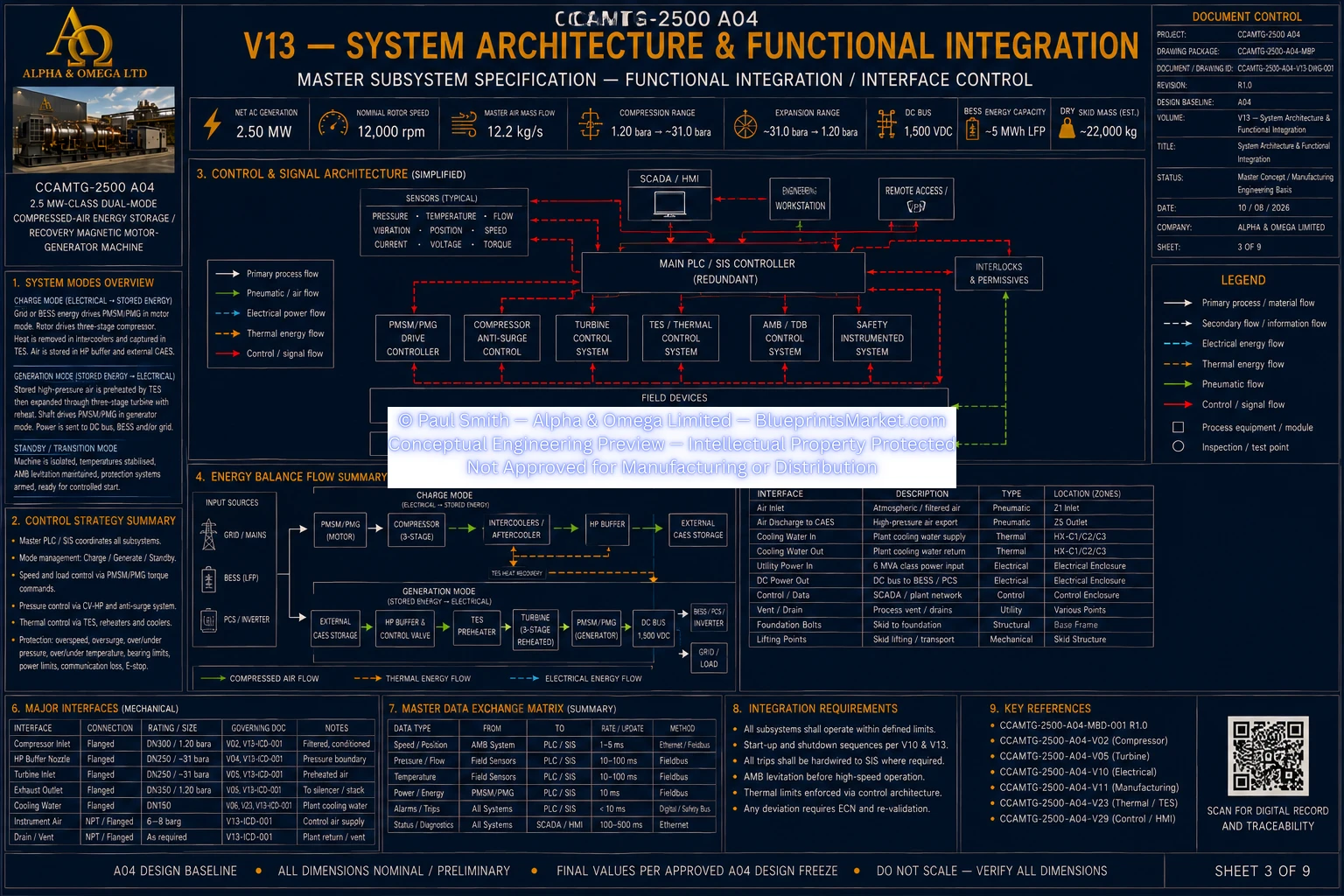
V13 Sheet 3 of 9
© Paul Smith — Alpha & Omega Limited — PlatformClouds.com — Conceptual Engineering Preview — Not Approved for Manufacturing
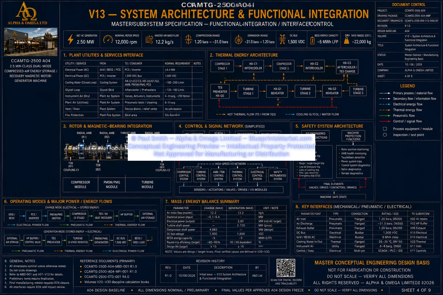
V13 Sheet 4 of 9
© Paul Smith — Alpha & Omega Limited — PlatformClouds.com — Conceptual Engineering Preview — Not Approved for Manufacturing
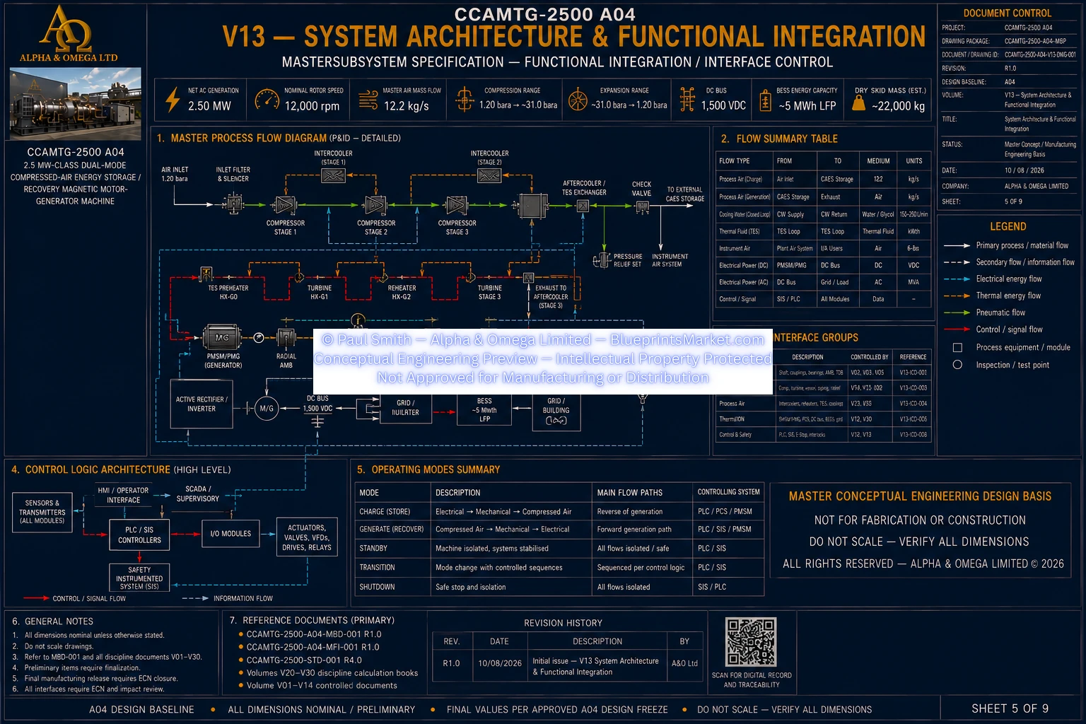
V13 Sheet 5 of 9
© Paul Smith — Alpha & Omega Limited — PlatformClouds.com — Conceptual Engineering Preview — Not Approved for Manufacturing
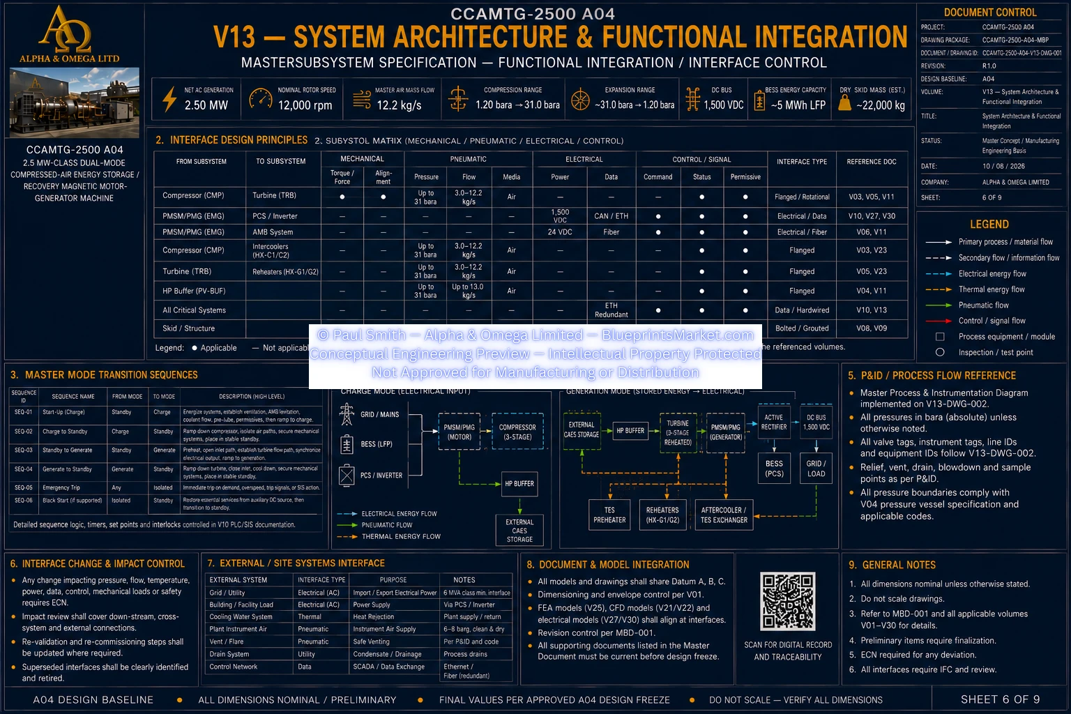
V13 Sheet 6 of 9
© Paul Smith — Alpha & Omega Limited — PlatformClouds.com — Conceptual Engineering Preview — Not Approved for Manufacturing
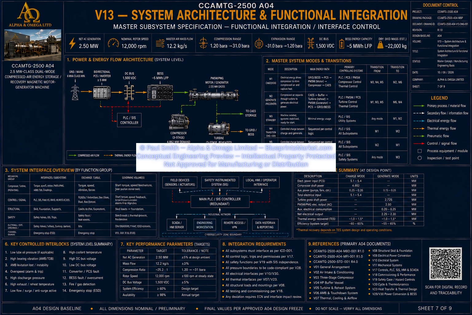
V13 Sheet 7 of 9
© Paul Smith — Alpha & Omega Limited — PlatformClouds.com — Conceptual Engineering Preview — Not Approved for Manufacturing
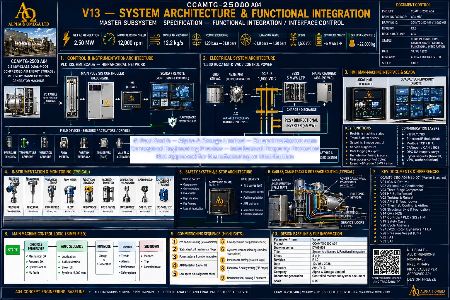
V13 Sheet 8A of 9
© Paul Smith — Alpha & Omega Limited — PlatformClouds.com — Conceptual Engineering Preview — Not Approved for Manufacturing
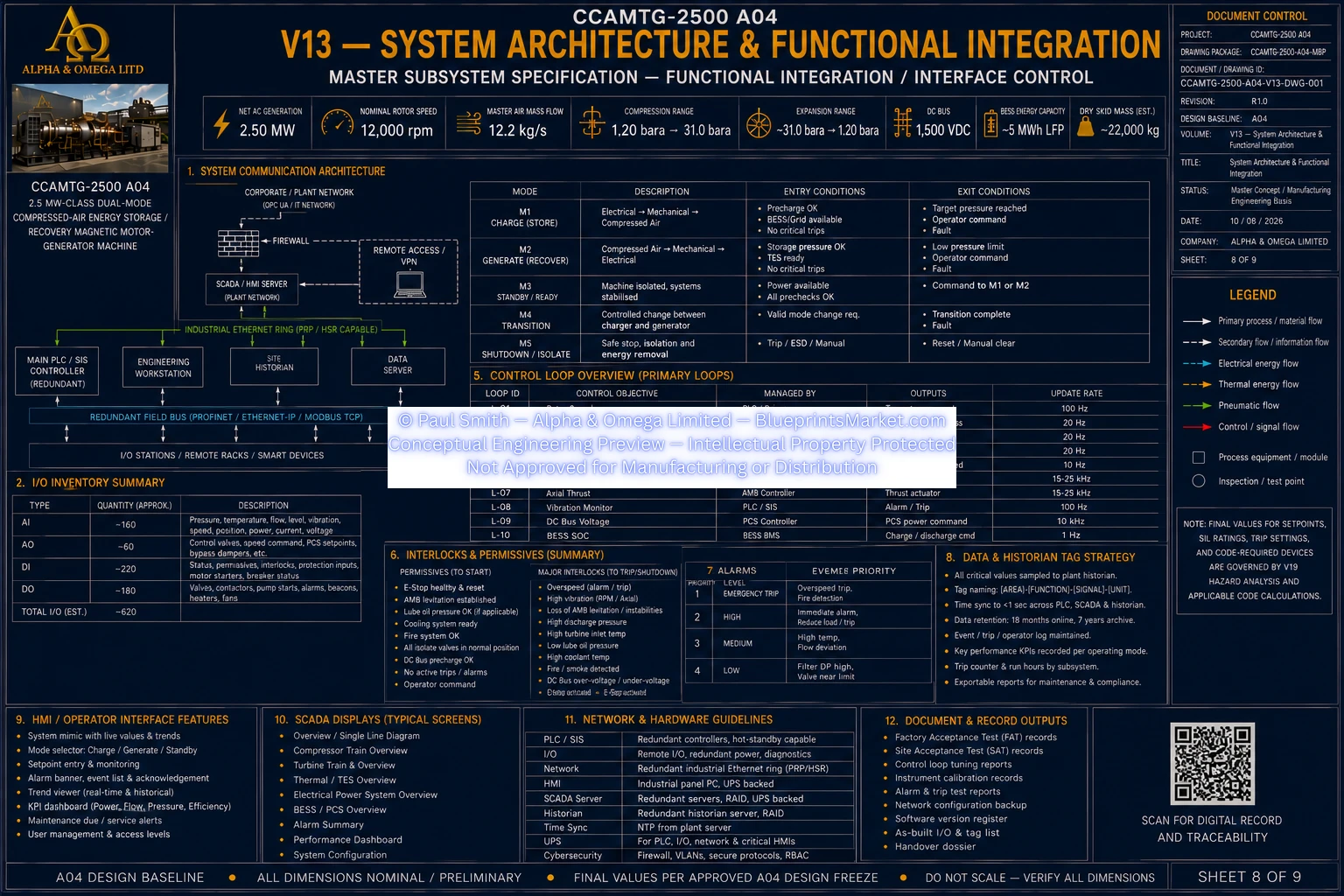
V13 Sheet 8 of 9
© Paul Smith — Alpha & Omega Limited — PlatformClouds.com — Conceptual Engineering Preview — Not Approved for Manufacturing
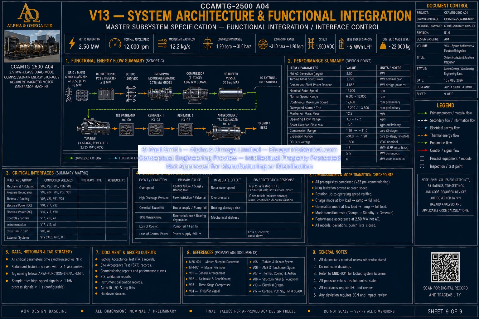
V13 Sheet 9 of 9
© Paul Smith — Alpha & Omega Limited — PlatformClouds.com — Conceptual Engineering Preview — Not Approved for Manufacturing

V14 — QA / Inspection / NDE

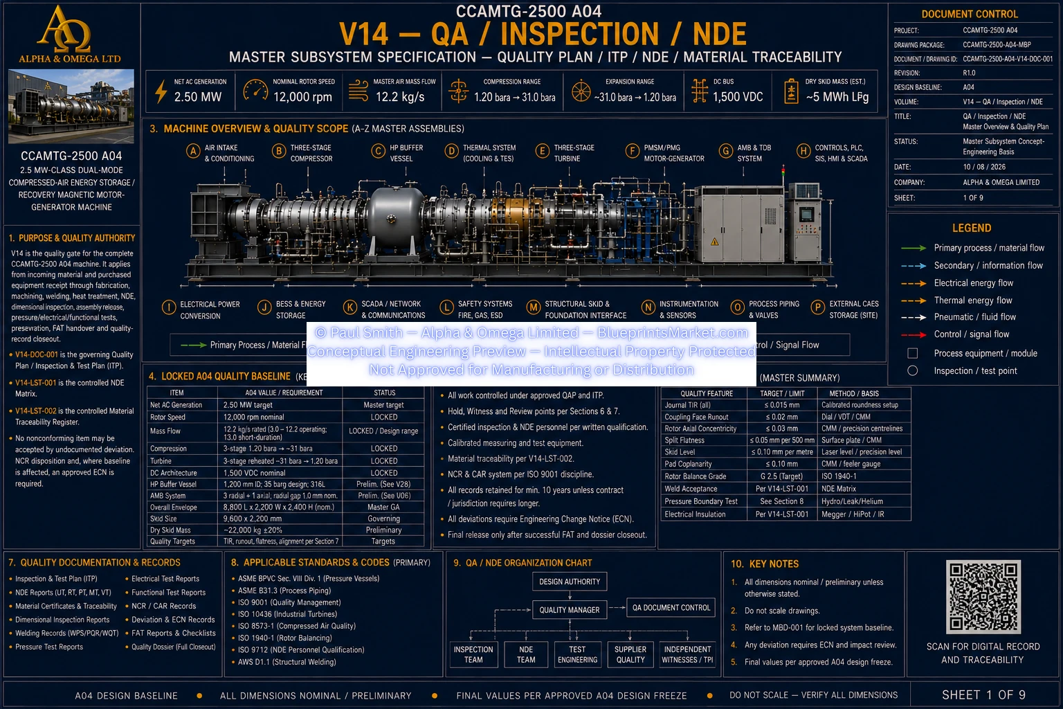
V14 QA Inspection NDE Sheet 1 of 9
© Paul Smith — Alpha & Omega Limited — PlatformClouds.com — Conceptual Engineering Preview — Not Approved for Manufacturing
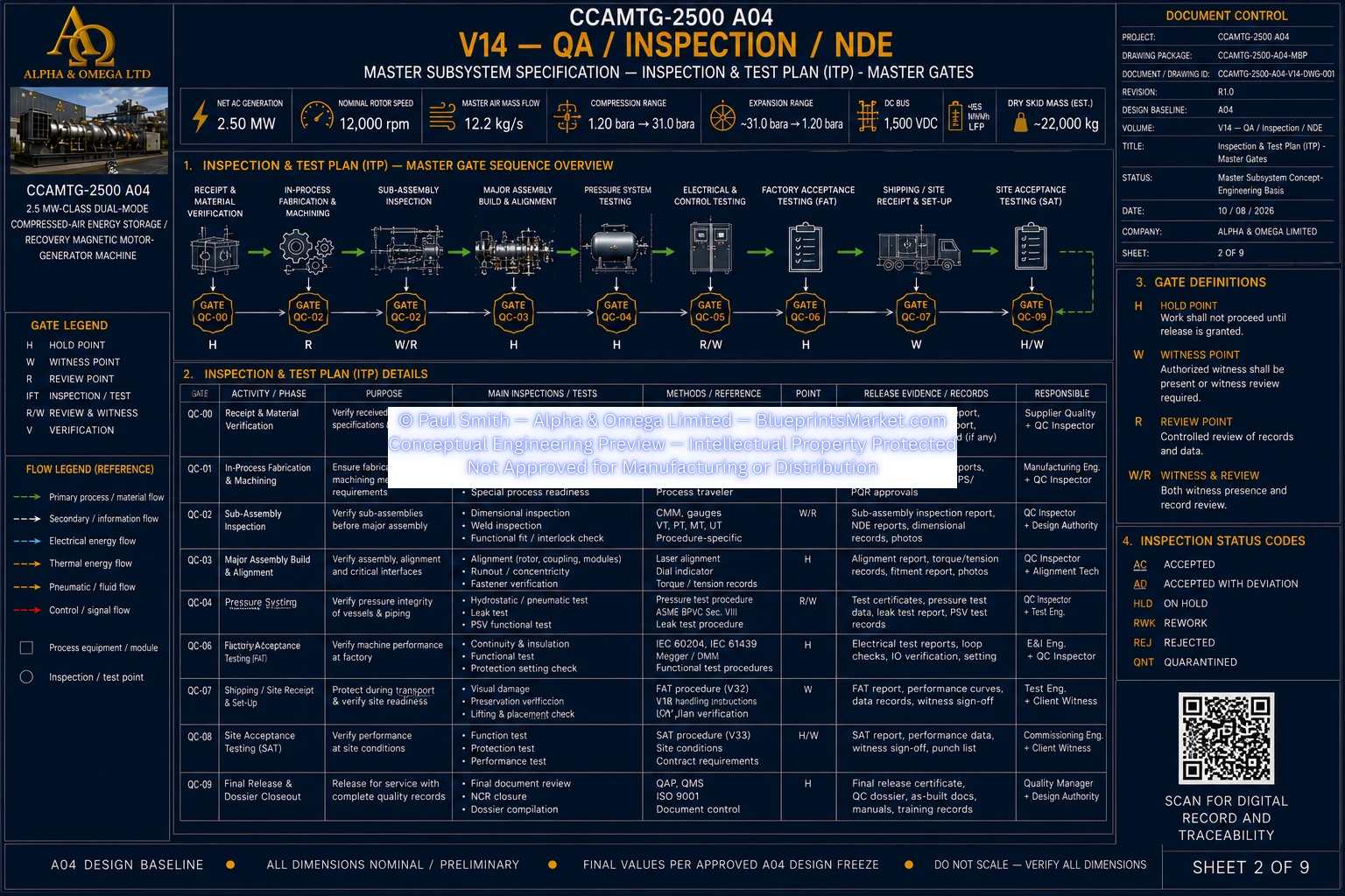
V14 QA Inspection NDE Sheet 2A of 9
© Paul Smith — Alpha & Omega Limited — PlatformClouds.com — Conceptual Engineering Preview — Not Approved for Manufacturing
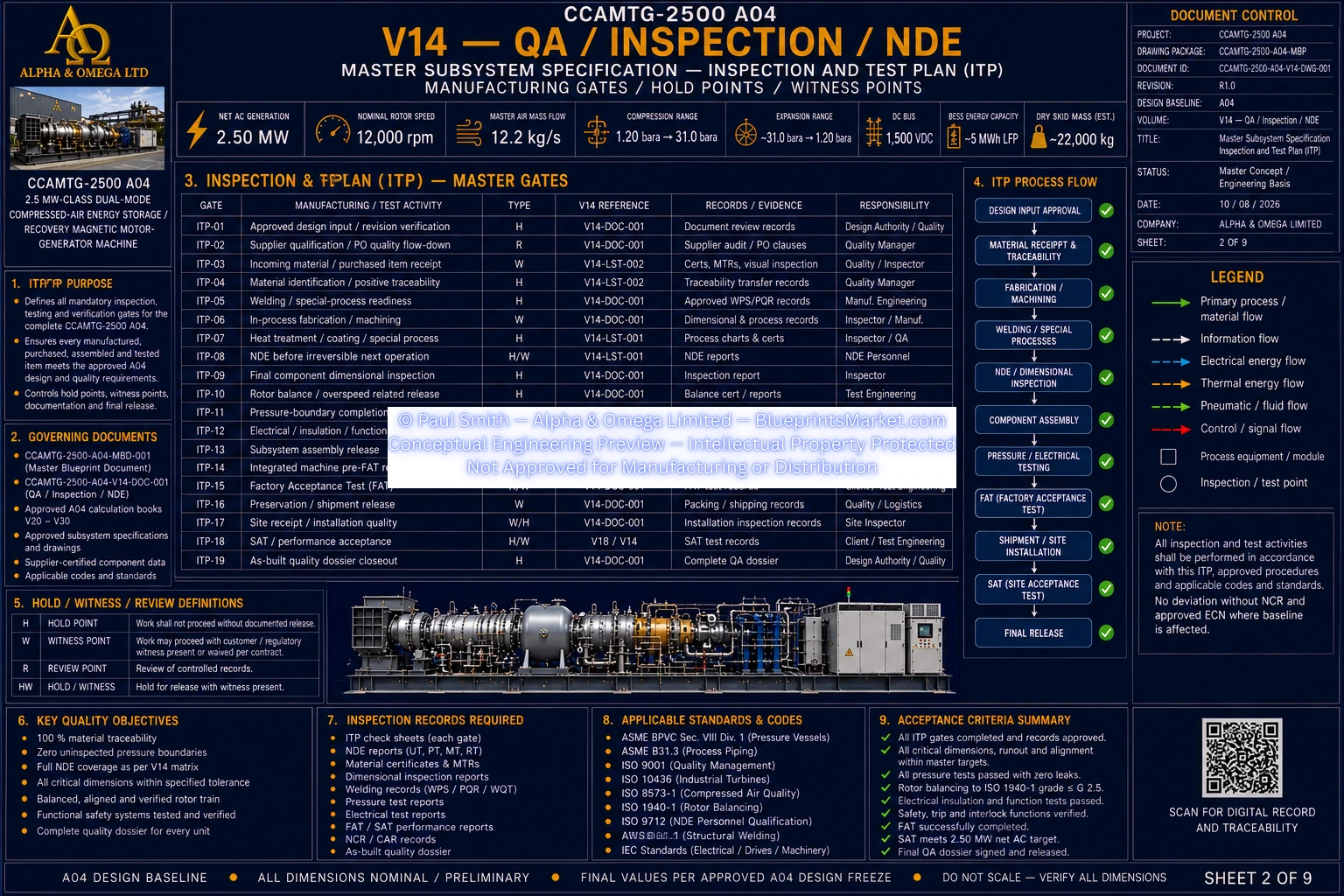
V14 QA Inspection NDE Sheet 2B of 9
© Paul Smith — Alpha & Omega Limited — PlatformClouds.com — Conceptual Engineering Preview — Not Approved for Manufacturing
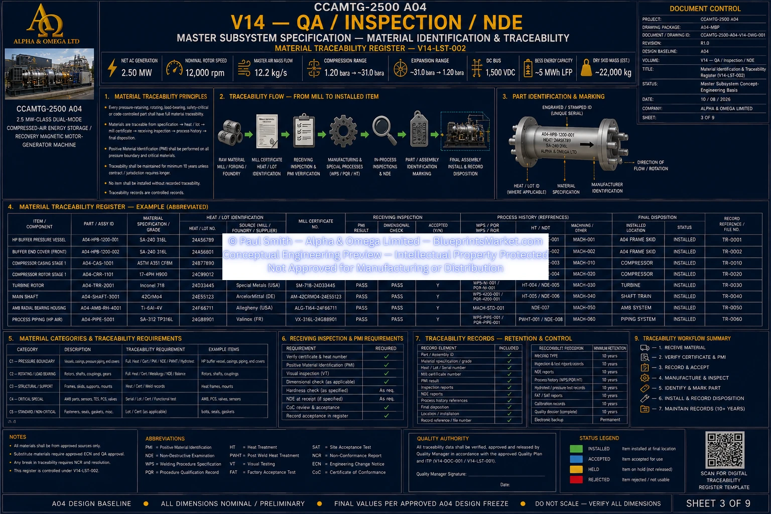
V14 QA Inspection NDE Sheet 3 of 9
© Paul Smith — Alpha & Omega Limited — PlatformClouds.com — Conceptual Engineering Preview — Not Approved for Manufacturing
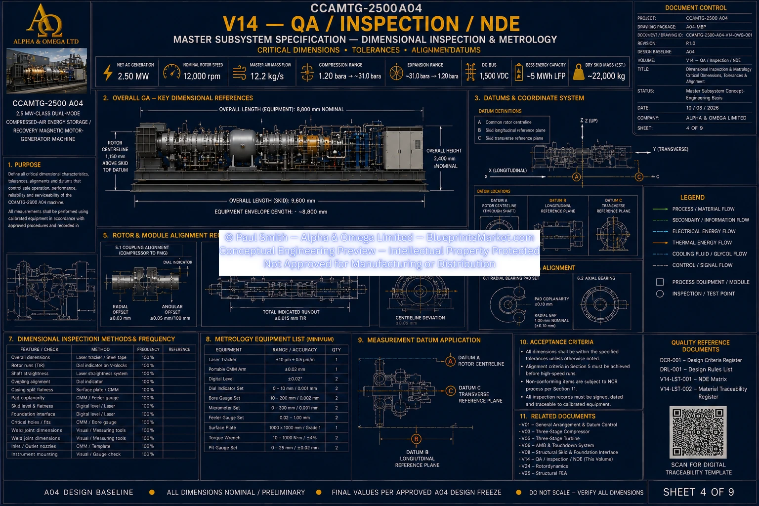
V14 QA Inspection NDE Sheet 4 of 9
© Paul Smith — Alpha & Omega Limited — PlatformClouds.com — Conceptual Engineering Preview — Not Approved for Manufacturing
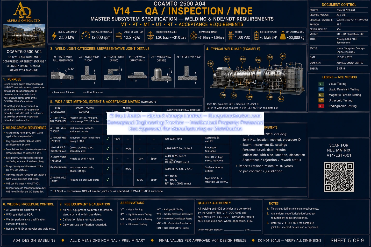
V14 QA Inspection NDE Sheet 5 of 9
© Paul Smith — Alpha & Omega Limited — PlatformClouds.com — Conceptual Engineering Preview — Not Approved for Manufacturing
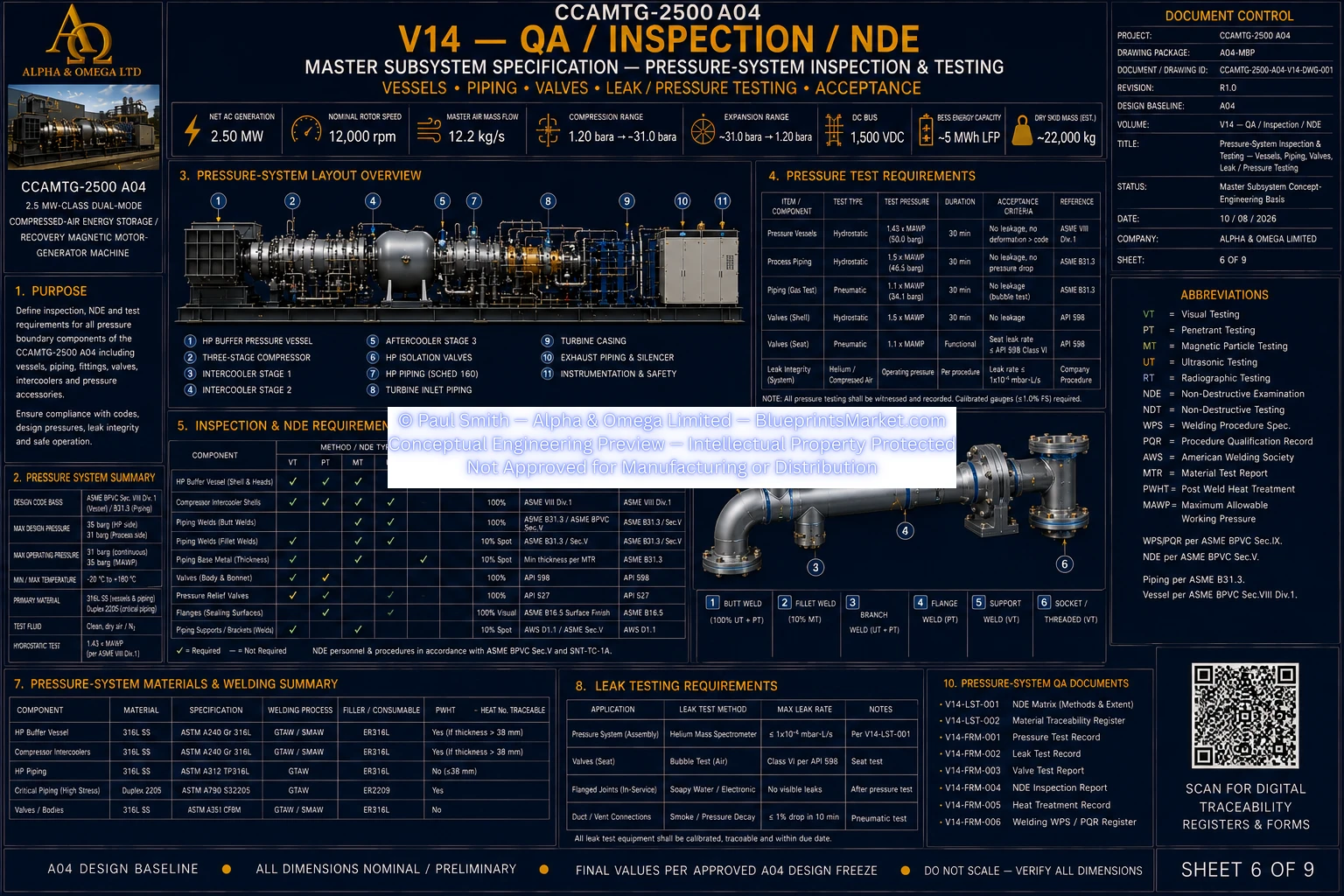
V14 QA Inspection NDE Sheet 6 of 9
© Paul Smith — Alpha & Omega Limited — PlatformClouds.com — Conceptual Engineering Preview — Not Approved for Manufacturing
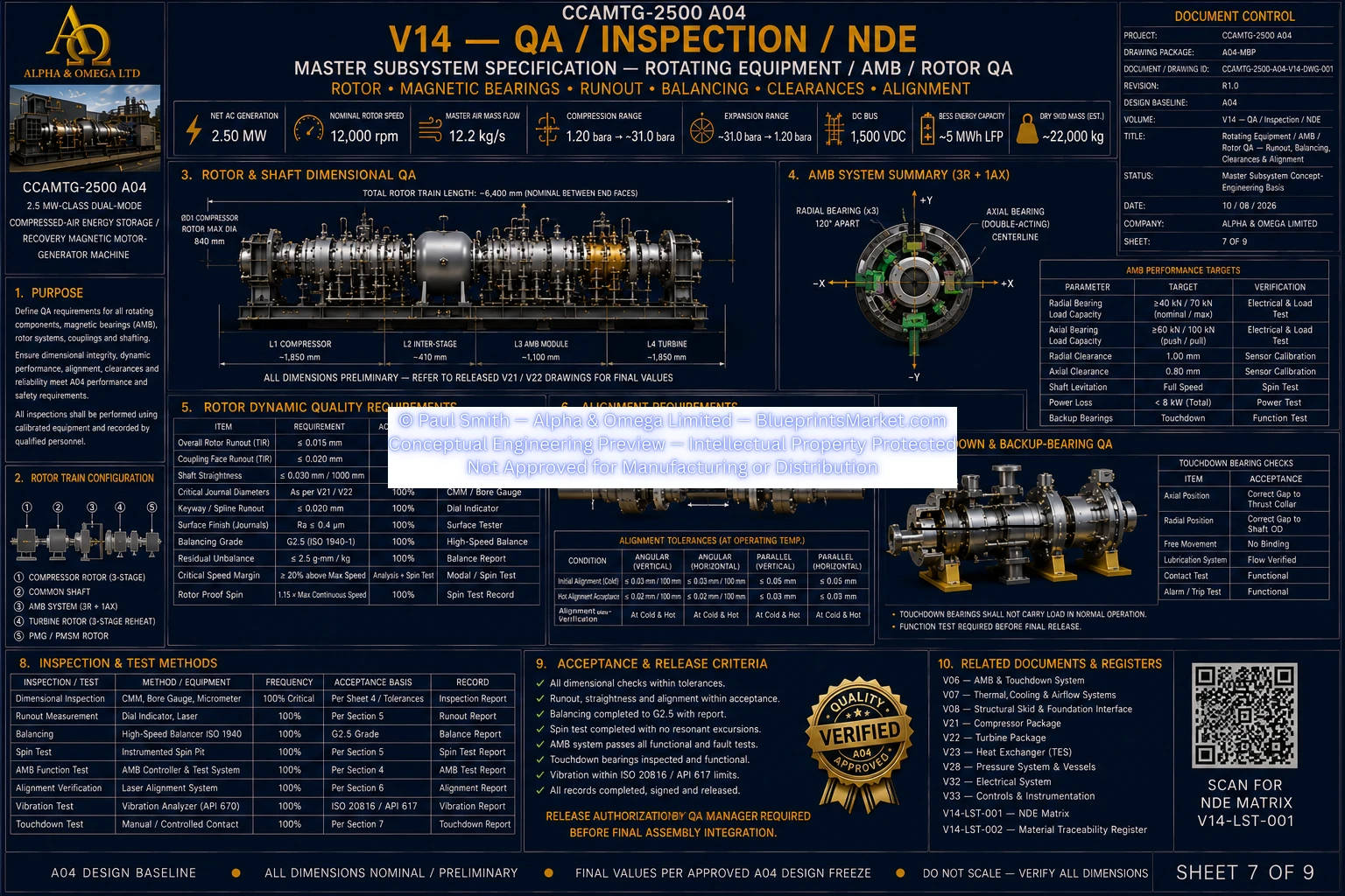
V14 QA Inspection NDE Sheet 7 of 9
© Paul Smith — Alpha & Omega Limited — PlatformClouds.com — Conceptual Engineering Preview — Not Approved for Manufacturing
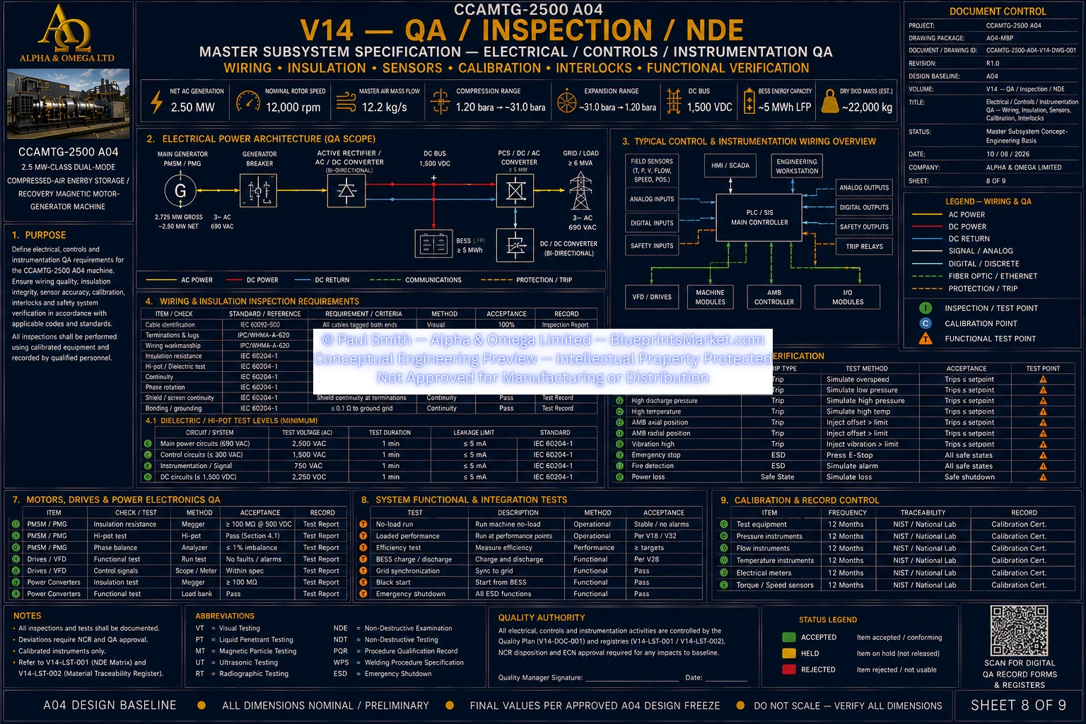
V14 QA Inspection NDE Sheet 8 of 9
© Paul Smith — Alpha & Omega Limited — PlatformClouds.com — Conceptual Engineering Preview — Not Approved for Manufacturing
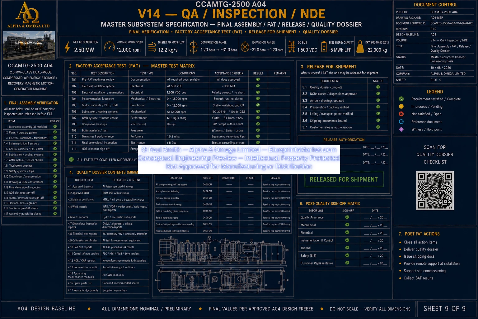
V14 QA Inspection NDE Sheet 9 of 9
© Paul Smith — Alpha & Omega Limited — PlatformClouds.com — Conceptual Engineering Preview — Not Approved for Manufacturing

V15 — Assembly & Installation

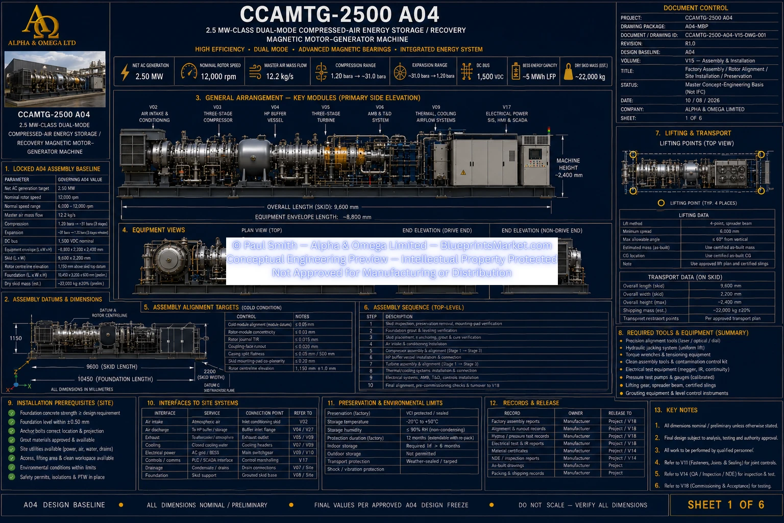
V15 Assembly Installation Sheet 1 of 6
© Paul Smith — Alpha & Omega Limited — PlatformClouds.com — Conceptual Engineering Preview — Not Approved for Manufacturing
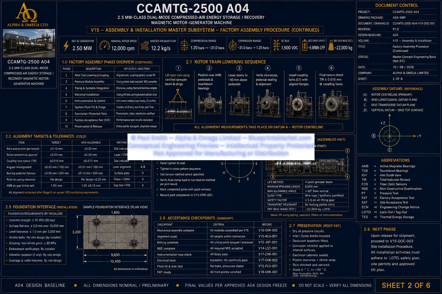
V15 Assembly Installation Sheet 2 of 6
© Paul Smith — Alpha & Omega Limited — PlatformClouds.com — Conceptual Engineering Preview — Not Approved for Manufacturing
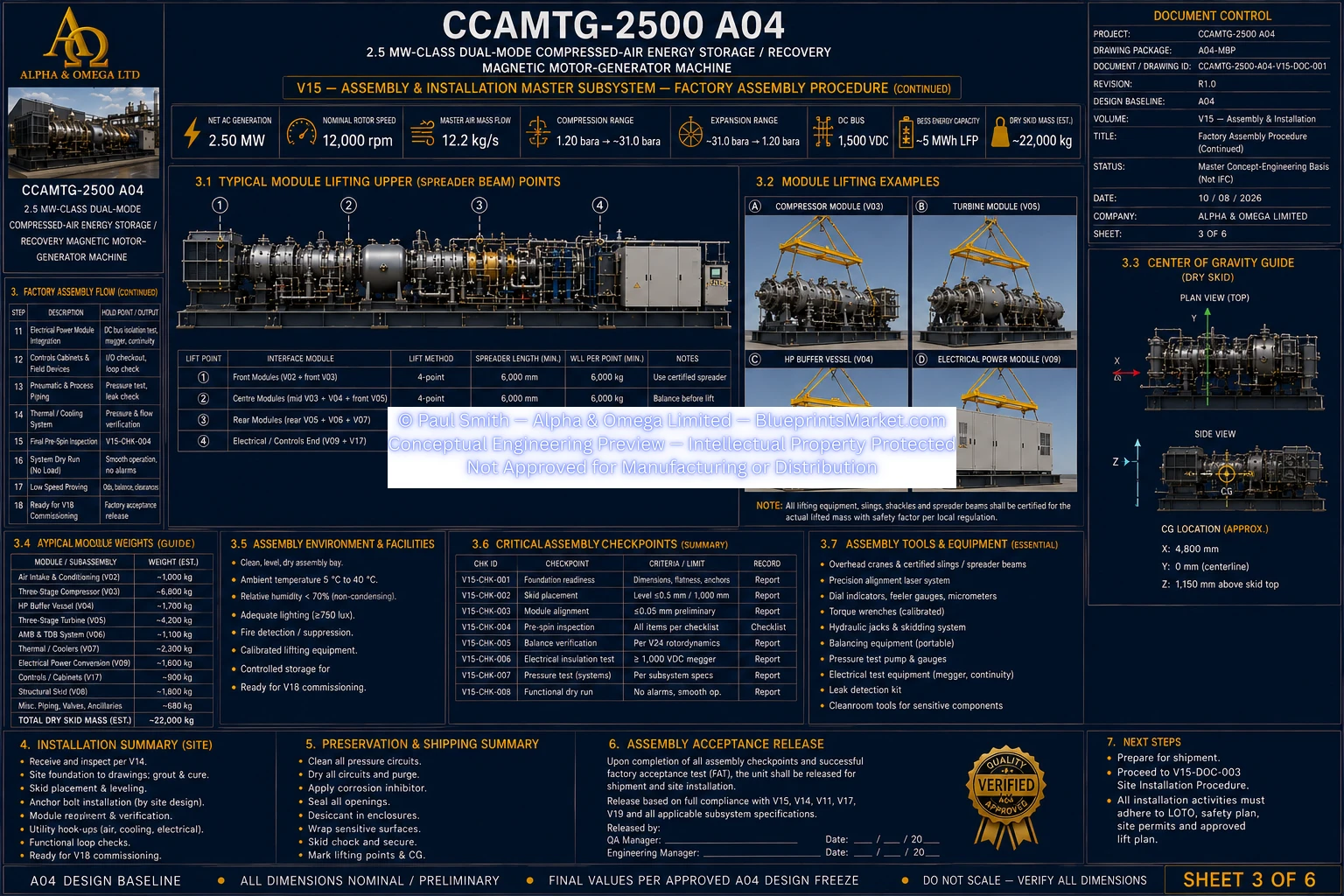
V15 Assembly Installation Sheet 3 of 6
© Paul Smith — Alpha & Omega Limited — PlatformClouds.com — Conceptual Engineering Preview — Not Approved for Manufacturing
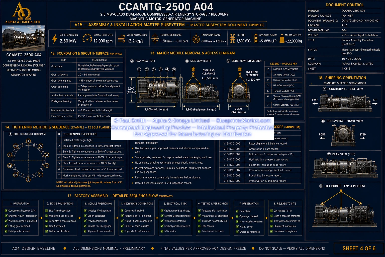
V15 Assembly Installation Sheet 4 of 6
© Paul Smith — Alpha & Omega Limited — PlatformClouds.com — Conceptual Engineering Preview — Not Approved for Manufacturing
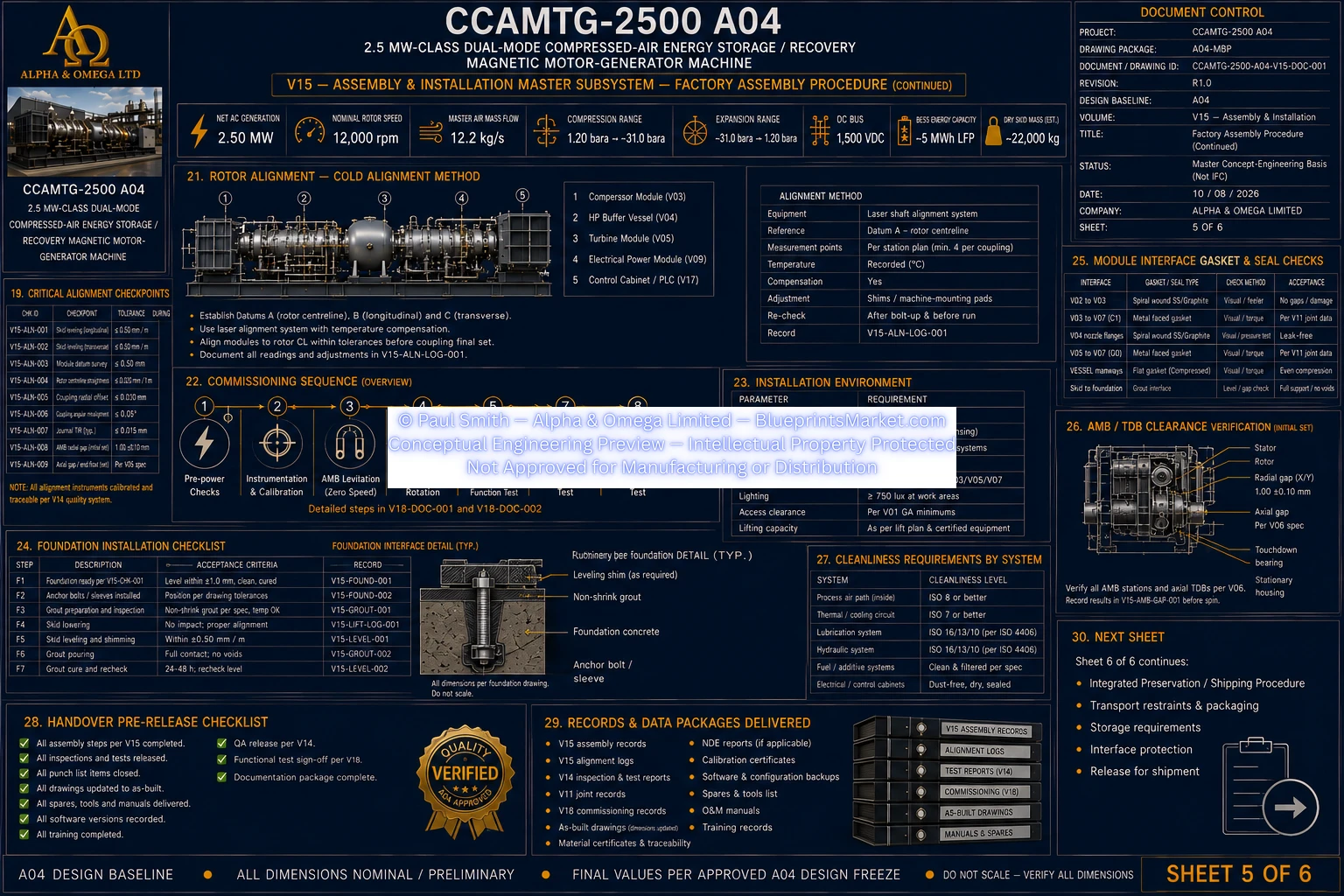
V15 Assembly Installation Sheet 5 of 6
© Paul Smith — Alpha & Omega Limited — PlatformClouds.com — Conceptual Engineering Preview — Not Approved for Manufacturing
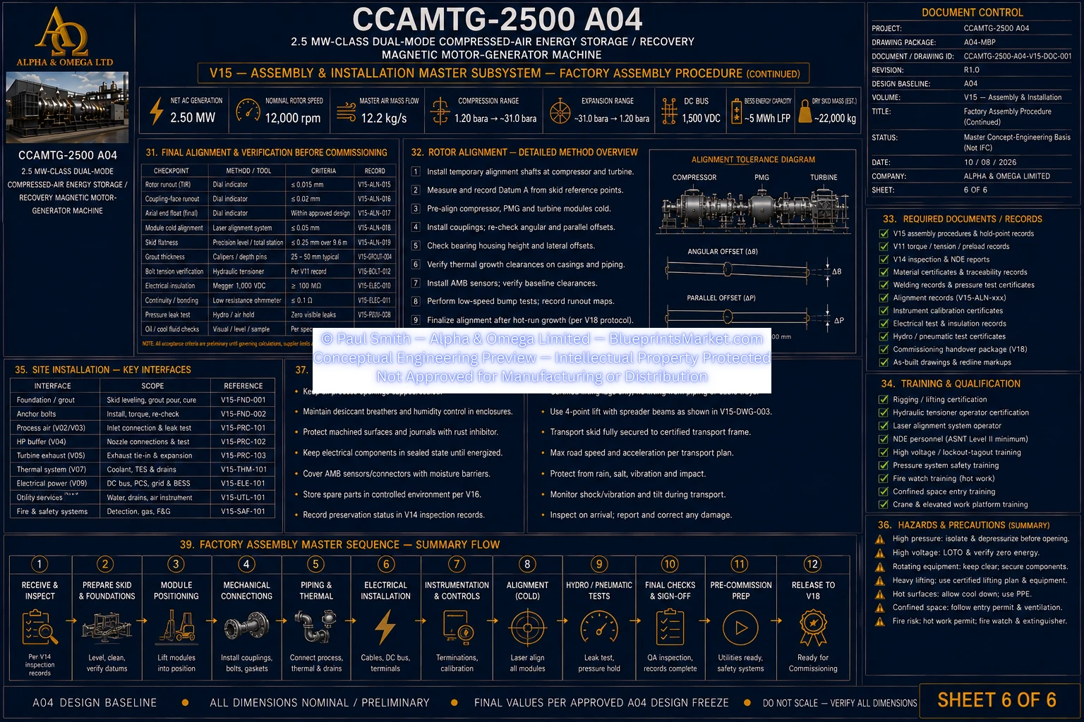
V15 Assembly Installation Sheet 6 of 6
© Paul Smith — Alpha & Omega Limited — PlatformClouds.com — Conceptual Engineering Preview — Not Approved for Manufacturing

V16 — Maintenance, Service & Lifecycle

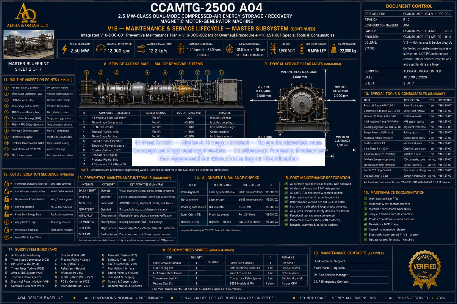
V16 Maintenance Service Lifecycle Sheet 2 of 7
© Paul Smith — Alpha & Omega Limited — PlatformClouds.com — Conceptual Engineering Preview — Not Approved for Manufacturing
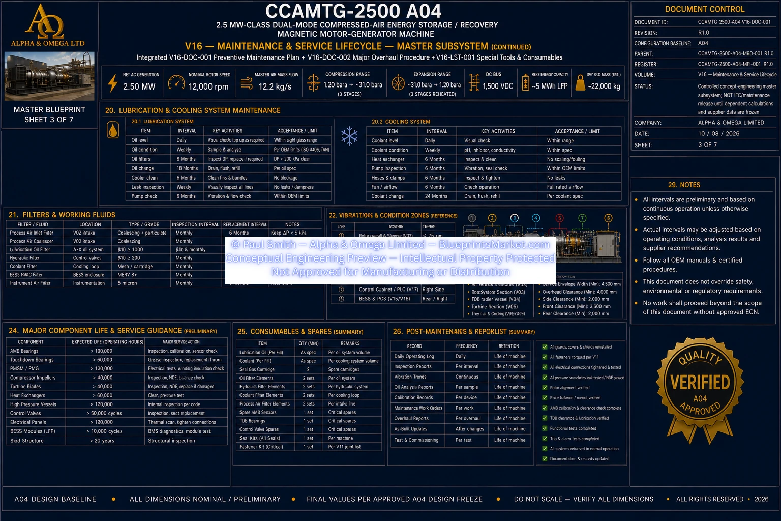
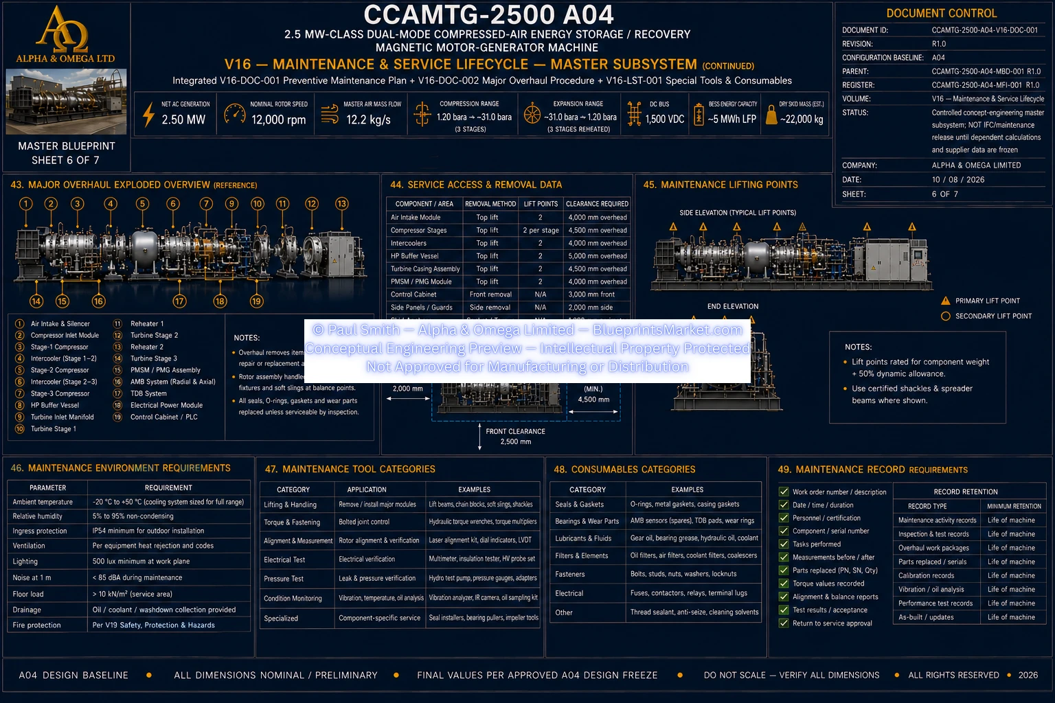
V16 Maintenance Service Lifecycle Sheet 3 of 7
© Paul Smith — Alpha & Omega Limited — PlatformClouds.com — Conceptual Engineering Preview — Not Approved for Manufacturing
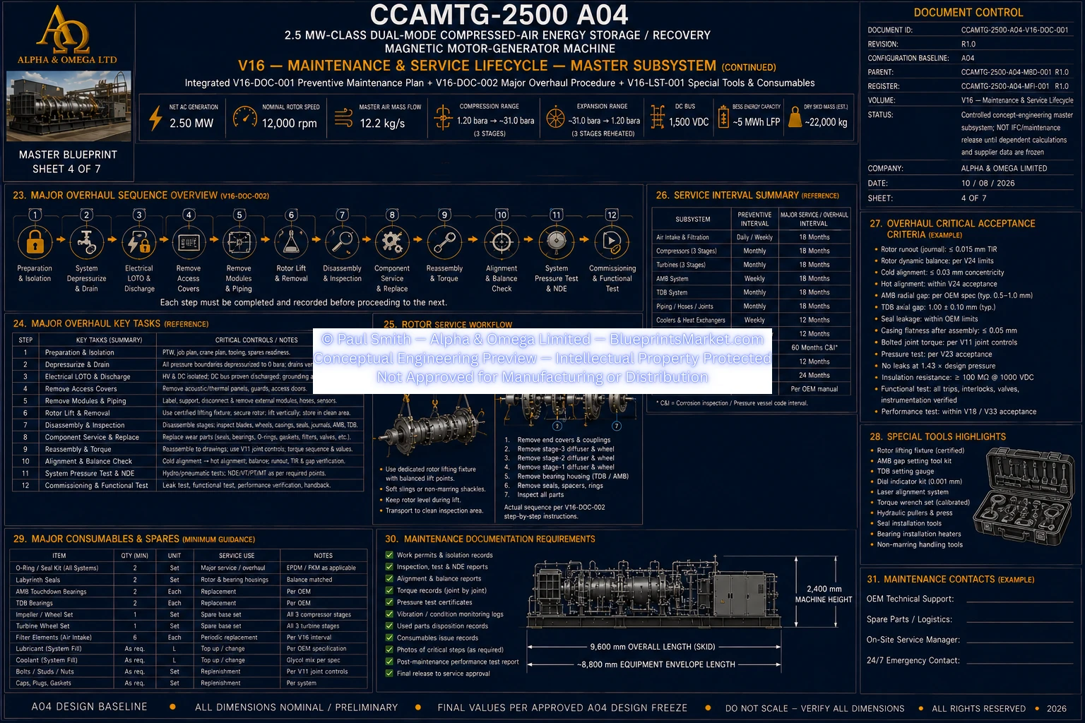
V16 Maintenance Service Lifecycle Sheet 4 of 7
© Paul Smith — Alpha & Omega Limited — PlatformClouds.com — Conceptual Engineering Preview — Not Approved for Manufacturing
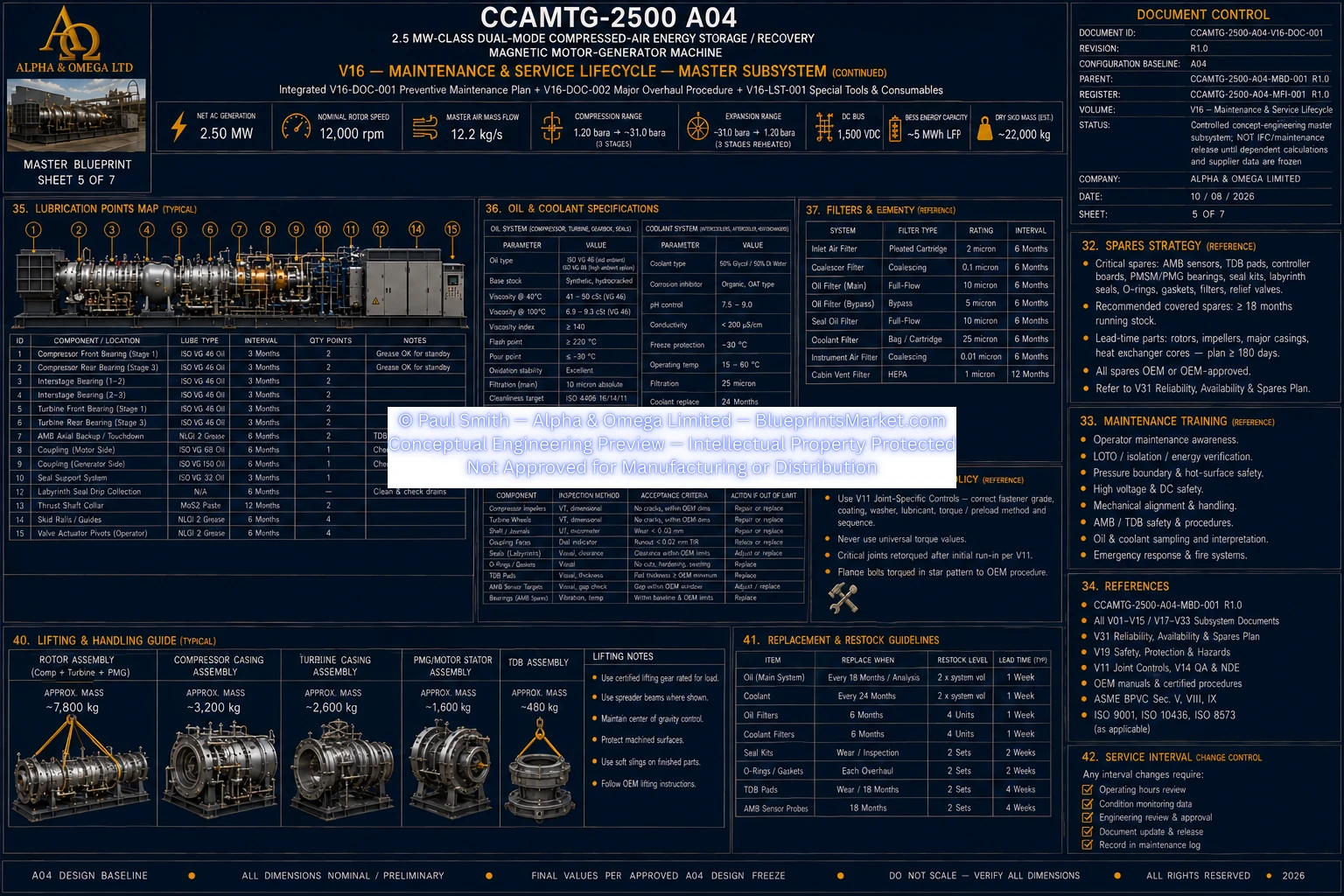
V16 Maintenance Service Lifecycle Sheet 5 of 7
© Paul Smith — Alpha & Omega Limited — PlatformClouds.com — Conceptual Engineering Preview — Not Approved for Manufacturing
V16 Maintenance Service Lifecycle Sheet 6 of 7
© Paul Smith — Alpha & Omega Limited — PlatformClouds.com — Conceptual Engineering Preview — Not Approved for Manufacturing
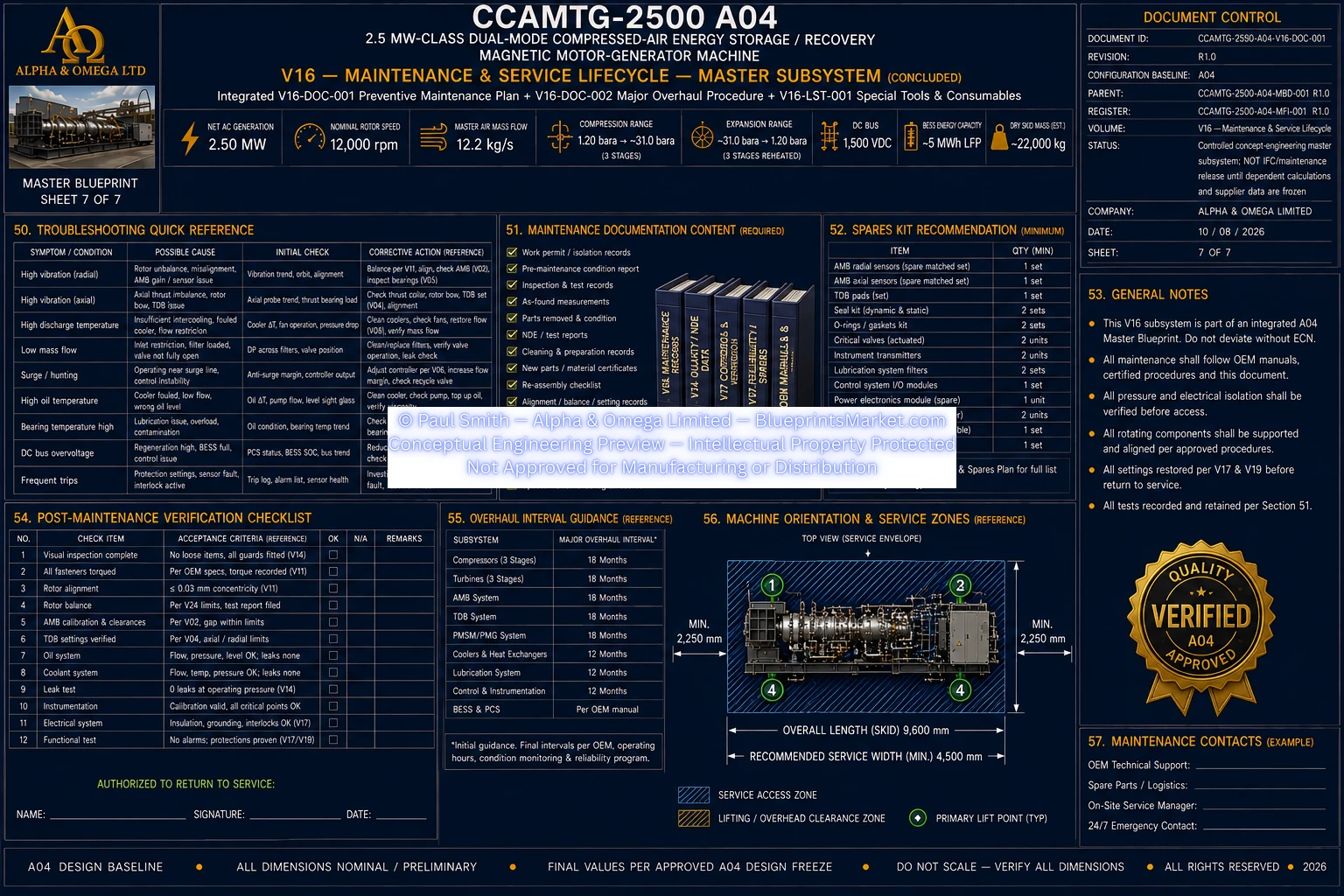
V16 Maintenance Service Lifecycle Sheet 7 of 7
© Paul Smith — Alpha & Omega Limited — PlatformClouds.com — Conceptual Engineering Preview — Not Approved for Manufacturing

V17 — Controls, PLC, SIS, HMI & SCADA

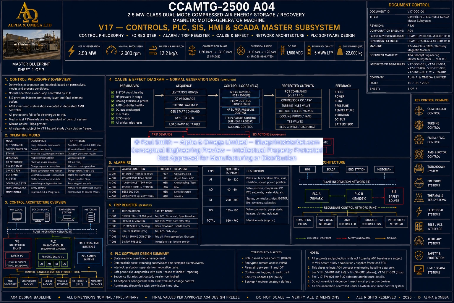
V17 Controls PLC SIS HMI SCADA Sheet 1 of 7
© Paul Smith — Alpha & Omega Limited — PlatformClouds.com — Conceptual Engineering Preview — Not Approved for Manufacturing
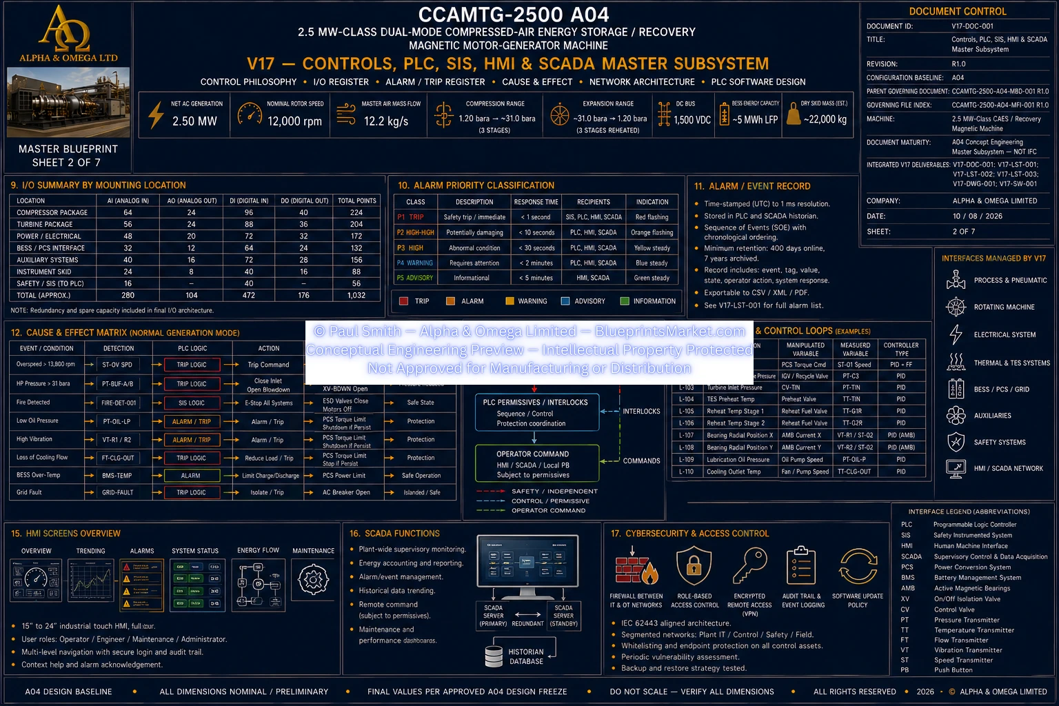
V17 Controls PLC SIS HMI SCADA Sheet 2 of 7
© Paul Smith — Alpha & Omega Limited — PlatformClouds.com — Conceptual Engineering Preview — Not Approved for Manufacturing
V17 Controls PLC SIS HMI SCADA Sheet 3 of 7
© Paul Smith — Alpha & Omega Limited — PlatformClouds.com — Conceptual Engineering Preview — Not Approved for Manufacturing
V17 Controls PLC SIS HMI SCADA Sheet 4 of 7
© Paul Smith — Alpha & Omega Limited — PlatformClouds.com — Conceptual Engineering Preview — Not Approved for Manufacturing
V17 Controls PLC SIS HMI SCADA Sheet 5 of 7
© Paul Smith — Alpha & Omega Limited — PlatformClouds.com — Conceptual Engineering Preview — Not Approved for Manufacturing
V17 Controls PLC SIS HMI SCADA Sheet 6 of 7
© Paul Smith — Alpha & Omega Limited — PlatformClouds.com — Conceptual Engineering Preview — Not Approved for Manufacturing
V17 Controls PLC SIS HMI SCADA Sheet 7 of 7
© Paul Smith — Alpha & Omega Limited — PlatformClouds.com — Conceptual Engineering Preview — Not Approved for Manufacturing