CCAMTG-2500 A04 — Assembly & Installation
Volume 15 defines the complete assembly and installation architecture for the CCAMTG-2500 A04,
covering controlled factory build, common-rotor alignment, subsystem installation, site placement,
foundation and grout interfaces, process and thermal hook-ups, electrical and controls integration,
preservation, lifting, transport, storage and final mechanical-completion handover.
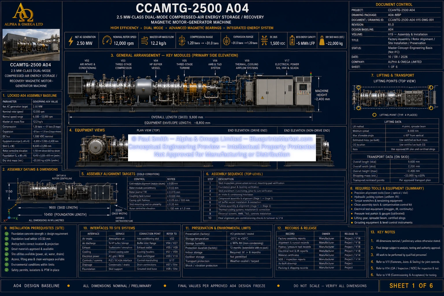
Main Public Assembly Baseline
- Machine Class: 2.5 MW-Class Dual-Mode Compressed-Air Energy Storage / Recovery Magnetic Motor-Generator Machine
- Net AC Generation: 2.50 MW
- Nominal Rotor Speed: 12,000 rpm
- Master Air Mass Flow: 12.2 kg/s
- Compression Range: 1.20 bara → ~31 bara
- Expansion Range: ~31 bara → 1.20 bara
- DC Bus: 1,500 VDC
- BESS Energy Capacity: ~5 MWh LFP
- Dry Skid Mass (Estimated): ~22,000 kg
A04 Assembly Status:
Public baseline values identify the current A04 machine configuration. Final assembly dimensions,
alignment tolerances, foundation details, anchor requirements and supplier-dependent clearances remain
controlled by their approved engineering calculations, released drawings and site-specific design.
Assembly & Installation Overview
- Factory machine assembly
- Common rotor alignment
- Compressor assembly and mounting
- PMSM/PMG installation
- Turbine assembly and mounting
- Active magnetic bearing installation
- Touchdown-bearing installation
- Thermal and cooling equipment installation
- HP buffer vessel installation
- Electrical and control integration
- Site installation and grouting
- Preservation, shipping and storage
Assembly Configuration Control
- Assembly follows the approved A04 configuration baseline
- Released subsystem drawings govern installed geometry
- Approved engineering changes are incorporated before irreversible assembly
- Manufactured and purchased components require QA release before installation
- Acceptance metrology uses calibrated and traceable equipment
- Pressure boundaries remain protected from contamination before closure
- Critical bolted joints use joint-specific controlled preload procedures
- Rotor handling uses certified tooling and protected surfaces
Primary Assembly Datums
- Common rotor centreline forms the principal rotating-machine datum
- Skid longitudinal reference controls machine positioning
- Skid transverse reference controls cross-machine positioning
- Compressor, PMSM/PMG and turbine sections align to the common rotor axis
- Bearing and casing centres reference the same controlled alignment system
- Final dimensional acceptance follows released drawings and analysis-frozen values
Factory Assembly Preparation
- Verify component identity and quantities
- Inspect incoming preservation and shipping condition
- Establish controlled clean assembly area
- Implement foreign-material-exclusion controls
- Verify calibrated assembly and metrology tooling
- Verify certified lifting fixtures
- Prepare protected rotor stands and handling equipment
- Establish assembly datums before machinery placement
Structural Skid Preparation
- Inspect primary skid datum surfaces
- Inspect machinery mounting pads
- Establish longitudinal and transverse reference datums
- Establish the common rotor reference axis
- Install controlled soleplates and chocks
- Preserve adjustment capability until rotor alignment is accepted
- Record support coordinates and elevations
Compressor Assembly
- Install compressor casing components in the released sequence
- Install three-stage diffuser architecture
- Install compressor impeller and rotor assemblies
- Install compressor labyrinth sealing systems
- Protect aerodynamic surfaces throughout assembly
- Verify component identity and orientation
- Inspect rotor and casing interfaces before closure
PMSM/PMG Assembly
- Install the motor-generator stator and housing
- Install the high-speed rotor module
- Protect permanent-magnet rotor-retention systems
- Protect electrical insulation systems
- Connect machine cooling interfaces
- Perform required insulation and continuity checks
- Record supplier and machine serial information
Turbine Assembly
- Install turbine rotor and wheel assemblies in controlled stage order
- Install nozzle guide vane assemblies
- Install turbine labyrinth sealing systems
- Install turbine casing and exhaust interfaces
- Protect released aerodynamic geometry from unapproved rework
- Verify wheel and guide-vane identity and orientation
- Inspect rotating and casing interfaces before closure
Active Magnetic Bearing Installation
- Install radial AMB stations concentric with the common rotor geometry
- Install the double-acting axial magnetic bearing
- Install radial rotor-position probes
- Install redundant axial position sensing
- Install rotor phase and speed sensing
- Verify sensor orientation and polarity
- Verify controller channel mapping
- Record final supplier-controlled bearing and sensing settings
Touchdown Bearing Installation
- Install independent touchdown support at each radial magnetic-bearing station
- Maintain separation between touchdown and normal non-contact support functions
- Verify mechanical support orientation
- Protect bearing surfaces during assembly
- Confirm monitoring functions before high-speed operation
- Final supplier-certified clearances and fault capabilities govern release
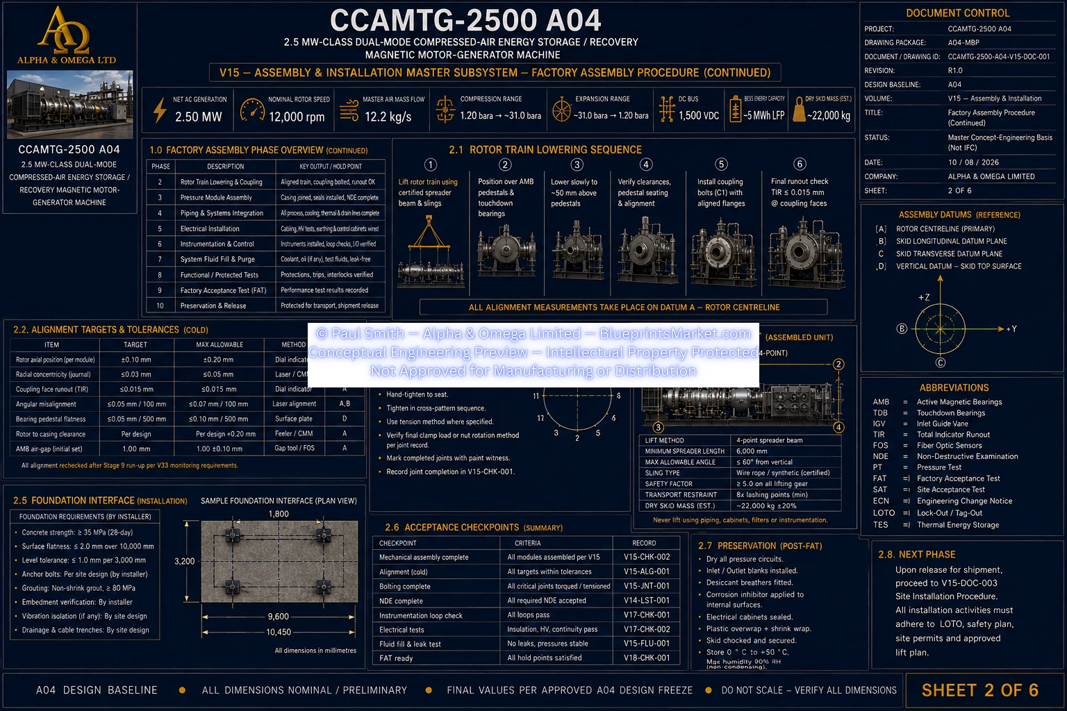
High-Speed Coupling Installation
- Install diaphragm couplings between rotor modules
- Establish preliminary axial positioning
- Verify coupling pilots and mating interfaces
- Inspect coupling-face condition and runout
- Do not perform final coupling closure before alignment acceptance
- Apply final joint preload only after approved rotor alignment
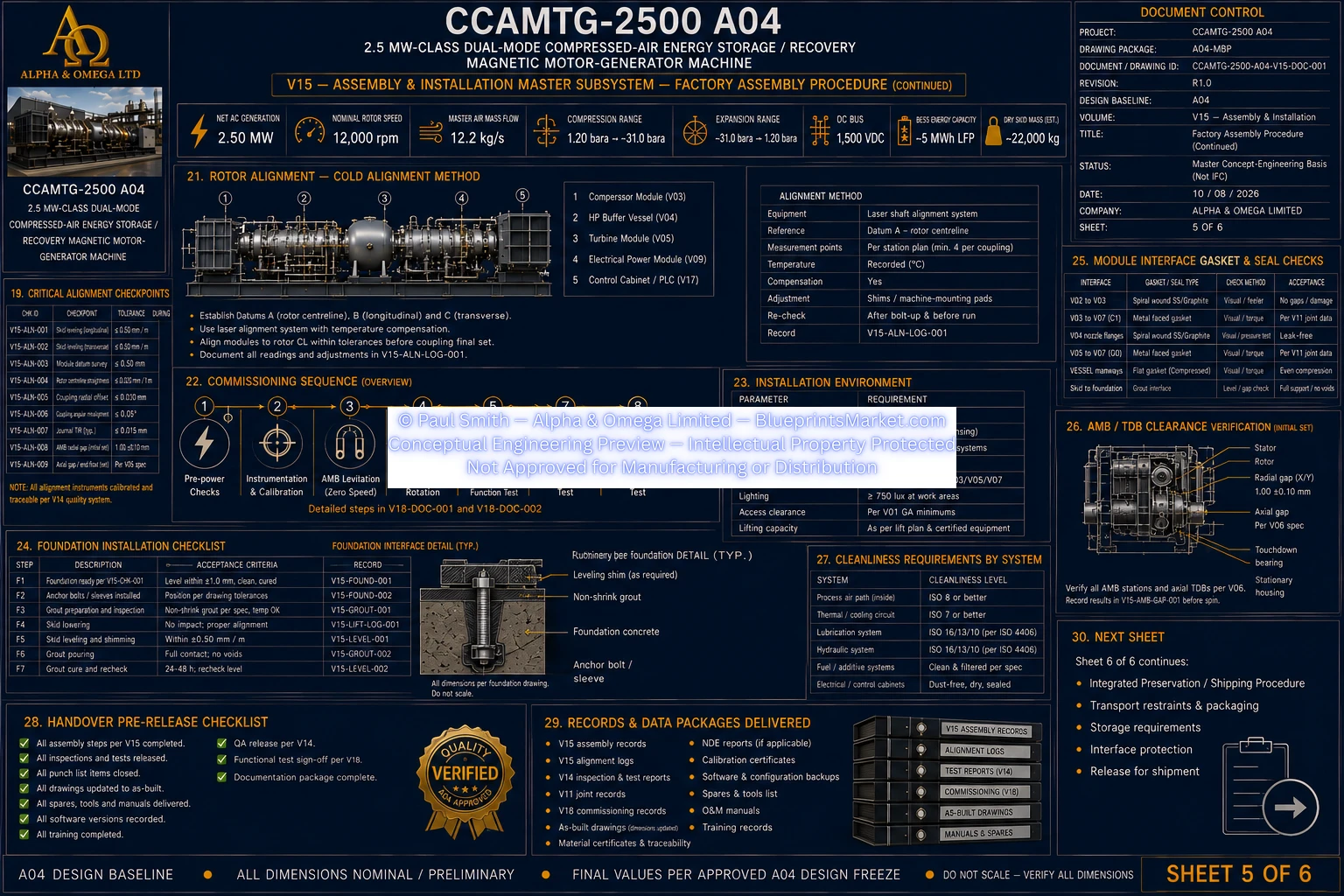
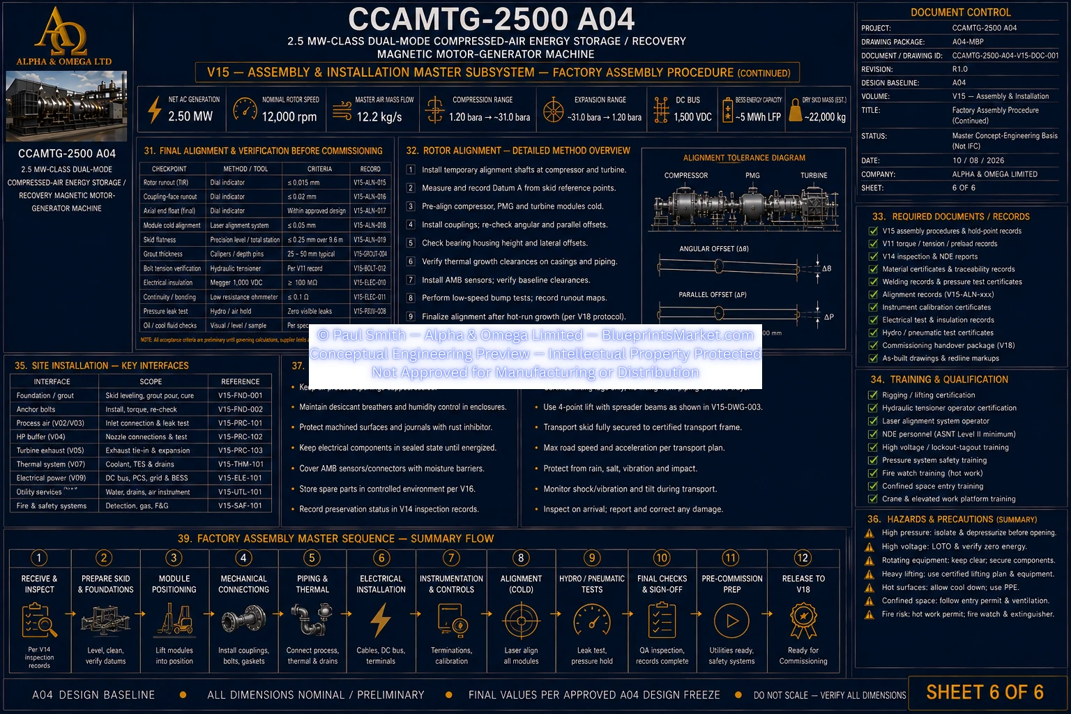
Rotor Alignment Procedure
- Alignment performed as a controlled metrology process
- Common rotor datum established from approved machine geometry
- Bearing, motor-generator and casing centres measured to the same reference
- Rotor journal and coupling interfaces inspected before alignment
- Horizontal and vertical coupling alignment measured using approved metrology
- Machinery adjusted using engineered chocks, soleplates and shims
- Process piping is never used to pull machinery into alignment
- Final alignment is rechecked after critical joint preload
Thermal Growth & Hot Alignment
- Cold assembly alignment can include approved intentional offsets
- Thermal expansion is incorporated into the alignment model
- Magnetic-bearing operating position is included in final alignment engineering
- Process and cooling piping effects are checked after connection
- Electrical and thermal hook-ups are checked for installation-induced movement
- Operating shaft position and thermal growth are verified during commissioning
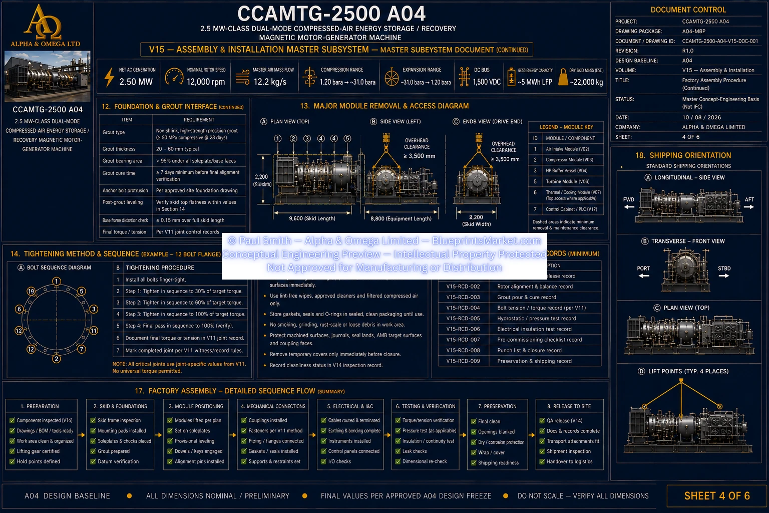
Critical Joint Assembly
- Machinery mounting joints use controlled installation methods
- Casing joints use released gasket and seal procedures
- Coupling joints use calculated joint preload
- Critical fasteners are installed and inspected individually
- Locking systems are verified after tightening
- Assembly records preserve joint identity and final installation status
Air Intake & Compressor Process Installation
- Install air intake and filtration equipment
- Install inlet guide vane hardware
- Install compressor discharge collection system
- Install protective anti-surge recycle equipment
- Verify process flow direction
- Verify valve fail-safe orientation
- Verify actuator and instrumentation orientation
Thermal & Cooling Installation
- Install compressor intercoolers
- Install aftercooler and heat-recovery equipment
- Install turbine preheater
- Install turbine interstage reheaters
- Install the closed machine-cooling package
- Connect controlled drains and vents
- Install thermal instrumentation
- Preserve thermal expansion and equipment serviceability
HP Buffer Vessel Installation
- Install the HP buffer vessel on its approved support interface
- Verify vessel support alignment
- Control process nozzle loads
- Install independent pressure-relief protection
- Install controlled drain and depressurization interfaces
- Install pressure and temperature instrumentation
- Preserve access to inspection and maintenance locations
Pressure-Boundary Hook-Up
- Maintain correct process-flow direction
- Maintain correct pressure and temperature service classification
- Install fail-safe high-pressure isolation
- Maintain protective compressor recycle functionality
- Preserve independent mechanical overpressure protection
- Do not allow temporary shipping or commissioning items to defeat relief paths
- Support piping independently of rotating machinery
- Recheck rotor alignment after final pressure-system hook-up
Electrical Installation
- Install electrical conversion enclosures
- Install active rectifier and inverter equipment
- Install common DC power-system equipment
- Install magnetic-bearing amplifiers and controllers
- Install PLC, SIS, HMI and SCADA equipment
- Implement approved electrical isolation and precharge architecture
- Verify polarity and insulation
- Install touch-safe barriers and required protective interfaces
Cabling & Instrumentation Installation
- Route power cables through approved pathways
- Segregate power, control, instrumentation and network cabling
- Maintain required cable support and bend radius
- Install shielding and earthing correctly
- Install uniquely tagged pressure, temperature and flow instruments
- Install rotor-position, vibration and speed sensors
- Verify cable continuity and polarity
- Verify instrumentation calibration records
Earthing & Bonding Installation
- Bond the machine structure
- Bond the structural skid
- Bond electrical enclosures
- Bond cable trays
- Bond guards and exposed conductive components
- Verify continuity before electrical energization
- Record final earthing and bonding inspection results
Machine Guards & Access Systems
- Install rotating-equipment guards
- Install hot-surface insulation and protection
- Install equipment labels and safety markings
- Install access panels
- Preserve valve and instrumentation access
- Preserve maintenance-removal envelopes
- Ensure guards do not interfere with approved lifting interfaces
Pre-Rotation Mechanical Checks
- Perform approved static rotation and clearance checks
- Verify there is no unintended rotor contact
- Verify magnetic-bearing levitation functionality
- Verify rotor centring
- Verify touchdown-bearing monitoring
- Zero and verify rotor-position sensing
- Establish baseline vibration and probe readings
Site Readiness
- Verify installation permits and method statements
- Verify lifting and access routes
- Verify utilities and laydown areas
- Verify environmental installation conditions
- Survey foundation position and elevation
- Inspect foundation condition before machinery placement
- Verify site-specific anchor and structural design
Foundation & Grout Interface
- Prepare machinery foundation surfaces
- Install approved leveling systems
- Set the skid to controlled survey datums
- Establish the rotor centreline reference before grouting
- Install anchors only to the approved site structural design
- Use approved high-strength non-shrink machinery grout
- Verify grout placement and curing before final load transfer
- Recheck rotor alignment after foundation load transfer
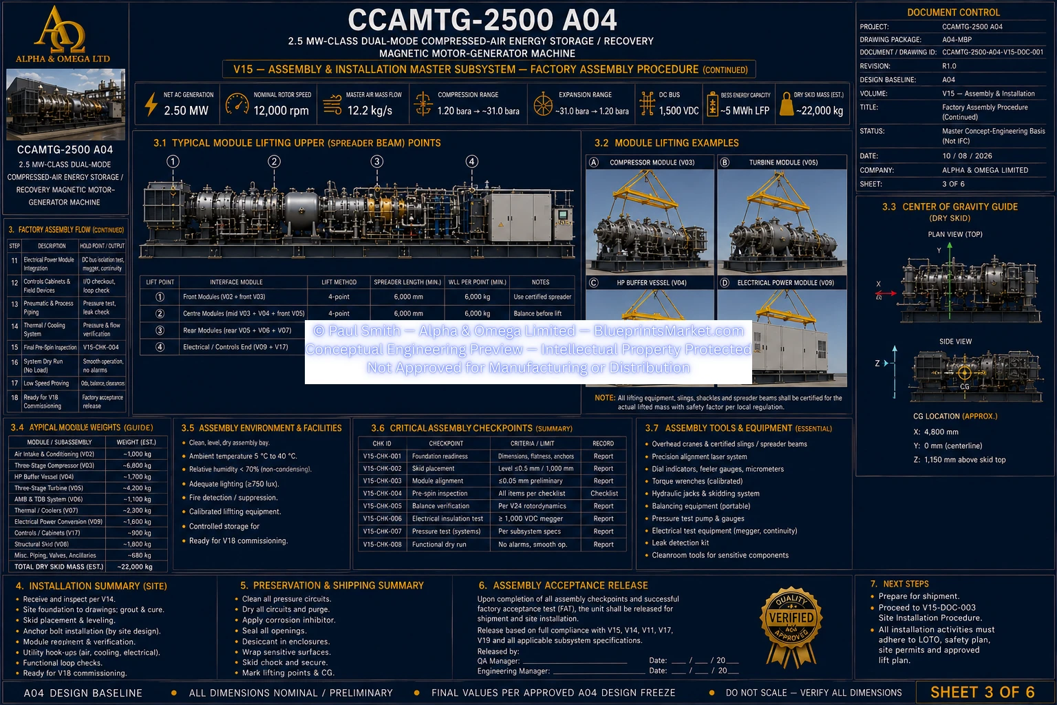
Machine Positioning & Lifting
- Use only certified machine lifting points
- Use current as-built shipping mass and centre-of-gravity data
- Use approved lift calculations and rigging geometry
- Do not lift from process nozzles or rotating-equipment casings
- Do not lift from magnetic-bearing housings, piping, guards or cable trays
- Protect the common rotor train from handling shock
- Maintain controlled lifting exclusion zones
External System Hook-Ups
- External compressed-air storage interface
- Air intake and exhaust interface
- Thermal-energy storage interface
- Machine cooling interface
- Drain and vent systems
- Grid, transformer and PCS interfaces
- Battery energy storage interface
- Controls and communications interfaces
Cooling & Thermal Circuit Completion
- Flush and clean thermal circuits
- Flush and clean cooling circuits
- Use approved working fluids
- Vent circuits before operation
- Perform leak checks
- Verify filter installation direction
- Verify chemistry and cleanliness requirements before operation
Preservation & Shipping
- Close quality-release requirements before preservation
- Clean and dry internal cavities
- Protect precision-machined surfaces
- Protect electrical and electronic enclosures
- Protect process openings with controlled covers
- Install approved rotor shipping restraints
- Apply transport-appropriate weather protection
- Use transport-condition indicators where required
Transport Controls
- Transport restraints use approved structural attachment points
- Machine is secured against longitudinal, lateral and vertical transport loads
- No tie-down through process nozzles or unapproved casings
- Rotor and precision interfaces are protected from shock
- Transport events outside approved limits trigger engineering inspection
- Alignment and runout checks may be repeated after abnormal transport events
Storage Controls
- Store the machine in a level and secure location
- Maintain a dry controlled environment
- Inspect preservation status periodically
- Monitor humidity and desiccant condition
- Renew preservation systems at approved intervals
- Follow supplier requirements for motor-generator and magnetic-bearing systems
- Manage battery systems separately under the approved BESS supplier requirements
Foreign Material Exclusion
- Maintain controlled logs for temporary items entering machine cavities
- Account for temporary plugs and caps
- Account for loose tools and fasteners
- Account for cleaning materials and desiccant bags
- Maintain process-air paths clean and dry
- Prevent machining debris and weld contamination
- Control stainless-steel contamination
- Ensure temporary blinds do not defeat safety or relief functions
Assembly Hold Points
- Incoming components accepted before assembly
- Skid datums accepted before machinery placement
- Rotor modules accepted before casing closure
- AMB, TDB and probes accepted before coupling closure
- Rotor alignment accepted before final mount and coupling preload
- Critical joint preload complete before concealment
- Pressure boundaries verified before insulation or guarding
- Electrical installation verified before energization
- Factory mechanical completion verified before FAT
- Foundation and anchors accepted before site machine placement
- Grout accepted before final structural load transfer
- Final site alignment accepted after all major hook-ups
Assembly & Installation Records
- Component serial and material traceability
- Skid and foundation surveys
- Chock and shim records
- Grout and anchor records
- Rotor alignment records
- Critical joint preload records
- Pressure-boundary and leak-test records
- Cable and earthing records
- Instrumentation calibration records
- Foreign-material-exclusion closure records
- Lifting, transport and preservation records
- NCR, repair and engineering-change records
- Final redlined and as-built configuration records
Mechanical Completion
- Final assembly inspection completed
- All required guards installed
- Safety-critical punch items closed
- Temporary items accounted for
- Pressure-relief paths confirmed available
- Rotor rub and alignment issues resolved
- Magnetic-bearing sensing verified
- Earthing and bonding verified
- Machine handed over under controlled commissioning procedures
Commissioning Interface
- V15 ends at controlled mechanical and electrical completion
- First energized operation occurs under the commissioning procedures
- First pressurization occurs under controlled commissioning procedures
- First high-speed rotation occurs under controlled commissioning procedures
- Startup permissives verify emergency-stop health
- Cooling and magnetic-bearing systems must be available
- Electrical precharge and source availability must be proven
- Valve states and safety-trip systems must be verified before operation
Safety-Critical Installation Functions
- Independent mechanical overpressure protection
- Fail-safe high-pressure isolation
- Protective compressor anti-surge recycle
- Redundant speed protection
- Active magnetic bearing fault management
- Fire-protection integration
- Electrical insulation and earthing protection
- Machine guarding
- Controlled depressurization
- Safe rotor coast-down provisions
V15 Controlled Procedure Set
- Factory Assembly Procedure
- Rotor Alignment Procedure
- Site Installation Procedure
- Preservation / Shipping Procedure
- Assembly travelers and hold-point releases
- Alignment survey and as-found / as-left records
- Foundation, anchor and grout installation records
- Preservation and transport-release records
- Mechanical-completion and turnover dossier
Assembly & Installation Release Philosophy
- All mechanically coupled rotor sections remain on the common rotor centreline
- Every pressure boundary retains its approved material, service and relief architecture
- Every critical bolted joint uses calculated preload and controlled installation
- Every acceptance measurement records the governing datum and calibrated instrument
- No safety-critical NCR may remain open at release
- No temporary item may remain unaccounted for
- No pressure-relief path may be defeated
- No unresolved rotor rub, alignment or magnetic-bearing issue is permitted at handover
- Final installed values come only from approved drawings, analyses, supplier data and site-specific engineering