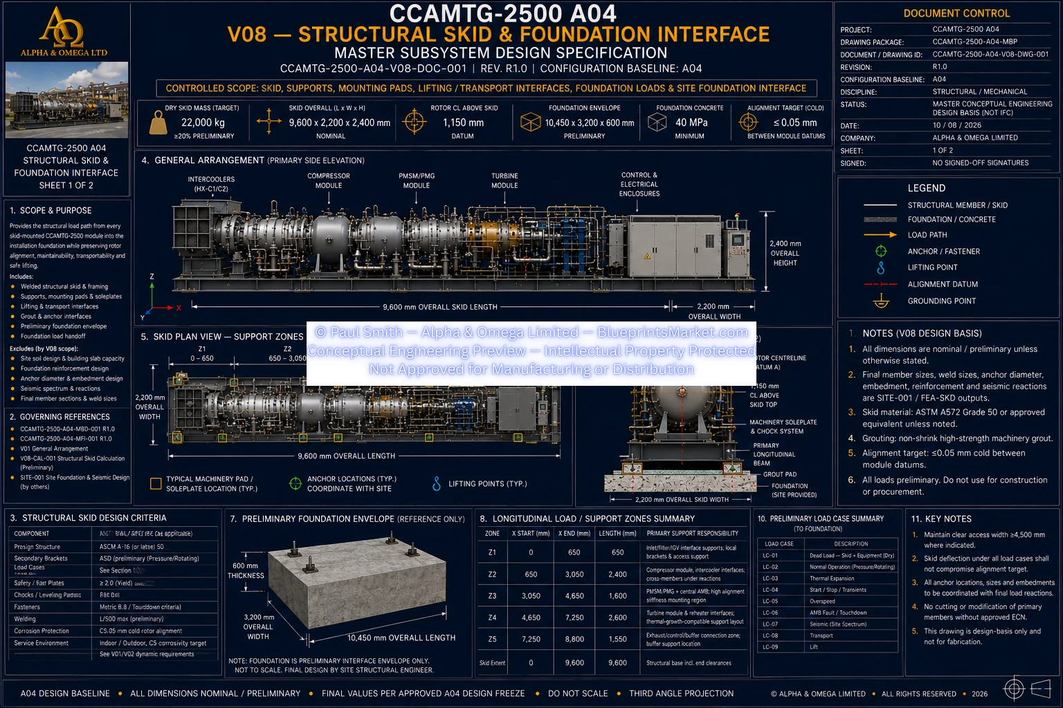
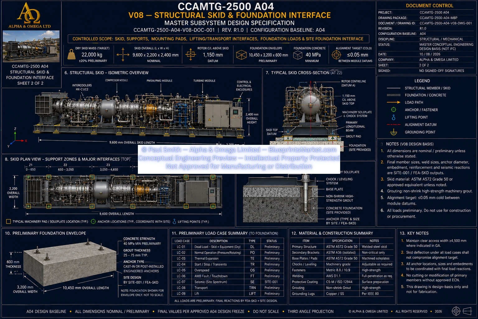
CCAMTG-2500 A04 — Structural Skid & Foundation Interface
Volume 08 defines the structural skid and foundation interface for the CCAMTG-2500 A04, providing the
structural load path from the skid-mounted machine assemblies into the installation foundation while
preserving rotor alignment, maintainability, transportability and safe lifting. The subsystem integrates
the primary structural frame, cross-members, machinery mounting interfaces, soleplates and chocks,
equipment support zones, lifting and transport provisions, grout and anchor interfaces, grounding and
bonding attachment provisions, structural load transfer and the site foundation interface.
Structural Skid System Overview
- Welded primary structural skid assembly
- Continuous longitudinal structural load paths
- Structural cross-members at concentrated machinery reactions
- Local diaphragms, doublers and gussets
- Machinery mounting pads
- Machined soleplates and chock system
- Equipment support brackets and structural interfaces
- Lifting and transport attachment interfaces
- Anchor and base interface system
- Non-shrink machinery grout interface
- Grounding and bonding attachment provisions
- Site foundation structural interface
Primary Structural Frame
- Primary frame based on continuous or fabricated longitudinal load paths
- Cross-members positioned beneath major machinery and structural reaction locations
- Structural reinforcement provided at concentrated load-transfer regions
- Vertical, lateral, longitudinal and torsional loads transferred into the primary frame
- Local reinforcement used where required to control yielding, buckling and distortion
- Primary structural openings subject to engineering analysis before release
- Secondary brackets separated from critical alignment and primary load paths where applicable
- Primary structure designed as an integrated machine-alignment structure rather than a simple support frame
Structural Material Architecture
- Primary skid structure based on ASTM A572 Grade 50 or approved equivalent
- Secondary non-critical brackets may use ASTM A36 where specifically approved
- Machined soleplates and chocks use qualified machinery-grade steel
- Structural fasteners use high-strength controlled fastening systems
- Weld consumables matched to the qualified base-metal and welding system
- Industrial corrosion-protection system selected for the installation environment
- Machined, grout and electrical bonding surfaces protected according to their functional requirements
Machinery Mounting System
- Machined machinery mounting-pad architecture
- Machined chock and soleplate system
- Alignment-controlled equipment support surfaces
- High-strength machinery hold-down system
- Non-shrink high-strength machinery grout
- Controlled leveling and alignment provisions
- Mounting interfaces coordinated with actual equipment support reactions
- Surface-protection requirements coordinated with grout and bonding zones
Machine Alignment Architecture
- Common rotor centreline maintained as the principal rotating-machine alignment datum
- Longitudinal, transverse and vertical structural reference datums
- Mounting surfaces controlled for machinery alignment
- Structural stiffness coordinated with rotating-machine requirements
- Skid deformation assessed under operating and abnormal load conditions
- Alignment preserved through installation, grouting and anchoring
- Alignment reverified following piping and thermal-system connection
- As-installed alignment recorded as part of the lifecycle baseline
Machine Support Zones
- Air-intake, filter and inlet-guide-vane support region
- Three-stage compressor support region
- Compressor intercooler interface supports
- PMSM/PMG high-stiffness support region
- Central active magnetic bearing support region
- Three-stage turbine support region
- Interstage reheater support interfaces
- Exhaust and control connection region
- HP buffer vessel support interface
- Cooling-package support interfaces
- Electrical and control enclosure support interfaces
Compressor Structural Interface
- Rigid aligned support for the compressor module
- Structural load paths for compressor casing reactions
- Rotor-support reactions transferred into the primary skid structure
- Compressor torque reactions incorporated into structural analysis
- Intercooler and associated piping reactions coordinated with the skid
- Anti-surge and process piping loads incorporated into interface engineering
- Service and maintenance access preserved around the compressor assembly
PMSM/PMG Structural Interface
- High-stiffness aligned structural support
- Common rotor datum maintained through the electrical-machine assembly
- Cooling-system clearances preserved
- Electrical cable routing and service access preserved
- Machine loads transferred directly into the primary skid structure
- Structural stiffness coordinated with rotor and magnetic-bearing requirements
Turbine Structural Interface
- Aligned structural support for the three-stage turbine assembly
- Turbine casing reactions transferred into the primary skid
- Turbine torque reactions included in structural load cases
- Support architecture accommodates approved thermal growth
- Reheater and process-piping reactions coordinated with turbine supports
- Structural arrangement maintains rotor alignment during thermal operation
- Maintenance access preserved around turbine support regions
Active Magnetic Bearing & Touchdown Bearing Interfaces
- Structural support for radial active magnetic bearing stations
- Structural support for the axial active magnetic bearing system
- Touchdown-bearing fault-reaction paths incorporated into the skid
- Support stiffness coordinated with magnetic-bearing stability analysis
- AMB instability and fault reactions included in dynamic structural analysis
- Structural modes coordinated with rotor and bearing-control requirements
- Support architecture designed to avoid compromising rotor critical-speed separation
Heat Exchanger & Cooling Package Supports
- Compressor intercooler support interfaces
- Aftercooler and heat-recovery exchanger support interfaces
- Turbine preheater support interfaces
- Interstage reheater support interfaces
- Cooling-pump package support
- Machine-loop heat exchanger support
- Expansion and cooling-system equipment supports
- Thermal expansion accommodated within the structural support architecture
- Cooling and process-piping reactions coordinated with structural design
HP Buffer Vessel Structural Interface
- Dedicated buffer-vessel structural support interface
- Vessel saddle and skid load-transfer architecture
- Pressure-vessel reactions coordinated with primary structural members
- Process-nozzle loads incorporated into structural analysis
- Placement coordinated with maintainability and process-line routing
- Final support configuration controlled by structural and interface engineering
Foundation Interface
- Preliminary machinery-foundation interface architecture
- Structural load transfer from skid into the installation foundation
- High-strength non-shrink machinery grout interface
- Engineered anchor interface
- Foundation reinforcement determined by site-specific structural engineering
- Soil-bearing or pile requirements determined by geotechnical and site engineering
- Dynamic foundation response coordinated with machine vibration requirements
- Foundation design required to preserve rotating-machine alignment
- Site seismic requirements incorporated through project-specific structural design
Anchoring & Grout Interface
- Anchor locations coordinated with primary structural load paths
- Anchors positioned to avoid unsupported or unsuitable base regions
- Anchor preload controlled by engineered joint requirements
- Anchor capacity coordinated with concrete and foundation design
- Grout-bearing surfaces prepared for controlled machinery installation
- Grout placement arranged to prevent voids beneath load-bearing interfaces
- Leveling provisions incorporated before final grouting
- Alignment verified before and after anchor tightening
Lifting System
- Certified lifting points located on primary structural load paths
- Machine lifting prohibited from guards, process piping or equipment nozzles
- Lift-point reactions based on verified machine mass and centre of gravity
- Rigging coordinated with approved lifting points
- Certified slings, shackles and spreader arrangements used as applicable
- Lift analysis incorporates applicable dynamic and amplification effects
- Structural lifting interfaces verified before approved handling operations
Transport System
- Dedicated transport-restraint attachment points
- Transport restraints connected through engineered structural load paths
- Road, sea and site-handling conditions considered in transport engineering
- Shipping configuration coordinated with machine mass and centre of gravity
- Transport restraints removable without damaging precision alignment surfaces
- Shipping splits, where used, preserve datum transfer and field realignment capability
- Post-transport dimensional and alignment inspection required before commissioning
Structural Load Cases
- Machine and skid dead loads
- Normal compressor charge-operation reactions
- Normal turbine generation-operation reactions
- Start, stop and operating-transition reactions
- Overspeed structural consequences
- Active magnetic bearing fault and touchdown-bearing reactions
- Pressure-vessel and process-piping nozzle loads
- Thermal expansion and differential thermal loads
- Machine lifting conditions
- Transport and handling conditions
- Site-specific seismic loading
- Applicable wind, flood and environmental site loading
- Maintenance and partially assembled machine conditions
Dynamic & Vibration Engineering
- Skid structural modes coordinated with rotor-dynamic behaviour
- Support stiffness coordinated with active magnetic bearing analysis
- Foundation modes considered in the integrated dynamic assessment
- Forcing frequencies assessed against structural resonances
- Critical-speed separation protected through coupled structural and rotor review
- Dynamic support reactions transferred into foundation engineering
- Machine alignment maintained under approved dynamic load conditions
Thermal Expansion Interface
- Common rotor alignment maintained across compressor, PMSM/PMG and turbine modules
- Fixed, guided and expansion-accommodating supports applied where required
- Machine casing thermal growth accommodated without excessive structural restraint
- Process piping thermal growth coordinated with machinery support design
- Excessive nozzle and bearing loads avoided through controlled support architecture
- Temperature-sensitive alignment regions separated from hot equipment where practical
Electrical, Cooling & Process Integration
- Power-cable support and routing coordinated with structural members
- Control and instrumentation cable trays supported independently where required
- Electrical segregation and EMI requirements preserved
- Cooling-line support reactions incorporated into structural coordination
- Process-air piping loads coordinated with compressor, buffer, turbine and thermal systems
- Drain routing arranged without compromising grout or foundation integrity
- Dedicated accessible skid bonding points provided
- Safety devices, emergency-stop access and service routes remain unobstructed
Grounding & Bonding
- Dedicated structural grounding and bonding attachment provisions
- Accessible bonding points integrated into the skid structure
- Electrical continuity coordinated with the wider power-system architecture
- Bonding surfaces protected from incompatible coating systems
- Final grounding scheme coordinated with electrical-system engineering
Structural Detailing Rules
- Abrupt stiffness changes avoided beneath rotor and bearing stations
- Structural drainage provided where required
- Corrosion traps avoided within fabricated structural assemblies
- Precision-machined alignment surfaces protected from uncontrolled welding
- Removable access maintained to anchors, chocks, drains and inspection locations
- Equipment pads and brackets uniquely identified for interface control
- Primary structural penetrations require engineering approval
Manufacturing & Fabrication
- Material identification and traceability maintained for primary structural members
- Controlled cutting, forming and welding sequence
- Fabrication sequence arranged to limit structural distortion
- Critical mounting regions subject to controlled machining sequence
- Final machinery-pad machining performed after structural distortion control where required
- Structural welding performed using qualified procedures and personnel
- Fabricated skid geometry verified by dimensional survey
- Datum transfer and anchor-interface coordinates recorded
Inspection, NDE & Quality Control
- Incoming material certification and traceability verification
- Structural fit-up inspection
- Member location and squareness verification
- Weld-preparation inspection
- Qualified welding procedure verification
- Visual and required non-destructive examination
- Post-weld distortion survey
- Machined mounting-surface inspection
- Trial machine assembly and interface verification
- Lifting-system inspection and certification where applicable
- Pre-shipment dimensional and preservation inspection
- Site foundation and anchor survey
- Final as-built alignment verification
Factory Acceptance
- Overall skid-envelope conformity verified
- Machinery mounting surfaces inspected for alignment readiness
- Machine-module trial fit verified where applicable
- Structural weld and NDE records completed
- Critical dimensions traceable to controlled drawings
- Lifting and transport interfaces verified
- No unacceptable permanent structural distortion following approved handling verification
- Foundation and anchor interface coordinates transferred to the installation package
Site Installation & Foundation Acceptance
- Foundation dimensions and elevation verified before skid placement
- Foundation flatness and condition inspected
- Concrete condition and installation readiness confirmed
- Anchor locations surveyed against released interface documentation
- Skid established on approved leveling and chock system
- Structural and rotor datums established before final installation
- Machinery grout installed under controlled procedure
- Anchors tightened according to engineered requirements
- Skid distortion and machine alignment rechecked following installation
- Alignment reverified following process piping and thermal-system connection
- As-built foundation, anchor and alignment records retained for lifecycle reference
Maintainability & Service Access
- Structural arrangement preserves machinery service access
- Anchor nuts and machinery chocks remain accessible
- Drain and inspection locations remain serviceable
- Electrical and control routes remain accessible for maintenance
- Guards and secondary panels remain removable
- Structural support arrangement accommodates approved module removal procedures
- Maintenance conditions included in the structural load-case architecture
Structural Component Families
- Primary structural skid assembly
- Primary longitudinal beam set
- Structural cross-member set
- Local diaphragms, doublers and gussets
- Machinery mounting pads
- Machined soleplates and chocks
- Secondary service brackets
- Guard and panel support structures
- Lifting-lug assemblies
- Transport-restraint points
- Anchor-interface and base-plate assemblies
- Machinery hold-down fasteners
- Structural fasteners
- Qualified structural welded joints
- Machinery grout system
- Engineered foundation anchor system
- Site foundation interface
Cross-Subsystem Interfaces
- General arrangement, datums, service envelopes and lifting architecture
- Air-intake, filter and inlet-guide-vane supports
- Three-stage compressor feet, casing loads and torque reactions
- HP buffer vessel saddle, support and nozzle loads
- Three-stage turbine feet, casing loads, thermal growth and torque reactions
- Active magnetic bearing and touchdown-bearing support requirements
- Heat exchanger and cooling-package supports
- Electrical enclosure supports, cable routes and bonding interfaces
- Fastener, preload and joint-integrity engineering
- Manufacturing, welding and machining engineering
- System interface-control architecture
- QA, inspection and NDE systems
- Assembly, alignment, grouting and site installation
- Controls and fault cases contributing to structural load conditions
- Safety and hazard-control requirements
- Rotor-dynamic and structural-analysis interfaces
- Maintenance and lifecycle engineering
- Factory and site acceptance verification
Structural Engineering Verification
- Static structural analysis
- Dynamic structural analysis
- Member stress and deflection verification
- Mounting-pad reaction analysis
- Structural modal-frequency assessment
- Local buckling assessment
- Fatigue-sensitive detail assessment
- Machine-alignment deformation assessment
- Foundation and anchor reaction determination
- Lifting and transport structural analysis
- Mass and centre-of-gravity verification
- Rotor-dynamic interface assessment
- Active magnetic bearing support-stiffness assessment
- Site foundation structural and dynamic assessment
Subsystem Documentation
- Structural skid and foundation interface specification
- Structural skid general arrangement
- Machinery mounting-pad details
- Alignment, chock and grout details
- Lifting and transport-frame details
- Foundation load-interface documentation
- Preliminary foundation general arrangement
- Structural skid bill of materials
- Static and dynamic structural analysis
- Lifting and transport analysis
- Foundation and site structural design interface
- Factory and site acceptance records