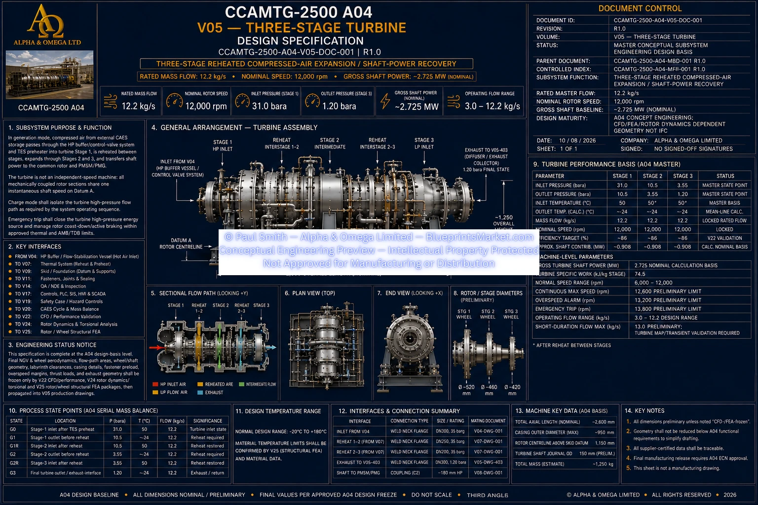
CCAMTG-2500 A04 — Three-Stage Reheated Turbine System
Volume 05 defines the CCAMTG-2500 A04 three-stage reheated compressed-air turbine subsystem, providing
staged expansion and shaft-power recovery during generation operation. Compressed air is supplied through
the high-pressure buffer and turbine admission architecture, thermally conditioned before the first turbine
stage, reheated between successive stages, and expanded through the complete three-stage turbine train.
Recovered mechanical power is transferred through the common rotor architecture to the integrated
PMSM/PMG system, with the turbine coordinated with magnetic bearings, touchdown bearings, thermal systems,
controls, protection, structural supports and exhaust-return interfaces.
Three-Stage Turbine System Overview
- Three-stage reheated compressed-air expansion architecture
- Progressive energy recovery across three turbine stages
- Integrated shaft-power recovery during generation operation
- Common rotor architecture shared with the mechanically coupled machine train
- High-pressure turbine admission through the buffer and control-valve system
- Thermal preheating before the first expansion stage
- Interstage reheating between successive turbine stages
- Integrated magnetic bearing and touchdown-bearing support
- Controlled exhaust and return-flow interface
- Integrated instrumentation, protection and operating controls
Turbine Assembly Components
- Stage 1 nozzle guide vane assembly
- Stage 1 turbine wheel assembly
- Stage 2 nozzle guide vane assembly
- Stage 2 turbine wheel assembly
- Stage 3 nozzle guide vane assembly
- Stage 3 turbine wheel assembly
- Common turbine rotor and shaft interfaces
- Split and sectioned turbine casing
- Labyrinth sealing assemblies
- Diffuser and exhaust collector
- Coupling interfaces
- Magnetic bearing and touchdown-bearing interfaces
Stage 1 Expansion System
- Receives thermally conditioned compressed air from the turbine preheater path
- Uses a dedicated nozzle guide vane assembly to condition and direct the incoming flow
- Transfers expansion energy through the first turbine wheel
- Provides the first stage of shaft-power recovery
- Discharges expanded air toward the first interstage reheating system
- Aerodynamic performance is coordinated with the overall three-stage turbine architecture
Stage 2 Expansion System
- Receives compressed air following first-stage expansion and interstage reheating
- Uses a dedicated second-stage nozzle guide vane assembly
- Transfers additional expansion energy through the second turbine wheel
- Provides the intermediate stage of shaft-power recovery
- Discharges expanded air toward the second interstage reheating system
- Operates as an integrated part of the common serial-flow turbine train
Stage 3 Expansion System
- Receives reheated compressed air following the second expansion stage
- Uses a dedicated third-stage nozzle guide vane assembly
- Transfers the final planned stage of expansion energy through the third turbine wheel
- Completes the three-stage shaft-power recovery process
- Discharges into the turbine diffuser and exhaust collector system
- Interfaces with the downstream exhaust and return-flow architecture
Preheat & Interstage Reheat System
- Thermally conditions compressed air before turbine Stage 1
- Reheats expanded air between Stage 1 and Stage 2
- Reheats expanded air between Stage 2 and Stage 3
- Supports controlled thermal conditions at each turbine-stage inlet
- Coordinates turbine operation with the CCAMTG-2500 A04 thermal subsystem
- Integrates reheater isolation with the wider operating and hazard-control architecture
- Supports pressure-loss and thermal-performance coordination across the turbine train
Turbine Rotor & Common Shaft Integration
- All mechanically coupled turbine sections operate as part of the common rotor train
- Turbine shaft power is transferred through the integrated rotor architecture
- Rotor interfaces coordinate turbine operation with the PMSM/PMG system
- Coupling interfaces provide controlled mechanical power transfer between machine modules
- Rotor alignment is maintained around the common machine centreline
- Rotor integrity is coordinated with structural, fatigue and rotordynamic engineering
- Dynamic behaviour is evaluated across normal, transient and fault operating conditions
Nozzle Guide Vanes & Turbine Wheels
- Dedicated nozzle guide vane architecture for each turbine stage
- Dedicated turbine wheel architecture for each expansion stage
- Stage-specific aerodynamic flow conditioning
- Progressive energy extraction across the three-stage turbine train
- Aerodynamic profiles coordinated with turbine performance analysis
- Rotating components coordinated with structural and fatigue analysis
- Wheel, blade and vane designs integrated with the overall common-rotor architecture
Turbine Casing & Pressure Architecture
- Sectioned turbine casing enclosing the staged expansion system
- Pressure-boundary architecture coordinated with turbine operating conditions
- Casing design accommodates thermal gradients and operating transitions
- Structural interfaces accommodate connected piping and reheater loads
- Casing interfaces coordinate with rotor clearances and support reactions
- Split-line joints use engineered fastening and sealing arrangements
- Cold-end operation is considered within casing, sealing and material engineering
Labyrinth Seal System
- Multiple labyrinth sealing assemblies throughout the turbine architecture
- Controls internal leakage between turbine regions
- Designed around rotor motion and thermal-growth requirements
- Coordinates with turbine aerodynamic performance requirements
- Accounts for cold-end operating conditions
- Designed to avoid oil contact within the turbine flow path
- Supports stable rotor operation during approved operating transitions
Diffuser & Exhaust Collector
- Receives the final expanded airflow from turbine Stage 3
- Provides controlled diffusion of the turbine exhaust flow
- Collects and directs the turbine discharge toward the downstream system interface
- Designed to minimize unnecessary exhaust pressure losses
- Coordinates with the overall compressed-air return architecture
- Integrated with turbine casing, thermal and service-envelope requirements
Turbine Admission & Control System
- Controlled high-pressure turbine inlet admission
- Fail-safe turbine inlet control architecture
- Independent upstream high-pressure isolation
- Controlled reheater isolation
- Stage inlet and outlet temperature monitoring
- Redundant main compressed-air flow monitoring
- Redundant rotor-speed sensing
- Integrated rotor vibration and position monitoring
- Integration with PLC, SIS and machine protection functions
Generation Operating Sequence
- Verifies compressed-air supply and thermal-system availability before turbine loading
- Establishes magnetic-bearing levitation and required machine support systems
- Coordinates rotor preparation before high-pressure turbine admission
- Isolates conflicting high-pressure flow paths as required by the operating mode
- Introduces turbine inlet flow under controlled ramp conditions
- Enables turbine preheating and interstage reheating
- Transitions the integrated electrical machine from motoring support to generation
- Regulates turbine operation through the coordinated machine control architecture
Magnetic Bearing & Touchdown Bearing Integration
- Turbine rotor operates within the common active magnetic bearing architecture
- Radial magnetic bearing support is integrated with turbine rotor operation
- Axial magnetic bearing control manages turbine rotor thrust requirements
- Rotor-position monitoring supports active magnetic bearing control
- Touchdown bearings provide defined backup support for applicable fault conditions
- Bearing behaviour is coordinated with complete-machine rotordynamic analysis
- Fault coast-down behaviour is integrated with turbine protection logic
Safety & Protection System
- Fail-safe high-pressure isolation at the turbine energy-source interfaces
- Redundant rotor-speed sensing for overspeed protection
- Rotor vibration and position protection functions
- Magnetic-bearing fault management
- Touchdown-bearing protection during defined fault conditions
- Controlled shutdown following critical turbine or machine faults
- Guarding of high-energy rotating and pressure-containing components
- Controlled depressurization before maintenance access
- Independent overpressure protection for applicable blocked-in pressure volumes
- Emergency isolation integrated with the wider machine safety architecture
Trip & Controlled Shutdown Functions
- Overspeed protection initiates turbine energy isolation and controlled rotor response
- Magnetic-bearing instability initiates high-pressure energy isolation and approved coast-down strategy
- High vibration initiates controlled machine shutdown
- Cooling-system failure initiates unloading and controlled shutdown
- Emergency-stop and fire conditions initiate coordinated energy isolation
- High-pressure isolation and depressurization are coordinated with machine safety requirements
Manufacturing & Quality Engineering
- Controlled manufacturing documentation for turbine components and assemblies
- Precision machining of aerodynamic turbine components
- Controlled manufacture of rotating turbine components
- Defined rotor and coupling alignment requirements
- Controlled casing manufacturing and assembly
- Engineered critical-joint fastening and preload requirements
- Material, machining and inspection traceability
- Controlled design-release process for analysis-dependent turbine geometry
Rotor Balance, Assembly & Alignment
- Rotor balancing coordinated with the approved high-speed rotor study
- Modular rotor sections support independent balance and service operations
- Final turbine assembly preserves the common rotor datum
- Coupling and journal alignment verified during assembly
- Thermal operating effects incorporated into final alignment engineering
- Rotor assembly records maintain machining, material, balance and inspection traceability
Inspection, NDE & Traceability
- Material certification for critical turbine components
- Traceability of rotating components to their controlling engineering documentation
- Inspection requirements coordinated with structural and rotordynamic engineering
- Quality-plan hold, witness and review points
- Non-destructive examination of critical wheel, shaft, casing, weld and joint features
- Material heat and lot traceability
- Pressure-boundary inspection and test documentation where applicable
- Balance and machining records retained for critical rotating assemblies
Verification & Performance Acceptance
- Rotor operating performance verification
- Compressed-air flow verification
- Turbine shaft-power performance verification
- Stage pressure and thermal-performance verification
- Magnetic-bearing vibration performance verification
- Overspeed-protection verification
- Operating-mode transition verification
- Valve fail-state and turbine shutdown verification
- Protection-system functional verification
- Factory and site acceptance evidence
Interface Summary
- Machine general arrangement and common rotor architecture
- HP buffer vessel and turbine admission system
- Active magnetic bearing and touchdown-bearing system
- Thermal preheat, interstage reheat and cooling systems
- Structural skid and turbine support system
- PMSM/PMG electrical power-generation system
- Fasteners, critical joints and sealing system
- System architecture and functional integration
- QA, inspection, NDE and traceability system
- Assembly, rotor alignment and installation engineering
- Maintenance, removal and overhaul system
- Controls, PLC, SIS and SCADA architecture
- Commissioning and performance acceptance
- Safety-case and hazard-control architecture
- Thermodynamic and generation energy-balance model
- Turbine aerodynamic and performance analysis
- Rotor dynamics and torsional analysis
- Rotor, shaft, wheel and blade structural analysis
- Reliability, service and spare-parts engineering
Subsystem Documentation
- Three-stage turbine design specification
- Complete turbine assembly documentation
- Exploded turbine assembly documentation
- Stage-specific nozzle guide vane documentation
- Stage-specific turbine wheel documentation
- Turbine casing documentation
- Labyrinth sealing-system documentation
- Diffuser and exhaust collector documentation
- Detailed turbine bill of materials
- Turbine mechanical-load engineering documentation