CCAMTG-2500 A04 — Thermal, Cooling & Airflow Systems
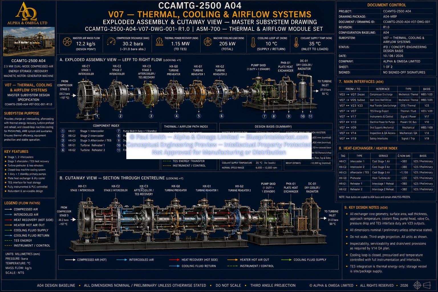
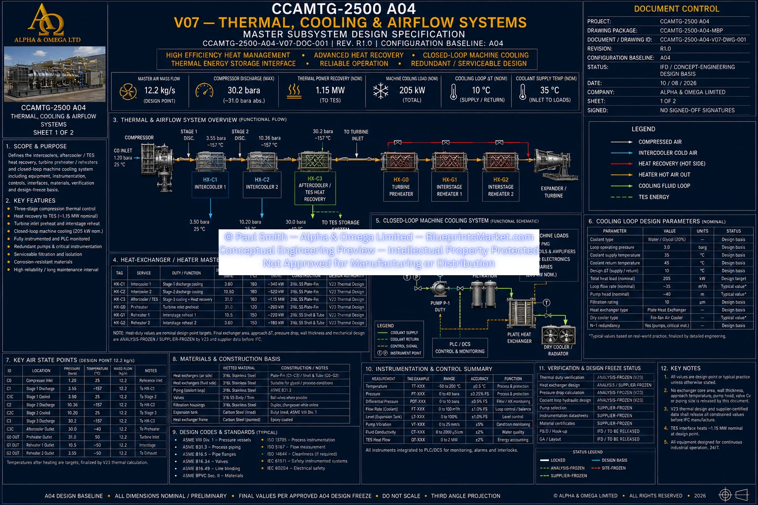
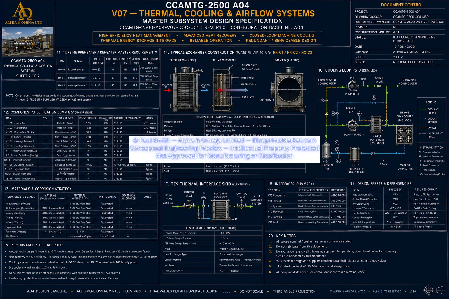
Volume 07 defines the CCAMTG-2500 A04 thermal, cooling and airflow subsystem, integrating compressor
intercooling, aftercooling and recoverable-heat transfer, turbine preheating and interstage reheating,
thermal-energy-storage interfaces, and the closed machine-cooling package. The subsystem supports thermal
stability across charge and generation operation while coordinating cooling, heat recovery, flow monitoring,
instrumentation, pressure and temperature control, component protection, and interface management throughout
the CCAMTG-2500 A04 architecture.
Thermal, Cooling & Airflow System Overview
- Multi-stage compressor intercooling
- Final compressor aftercooling and recoverable-heat capture
- Thermal-energy-storage interface
- Turbine high-pressure preheating
- Interstage turbine reheating
- Closed machine-cooling loop
- Redundant cooling-pump architecture
- Machine-loop heat rejection
- Cooling-system filtration and expansion management
- Flow, pressure, temperature and differential-pressure instrumentation
Compressor Intercooling System
- Dedicated intercooling following the first compressor stage
- Dedicated intercooling following the second compressor stage
- Removes compression heat before subsequent compression stages
- Supports stable inlet conditions for downstream compressor stages
- Transfers recoverable heat into the thermal-management architecture
- Includes inlet and outlet monitoring for pressure and temperature
- Includes isolation, drainage, venting and maintainability provisions
Aftercooling & Heat-Recovery System
- Final cooling following the last compressor stage
- Captures recoverable compression heat before the storage and buffer interface
- Transfers useful thermal energy to the TES-side thermal loop where practical
- Supports stable downstream compressed-air conditions
- Coordinates thermal duty with the storage and HP buffer architecture
- Includes pressure, temperature and differential-pressure monitoring
- Integrates isolation, drainage and maintenance functions
Thermal Energy Storage Interface
- Receives recoverable compression heat during charge operation
- Supplies thermal energy back to the turbine heating system during generation
- Interfaces with a closed thermal-fluid loop
- Supports bidirectional thermal-energy transfer
- Provides machine-side isolation for service and fault containment
- Includes expansion and overpressure-protection functions
- Includes temperature, pressure and flow instrumentation
- Integrates with PLC, SIS and HMI functions
Turbine Preheater System
- Thermally conditions compressed air before turbine Stage 1 admission
- Uses recovered or stored thermal energy where practical
- Supports stable turbine inlet thermal conditions
- Coordinates with turbine admission controls and permissives
- Integrates temperature, pressure and flow monitoring
- Prevents turbine admission when required thermal conditions are not satisfied
- Interfaces with the high-pressure buffer and turbine control architecture
Interstage Turbine Reheating
- Reheats expanded air between turbine Stage 1 and Stage 2
- Reheats expanded air between turbine Stage 2 and Stage 3
- Restores suitable thermal conditions before subsequent expansion stages
- Reduces unacceptable cold-end thermal exposure
- Coordinates reheater operation with the turbine map and thermal limits
- Uses monitored pressure and temperature conditions at each reheat interface
- Integrates reheater isolation with safety and control logic
Machine Cooling Package
- Closed and pressurized machine-cooling loop
- Redundant primary coolant pumping
- Machine-loop heat exchanger
- Ambient heat-rejection package
- Pressurized expansion and inventory management
- Serviceable filtration system
- Coolant supply and return manifolds
- Isolation, check, balancing, control and bypass valves
- Flow, pressure, temperature and differential-pressure monitoring
Machine Cooling Consumers
- PMSM/PMG thermal losses
- Active magnetic bearing coil and amplifier losses
- Power electronics where connected to the common cooling loop
- Compressor and turbine auxiliary heat loads
- Local machine jackets and cooling branches where required
- Consumer-specific cooling verified against actual equipment losses
- Battery thermal management remains outside the common V07 cooling loop
Cooling Pump Redundancy & Flow Management
- Duty and standby pump architecture
- Automatic standby-pump start following applicable duty-pump failure
- Cooling flow verified before machine startup
- Branch balancing maintains required cooling to each consumer
- High-point venting and deaeration provisions
- Low-point drain provisions
- Piping and manifolds arranged to avoid air locking
- Flow routing coordinated with mechanical loads and equipment interfaces
Filtration & Coolant Condition Management
- Serviceable duplex filtration architecture
- Differential-pressure monitoring across filters
- Filter changeover capability during service conditions
- Expansion-tank monitoring for loop integrity
- Coolant inventory and pressure management
- Closed-loop cleanliness maintained throughout operation and maintenance
Thermal Instrumentation
- Compressor intercooler inlet and outlet pressure monitoring
- Compressor intercooler inlet and outlet temperature monitoring
- Aftercooler and heat-recovery monitoring
- Turbine preheater inlet and outlet monitoring
- Interstage reheater inlet and outlet monitoring
- TES supply and return monitoring
- Machine coolant supply and return monitoring
- Pump status and suction/discharge monitoring
- Filter differential-pressure monitoring
- Cooling-branch proof-of-flow monitoring where required
Control, Permissive & Trip Functions
- Blocks high-speed operation if machine cooling is not established
- Initiates controlled unloading and shutdown following cooling failure
- Coordinates compressor response to abnormal intercooler outlet conditions
- Limits or blocks turbine admission when preheat conditions are outside the required operating band
- Limits generation when reheater conditions threaten turbine thermal limits
- Starts the standby cooling pump when machine coolant flow is inadequate
- Provides high-temperature and low-flow protection
- Provides filter condition alarms and service-changeover functions
- Coordinates safe response to loss of thermal-energy-storage availability
- Integrates thermal response with fire and emergency-stop logic
Materials & Compatibility Architecture
- Pressure- and corrosion-resistant process-air exchanger materials
- Materials suitable for cyclic thermal operation
- Thermal-loop piping compatible with the selected working fluid
- Pump wetted parts selected for thermal-fluid compatibility
- Gaskets and seals selected for pressure, temperature and chemical compatibility
- Critical fasteners controlled by joint-specific engineering
- Industrial thermal insulation for energy and personnel protection
- Structural supports coordinated with skid and thermal-expansion loads
Mechanical Integration & Serviceability
- Thermal equipment integrated with the machine skid architecture
- Heat-exchanger and cooling-package supports coordinated with structural analysis
- Nozzle and piping loads controlled at equipment interfaces
- Thermal expansion considered in support and piping arrangements
- Condensate and low-point drainage routed to controlled drain systems
- Insulation and guarding provide personnel protection
- Service removal and maintenance access considered in equipment layout
Manufacturing, QA & Inspection
- Traceable materials for pressure-containing thermal components
- Qualified fabrication and welding procedures
- Pressure-boundary inspection and non-destructive examination
- Controlled dimensional inspection
- Pressure and leak testing appropriate to component duty
- Clean and contamination-controlled process-air passages
- Certified supplier data for pumps, valves, filters and thermal equipment
- Removable insulation where required for inspection and service
Verification & Acceptance
- Pressure-boundary and leak testing
- Heat-exchanger thermal-performance verification
- Pressure-loss verification
- Cooling-pump duty verification
- Standby-pump changeover testing
- Cooling-loop flow verification
- Filter condition and changeover testing
- Temperature-control verification
- Instrumentation calibration and I/O verification
- Cooling-trip and permissive testing
- Integrated factory and site acceptance verification
Safety & Thermal Protection
- Overpressure protection for applicable thermal and blocked-in sections
- Controlled isolation for service and fault containment
- Protection against loss of cooling
- Protection against excessive component temperature
- Management of cold-end thermal conditions
- Hot-surface and personnel protection
- Controlled drainage and leak management
- Safe thermal response integrated with the wider machine safety architecture
Interface Summary
- Air-intake and conditioned compressor inlet system
- Three-stage compressor subsystem
- HP buffer vessel and storage interface
- Three-stage turbine subsystem
- Active magnetic bearing system
- Structural skid and equipment supports
- Electrical auxiliaries and power electronics
- Fasteners, joints, gaskets and sealing system
- Manufacturing and fabrication engineering
- System architecture and interface control
- QA, inspection and NDE system
- Assembly, filling, flushing and installation
- Maintenance and service engineering
- Controls, PLC, SIS and alarm architecture
- Commissioning and performance acceptance
- Safety-case and hazard-control architecture
- Thermodynamic cycle model
- Compressor and turbine performance models
- Heat-exchanger and TES design system
- Factory and site acceptance testing
Subsystem Documentation
- Thermal and cooling design specification
- Thermal-system functional schematic
- Cooling-package general arrangement documentation
- Compressor intercooler arrangement documentation
- Aftercooler and TES heat-recovery documentation
- Turbine preheater documentation
- Interstage reheater documentation
- Coolant distribution and instrumentation documentation
- Thermal equipment bill of materials
- Machine cooling heat-balance calculations