CCAMTG-2500 A04 — Controls, PLC, SIS, HMI & SCADA
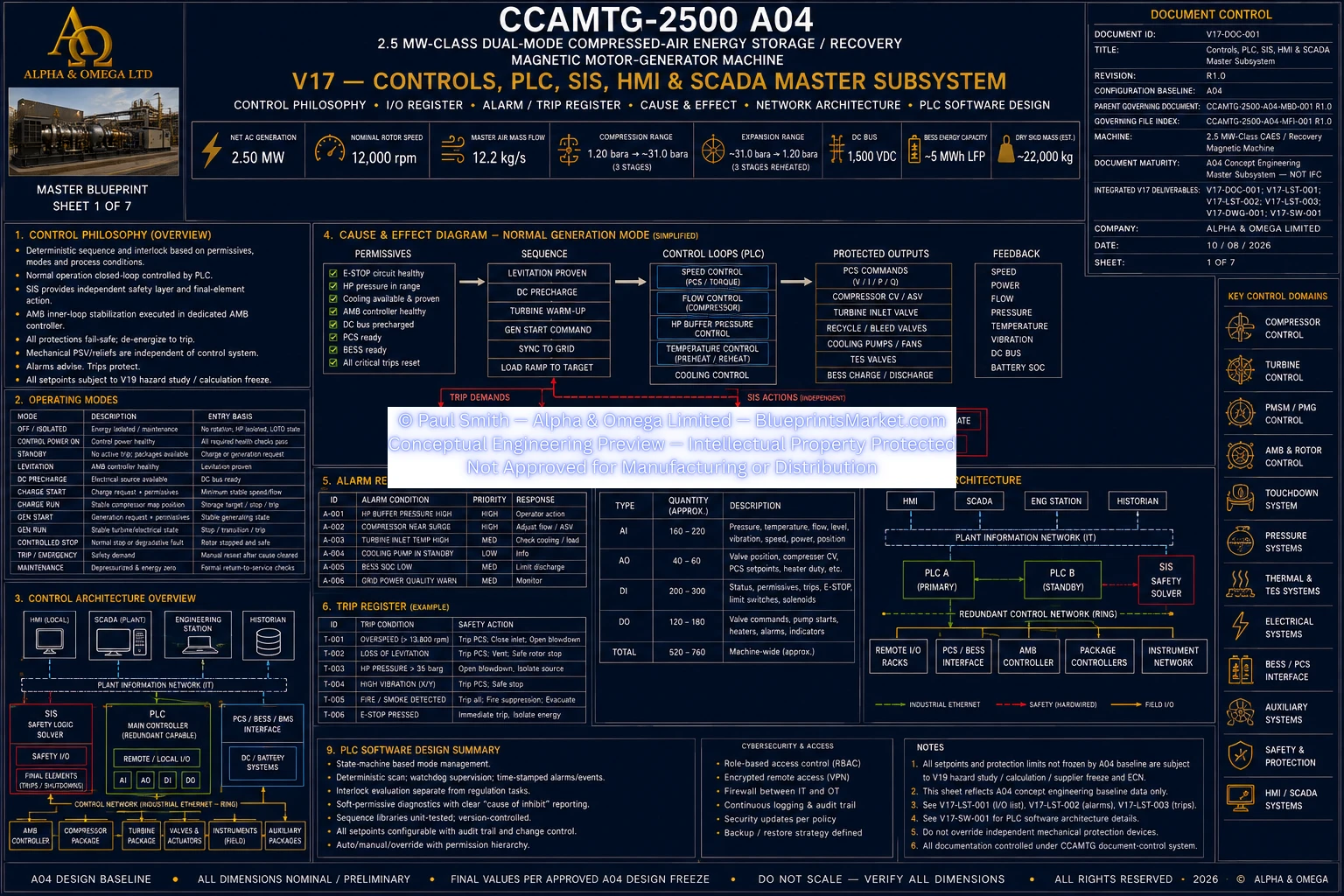
Volume 17 defines the complete machine-level controls and automation architecture for the CCAMTG-2500 A04,
integrating PLC sequencing, SIS protection, HMI and SCADA supervision, machine I/O, alarms, trips,
cause-and-effect logic, compressor anti-surge coordination, turbine control, rotor supervision,
magnetic-bearing interfaces, electrical conversion, BESS and PCS coordination, thermal controls,
industrial networking and controlled machine software.
Main Public Control Baseline
- Machine Class: 2.5 MW-Class Dual-Mode Compressed-Air Energy Storage / Recovery Magnetic Motor-Generator Machine
- Net AC Generation Target: 2.50 MW
- Nominal Rotor Speed: 12,000 rpm
- Master Air Mass Flow: 12.2 kg/s
- Compression Range: 1.20 bara → ~31 bara
- Expansion Range: ~31 bara → 1.20 bara
- DC Bus: 1,500 VDC
- BESS Energy Capacity: ~5 MWh LFP
A04 Controls Status:
Public values represent the current A04 control baseline. Final safety-trip settings, voting logic,
controller gains, network hardware, cybersecurity architecture, actuator response requirements and
supplier-specific limits remain controlled by the governing hazard, electrical, rotordynamic,
compressor, turbine and supplier design releases.
Controls Architecture Overview
- Main machine PLC
- Independent SIS / safety logic layer
- Local operator HMI
- Plant and site SCADA interface
- Remote and local I/O assemblies
- Industrial machine-control network
- Dedicated active magnetic bearing controller
- PCS and power-conversion controls
- BESS management system interface
- Compressor anti-surge controller
- Cooling-package control
- TES and thermal-control interface
Main PLC Responsibilities
- Deterministic machine sequencing
- Operating-mode state management
- Start and run permissive evaluation
- Machine interlock evaluation
- Non-safety closed-loop coordination
- Package-controller coordination
- Valve and auxiliary command coordination
- Machine status and operating-data publication
SIS & Independent Safety Layer
- Independent safety-trip functions where required by hazard allocation
- Safety final-element action
- Emergency shutdown coordination
- Hardwired or safety-rated emergency-stop integration
- Safety functions do not rely solely on the main PLC where independence is required
- Safety-trip settings remain governed by the approved hazard and protection studies
Active Magnetic Bearing Control Interface
- Dedicated AMB controller maintains rotor levitation and stability
- PLC exchanges enable, ready, levitated, centred, status and trip information
- Rotor-position and vibration data integrated into machine supervision
- Axial thrust-position monitoring integrated with machine status
- Touchdown-bearing health used as a machine permissive
- AMB inner-loop stabilization remains outside the PLC
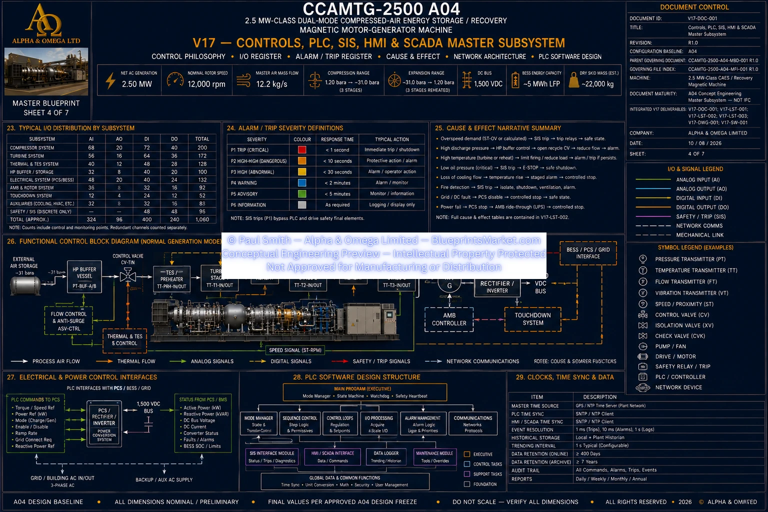
PCS & Motor-Generator Control Interface
- Motor torque coordination during charge operation
- Generator power coordination during recovery operation
- Speed and torque command exchange
- DC precharge status integration
- Converter ready and fault status
- Local current and electrical protection retained within the converter control system
BESS & BMS Control Interface
- Battery state-of-charge monitoring
- Battery availability monitoring
- Charge and discharge power-limit exchange
- Thermal and fire status monitoring
- BMS protection authority retained at battery level
- Machine energy-management logic respects BMS operating limits
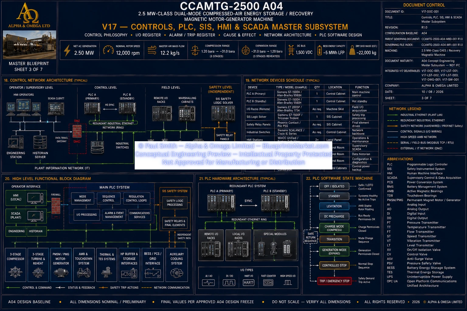
Operating State Machine
- Off / Isolated
- Control Power On
- Standby
- Levitation
- DC Precharge
- Charge Start
- Charge Run
- Generation Start
- Generation Run
- Controlled Stop
- Trip / Emergency
- Maintenance
Startup Permissives
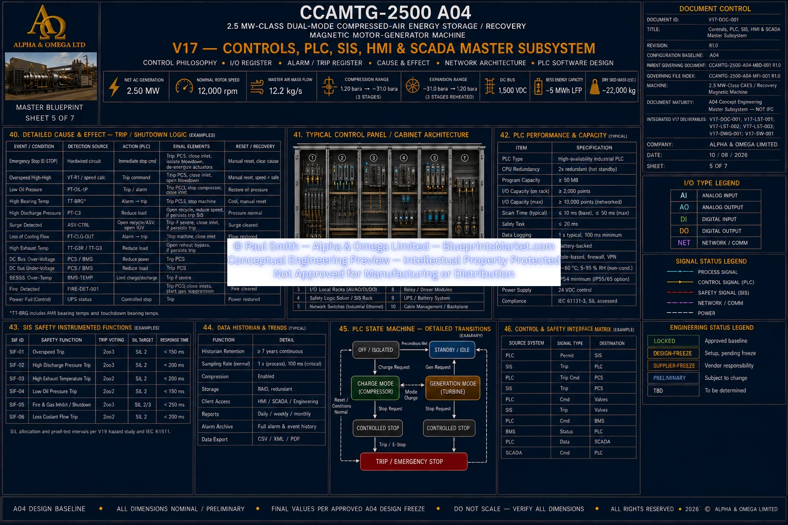
- Emergency-stop circuit healthy
- High-pressure system in an approved startup condition
- Cooling available and proven
- AMB controller healthy
- Rotor levitated and centred
- Touchdown-bearing monitoring healthy
- DC bus precharge complete
- Required grid, PCS and/or BESS source available
- Required isolation valves proven in commanded state
- No active critical machine-protection trip
Charge-Mode Control Sequence
- Establish AMB levitation
- Establish machine cooling
- Precharge the DC system
- Enable the inverter and PMSM motor function
- Accelerate the rotor to stable compressor operation
- Establish the compressor flow path
- Maintain protective anti-surge recycle during startup
- Progressively reduce recycle after stable flow develops
- Enable staged intercooling and thermal-energy capture
- Regulate compressor loading and storage pressure
- Unload and transition to standby or stop at the commanded storage condition
Generation-Mode Control Sequence
- Verify compressed-air storage availability
- Verify TES preheat and reheat availability
- Establish AMB levitation and machine cooling
- Establish the DC electrical system
- Isolate the compressor high-pressure path
- Establish the turbine flow path under controlled ramping
- Enable turbine preheat and interstage reheating
- Transition the PMSM/PMG toward generator operation
- Coordinate turbine input and generator torque
- Regulate shaft speed and commanded electrical export
Compressor Anti-Surge Control
- Uses compressor pressure measurements
- Uses corrected main airflow
- Uses shaft-speed information
- Uses compressor temperature inputs
- Protective recycle valve is configured toward a fail-open state
- Recycle remains open during initial compressor startup
- Recycle closes progressively after stable flow is established
- Protective demand returns recycle toward the safe protective state
- Final surge-margin and transient settings remain compressor-analysis controlled
Speed, Torque & Generation Control
- All mechanically coupled rotor modules share one instantaneous shaft speed
- PLC coordinates operating mode, speed and torque demands
- PCS maintains local converter current and torque loops
- Turbine admission and generator torque are coordinated during generation
- Rotor-speed regulation is maintained around the approved operating target
- Final control gains and ramp rates remain analysis and supplier controlled
Process Valve Control
- External compressed-air storage isolation
- Turbine inlet control
- Compressor discharge isolation
- Compressor anti-surge recycle control
- Reheater isolation
- Controlled buffer blowdown
- Reverse-flow prevention
- Valve-position proof integrated where required
Fail-Safe Final Element Philosophy
- External HP storage isolation moves toward a closed safe state
- Turbine inlet control moves toward a closed safe state
- Compressor discharge isolation moves toward a closed safe state
- Anti-surge recycle moves toward an open protective state
- Reheater safe states remain hazard-study controlled
- Independent mechanical pressure relief does not depend on PLC operation
- Blowdown safe-state philosophy remains safety-study controlled
Machine I/O Integration
- Compressor pressure signals
- Buffer-vessel pressure signals
- Redundant main airflow signals
- Compressor and turbine temperature signals
- Rotor position and vibration signals
- Redundant rotor-speed signals
- Filter differential-pressure monitoring
- Drain and condensate monitoring
- Emergency-stop health status
- AMB and touchdown-bearing status
- PCS, BMS and grid availability
- Cooling proof signals
- Valve commands and position feedback
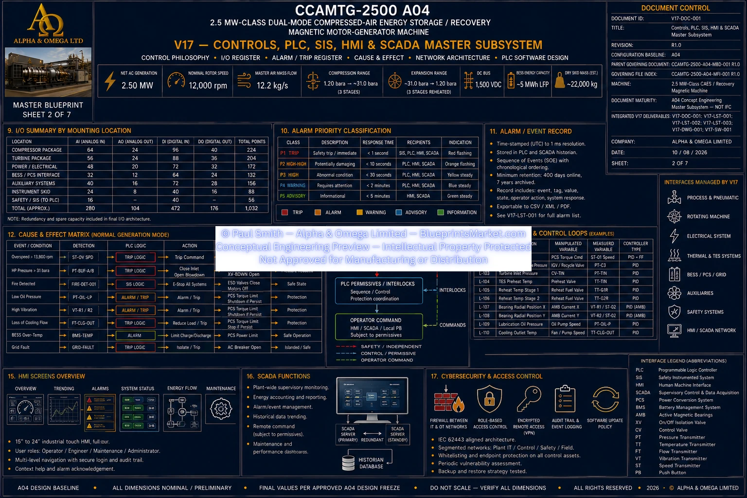
Alarm & Trip Architecture
- Rotor-speed alarms and protection
- Overspeed trip architecture
- High-flow supervision
- Buffer-pressure supervision
- High-vibration protection
- AMB instability protection
- Cooling-failure protection
- Electrical-fault protection
- Fire and emergency-stop protection
- Electrical insulation-fault protection
- BESS operating-state supervision
Cause & Effect Architecture
- Overspeed event response
- AMB instability response
- High-vibration response
- Buffer overpressure response
- Cooling-failure response
- Electrical-fault response
- Fire and emergency-stop response
- PLC-loss safe-state response
- HMI and SCADA loss response
- Final-element action coordinated with machine coast-down requirements
Loss of HMI or SCADA
- Local autonomous machine protection remains active
- Loss of supervisory displays does not defeat machine safety
- Final elements remain under local PLC, SIS or package authority
- Machine may continue locally or enter controlled stop according to operating policy
- Historian and supervisory data loss does not replace local protection
HMI Functional Pages
- Machine overview
- Charge and generation operating mode
- Rotor-speed and airflow overview
- Compressor process page
- Turbine and TES page
- AMB and rotor-condition page
- Electrical and DC-system page
- BESS status page
- Alarm and trip page
- Maintenance and diagnostics page
- Historical trends and event data
SCADA & Historian Functions
- Supervisory machine status
- Approved remote commands
- Operating-data historian
- Alarm and trip history
- Timestamped sequence-of-events records
- Electrical energy data
- Machine performance trends
- Maintenance and diagnostic data
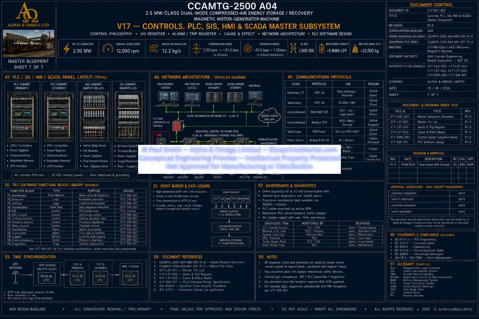
Control Network Architecture
- Safety network zone
- Machine-control network zone
- Rotordynamics and AMB control zone
- Power-conversion control zone
- Energy-storage and BMS zone
- Operator HMI zone
- SCADA and supervisory zone
- Auxiliary package-control zone
Safety Network Zone
- SIS logic solver
- Emergency-stop system
- Safety-rated I/O
- Allocated safety final elements
- Segregation maintained according to final safety architecture
Machine Control Network Zone
- Main PLC
- Remote I/O
- Package PLCs
- Sequence and interlock communications
- Deterministic industrial communications
- Redundancy applied where availability requires
Rotordynamics Control Zone
- AMB controller
- Rotor-position sensing
- Magnetic-bearing power amplifiers
- High-bandwidth real-time levitation control
- Supervisory communications to the machine PLC
Power Conversion Control Zone
- PCS
- Active rectifier
- Motor inverter
- Electrical meters
- Torque and power commands
- DC bus monitoring
- Local electrical protection
Energy Storage Control Zone
- BMS
- BESS
- Energy-management interface
- State-of-charge information
- Available power limits
- Battery thermal and safety alarms
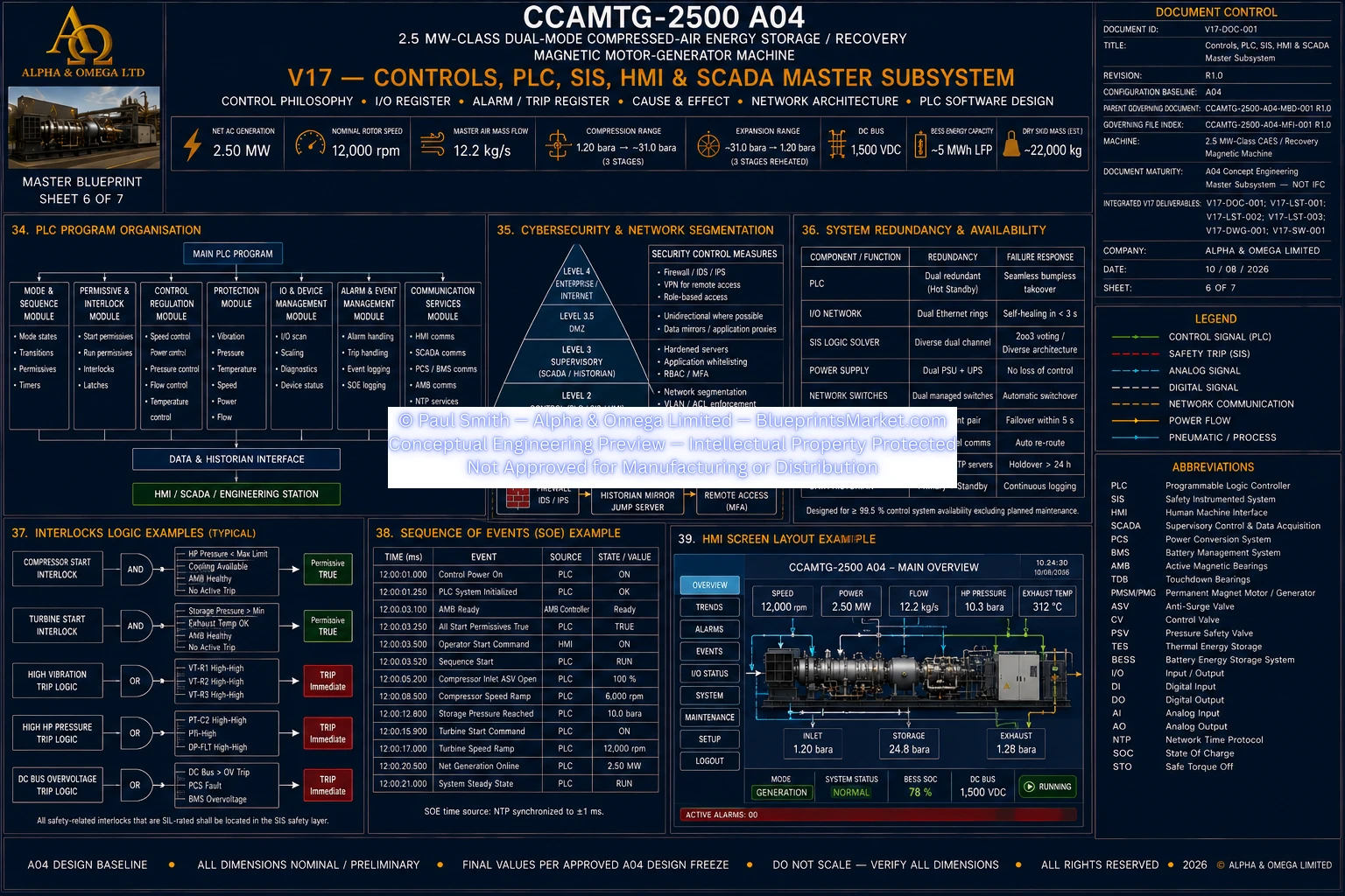
PLC Software Architecture
- Master state-machine module
- Permissive-management module
- Charge-sequence module
- Generation-sequence module
- Anti-surge supervision module
- Speed and torque coordination module
- Pressure-supervision module
- Thermal-control coordinator
- AMB interface module
- PCS interface module
- BMS interface module
- SIS interface module
- Alarm-management module
- I/O diagnostics
- HMI and SCADA data services
- Historian and event recorder
- Controlled maintenance-mode functions
Software Interlock Rules
- Trips latch where required by the approved safety analysis
- Trip reset requires the initiating cause to be cleared
- Safety interlocks cannot be bypassed by ordinary HMI commands
- Approved maintenance overrides require controlled authorization
- Maintenance overrides remain visibly indicated and event logged
- Failed start permissives return an explicit diagnostic reason
- Valve command and position feedback are compared where proof is available
- Redundant sensors are checked for disagreement
- Bad-quality network data is not silently treated as a healthy permissive
Alarm Management
- Alarm priority management
- Alarm latching where required
- Operator acknowledgement
- First-out trip indication
- Timestamped event sequence
- Alarm shelving only where permitted
- Alarm and trip history available to HMI and SCADA
Cooling & Thermal Control
- Duty and standby cooling-pump control
- Cooling flow and pressure proof
- Cooling temperature supervision
- Heat-exchanger and cooling-package status integration
- Charge-mode thermal-energy capture coordination
- Generation-mode preheat and reheat availability verification
- Cooling availability forms part of machine startup permissives
BESS Energy Management
- Normal battery dispatch
- Bulk charge management
- Automatic grid support when battery reserve declines
- Reserve-mode operation
- Controlled shutdown at the final BMS-defined critical minimum
- BMS remains authoritative for battery protection
Machine Protection Integration
- Independent mechanical overpressure protection
- Fail-safe high-pressure isolation
- Fail-open anti-surge protection
- Redundant rotor-speed sensing
- AMB fault management
- Touchdown-bearing coast-down support
- Fire-detection integration
- Electrical insulation monitoring
- Earthing and lockout provisions
- Controlled depressurization before maintenance
Control Panel & Hardware Philosophy
- Industrial control enclosures suited to the installation environment
- Safety, control and power functions segregated as required
- Remote I/O placed to reduce unnecessary field wiring
- Control power supports required safe coast-down functions
- Managed industrial network equipment
- Field wiring coordinated with EMC and cable-segregation requirements
- Instrument installation remains accessible and serviceable
- Safety final elements operate according to their approved fail-state philosophy
Verification & Functional Acceptance
- Rotor-speed regulation verification
- Main airflow verification
- Compressor pressure-performance verification
- Net electrical generation verification
- AMB vibration and stability verification
- Overspeed-trip verification
- Anti-surge transient verification
- Pressure-protection verification
- Operating-mode transition testing
- BESS control-interface testing
- Complete I/O point-to-point verification
- Complete released cause-and-effect functional testing
- Network-failure response testing
- Power-failure and restart-permissive testing
Configuration & Software Change Control
- PLC software version control
- SIS software and configuration control
- HMI and SCADA revision control
- Controlled release notes
- Checksum or equivalent software-integrity records
- Approved configuration backups
- Controlled rollback procedures
- I/O list revision control
- Alarm and trip register revision control
- Cause-and-effect revision control
- Software and controls configuration locked together for FAT and SAT
Control System Traceability
- Every safety trip traces to its originating hazard
- Every trip traces to its sensing element
- Every trip traces through logic and final-element action
- Every safety function traces to its verification procedure
- Every instrument is reconciled across process, I/O, alarm and commissioning documentation
- Every software change follows controlled engineering change management
V17 Controls Package
- Control Philosophy
- Master I/O List
- Alarm & Trip Setpoint Register
- Cause & Effect Matrix
- Control Network Architecture
- PLC Software Design Specification
- Operating-state architecture
- Permissive and interlock architecture
- HMI and SCADA functional requirements
- Configuration and software change-control requirements
Controls Release Philosophy
- Machine safety is not dependent on supervisory HMI or SCADA availability
- Independent mechanical pressure protection is not replaced by software
- AMB inner-loop control remains within the dedicated AMB controller
- BMS retains battery-level protection authority
- PCS retains local converter current and protection functions
- PLC coordinates the machine without overriding independent protection layers
- Unfrozen safety and control values remain controlled open items until their governing analyses are approved
- All final control logic, I/O, alarms, trips and software releases remain revision-controlled and traceable