CCAMTG-2500 A04 — Electrical Power Conversion & Energy Control
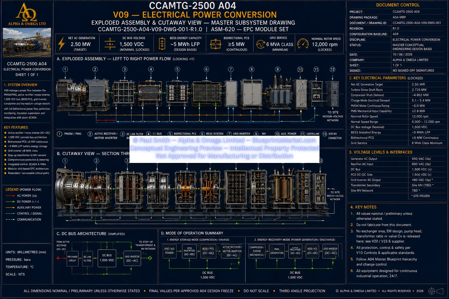
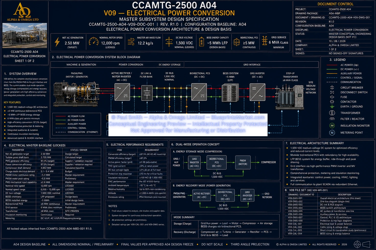
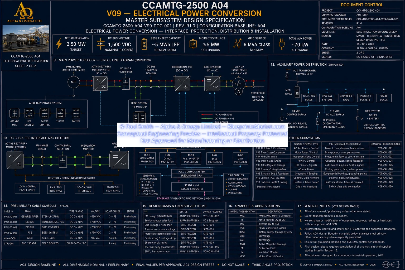
Volume 09 defines the CCAMTG-2500 A04 electrical power conversion subsystem, providing the bidirectional
electrical interface between the PMSM/PMG machine, common rotor, battery energy storage system, grid
connection and auxiliary control systems. The architecture supports motoring during charge operation,
electrical generation during turbine-driven operation, controlled transitions between operating modes,
DC power distribution, energy storage interfacing, grid conversion, protection, metering, auxiliary power,
earthing, bonding, cooling and coordinated machine-control functions.
Electrical Power Conversion System Overview
- Bidirectional PMSM/PMG power-conversion architecture
- Machine-side active rectifier and motor-inverter functions
- Common DC power-distribution system
- Battery energy storage and PCS interface
- Grid-side inverter interface
- Transformer and switchgear integration
- Auxiliary AC and DC control-power supplies
- Electrical metering and monitoring
- Protection, isolation and interlocking
- Earthing, bonding and cable-segregation architecture
Charge-Mode Electrical Operation
- Electrical energy supplied from the grid and/or approved energy-storage path
- Bidirectional power converter operates in motoring mode
- PMSM provides controlled torque to the common rotor and compressor system
- DC-bus regulation maintained throughout charge operation
- Current limiting protects the machine, converter and power-distribution system
- Precharge completed before main high-energy circuit closure
- Torque control coordinated with compressor and machine-control functions
Generation-Mode Electrical Operation
- Turbine-driven common rotor transfers mechanical power to the PMG
- Variable-frequency machine output converted through the active rectifier
- Generated electrical energy transferred into the common DC system
- Energy dispatched to the BESS and/or grid-conversion path
- Grid inverter manages export to the installation electrical system
- Power flow limited by machine, converter, storage and grid permissions
- Generation coordinated with turbine and rotor-speed control
Standby & Transition Modes
- Safety and control systems remain available during standby
- Main power paths isolated as required by operating state
- Auxiliary power maintained for PLC, SIS, AMB, cooling and instrumentation
- Controlled transfer between motoring and generating operation
- DC-bus stability maintained during operating transitions
- Reverse power and uncontrolled electrical transients prevented
- Rotor and magnetic-bearing stability preserved during mode changes
PMSM/PMG Electrical Interface
- High-speed permanent-magnet synchronous motor/generator architecture
- Variable-frequency three-phase machine interface
- Bidirectional operation for motoring and generation
- Industrial inverter-duty electrical insulation system
- Dedicated machine terminal assembly
- Cooling interface integrated with the machine thermal system
- Electrical-machine control coordinated with rotor-speed and torque commands
Machine-Side Converter
- Bidirectional active rectifier and motor-inverter operation
- Motoring control during compressor charge operation
- Active rectification during turbine-driven generation
- Closed-loop torque and current control
- DC-bus regulation
- Safe converter blocking during faults
- Controlled electrical braking where approved energy absorption is available
- Protection against overcurrent, thermal overload and abnormal bus conditions
DC Power Distribution
- Common DC bus connecting machine conversion, energy storage and grid conversion
- DC-link energy storage and filtering
- Main DC switching and isolation architecture
- Controlled precharge before full bus energization
- Stored-energy discharge provisions
- Lockable service isolation
- Continuous insulation monitoring
- DC voltage and current measurement
Precharge & Isolation System
- Precharge path limits electrical inrush before main closure
- Bus voltage rise monitored during energization
- Main isolation enabled only after acceptable precharge conditions are verified
- Precharge path removed or bypassed after verified main closure
- Faulted converters blocked before coordinated isolation
- Stored electrical energy discharged before maintenance release
- Lockout and verified isolation incorporated into service procedures
Battery Energy Storage Interface
- Bidirectional electrical interface to the battery energy storage system
- Battery-management permissive and trip integration
- State-of-charge and state-of-health monitoring
- Available charge and discharge power communicated to the energy-management system
- Battery voltage, current and thermal limits integrated with control logic
- Isolation and battery fault status monitored
- Fire, gas and thermal alarms integrated with emergency shutdown logic
- PCS active and reactive power commands coordinated with system operation
Grid Inverter & Utility Interface
- Bidirectional grid-conversion architecture
- Grid-code compliance coordinated with the installation jurisdiction
- Controlled electrical import during charging
- Controlled electrical export during generation
- Reactive-power and power-factor capability coordinated with site requirements
- Grid synchronization and anti-islanding functions
- Harmonic performance coordinated through grid and converter studies
- Utility and site protection requirements integrated with machine protection
Transformer & Switchgear
- Site-rated transformer interface
- Grid switchgear and isolation
- Protection ratings coordinated with the electrical fault study
- Interlocking between converter, transformer and switchgear systems
- Operational and revenue metering where required
- Site voltage and transformer ratio controlled by installation-specific engineering
- Switchgear fault duty and protection coordinated with the approved site study
Auxiliary Electrical Power
- Control power for PLC, SIS, HMI and SCADA
- Power supplies for active magnetic bearing controllers and amplifiers
- Cooling-pump and thermal-system auxiliary loads
- Converter cooling auxiliaries
- Valve actuator power
- Instrumentation and metering power
- UPS or ride-through support where required by the safety case
- Safe shutdown capability maintained independently of the main power path where required
Control-Power Philosophy
- Safety-critical controls do not rely solely on the main high-energy DC system
- Auxiliary control power supports safe machine shutdown
- Loss of normal auxiliary power generates alarms and controlled unloading actions
- Magnetic-bearing and cooling capability protected during power disturbances
- Emergency-stop functions use fail-safe or safety-rated architecture where required
- Control power integrated with wider machine hazard and safety functions
Electrical Metering & Monitoring
- DC bus voltage measurement
- DC current and power-flow measurement
- AC voltage and current measurement
- Active and reactive power monitoring
- Power-factor monitoring
- Frequency and energy measurement
- Converter temperature monitoring
- Cooling flow and temperature monitoring
- Rotor speed and phase-reference monitoring
- Breaker, contactor and disconnect status monitoring
Electrical Protection System
- Converter overcurrent and short-circuit protection
- DC overvoltage protection
- DC undervoltage protection
- Continuous insulation-fault monitoring
- Machine and converter thermal protection
- Grid fault and loss-of-grid response
- BESS fault isolation
- Overspeed coordination with machine torque removal
- AMB instability coordination with high-energy drive removal
- High-vibration shutdown coordination
- Cooling-failure derating and shutdown
- Fire and emergency-stop electrical isolation
Trip & Interlock Coordination
- Motoring torque removed during critical machine faults
- Generation blocked or limited during unsafe operating conditions
- Faulted electrical paths isolated in a coordinated sequence
- Rotor deceleration coordinated with available energy-absorption paths
- High-pressure process isolation coordinated with electrical trips
- Safe rotor coast-down preserved through active magnetic bearing support
- Reset permitted only after the initiating fault condition is cleared
Earthing & Bonding
- PMSM/PMG frame incorporated into the protective bonding network
- Machine skid and structural assemblies bonded
- Converter cabinets and switchgear bonded
- Transformer enclosure bonded
- Cable trays and guards bonded where required
- Dedicated low-impedance bonds used across removable interfaces where required
- Machine shaft-voltage and bearing-current mitigation coordinated with electromagnetic design
- Site earthing coordinated with installation-specific electrical engineering
EMC & Cable Segregation
- High-power DC routes segregated from low-level instrumentation
- Converter-to-machine power cabling controlled for high-frequency effects
- Grid and auxiliary AC cabling separated from sensitive control circuits
- Analog instrumentation uses shielded low-noise routing
- Safety I/O routing preserves independence where required
- Industrial network and fibre routes physically separated as required
- Cable shielding and screen termination coordinated with EMC requirements
- Redundant safety channels routed to reduce common-cause damage risk
Electrical Cooling Integration
- PMSM/PMG electrical losses incorporated into the machine cooling design
- Converter semiconductor losses transferred to the cooling system
- Converter cabinets include temperature monitoring
- Thermal derating and trip logic protects electrical equipment
- Cooling availability used as an electrical operating permissive
- Electrical thermal loads coordinated with the V07 thermal and cooling subsystem
- Battery thermal management remains a separate supplier package
Operating Control Exchanges
- Torque command and torque limit
- Motor and generator mode command
- Speed reference and actual rotor speed
- Converter ready, running and fault status
- DC bus ready, voltage, current and power status
- Precharge complete and main isolation status
- BESS state-of-charge, state-of-health and available power limits
- Grid availability and import/export limits
- Cooling permissive and thermal-derating status
- Emergency-stop and SIS trip signals
Electrical Load Management
- Main PMSM motoring load during charge operation
- PMG electrical generation during turbine operation
- Active magnetic bearing system loads
- Cooling-pump loads
- Converter cooling loads
- PLC, SIS, HMI and SCADA loads
- Valve actuator loads
- Instrumentation loads
- Battery thermal-system interfaces
- Essential and non-essential electrical loads identified through detailed design
Switchgear & Protection Engineering
- Unique identification for protective devices and circuits
- Protection functions coordinated with fault and selectivity studies
- Breaker and switchgear ratings verified against installation fault duty
- Protection interlocks coordinated across mechanical, electrical and software systems
- Arc-flash and fault-containment requirements addressed through detailed study
- Protection testing coordinated with factory and site acceptance procedures
Cable Engineering
- Unique cable identification
- Controlled source and destination references
- Power, control, instrumentation and network classifications
- Voltage and insulation requirements
- Shielding and armour where required
- Controlled routing through trays, conduits and penetrations
- Ampacity and voltage-drop verification
- Short-circuit withstand verification
- Termination and gland control
- Testing and continuity verification
Factory & Site Verification
- Electrical document consistency audit
- Insulation and continuity testing
- Precharge sequence verification
- DC-bus regulation verification
- Bidirectional converter functional testing
- Protection and interlock testing
- Electrical metering calibration
- PMG generation functional verification
- BESS energy-management interface testing
- Grid protection and synchronization verification
- Electrical thermal-performance verification
- Emergency-stop and safe-isolation verification
Safety & Electrical Isolation
- Lockable electrical service isolation
- Verified stored-energy discharge before maintenance
- Fail-safe response to critical electrical faults
- Independent protection where required by the safety architecture
- Electrical isolation coordinated with process high-pressure isolation
- Safe rotor coast-down preserved during machine trips
- Hazardous electrical conditions controlled through approved protection studies
- Maintenance release only after verified safe electrical state
Interface Summary
- General arrangement and equipment service envelopes
- Three-stage compressor torque and drive requirements
- Three-stage turbine generator and trip coordination
- Active magnetic bearing and touchdown-bearing power requirements
- Thermal and cooling subsystem
- Structural skid, equipment supports and cable routes
- Controls, PLC, SIS, HMI and SCADA architecture
- PMSM/PMG electromagnetic design
- Electrical protection, grid and earthing studies
- Battery energy storage and BMS architecture
- QA, inspection and commissioning systems
- Safety-case and hazard-control architecture
Subsystem Documentation
- Electrical Power Conversion master subsystem specification
- Electrical single-line diagram
- DC power-distribution documentation
- Active rectifier and motor-inverter schematic
- Grid inverter and transformer single-line documentation
- Earthing and bonding diagram
- Cable-routing and segregation documentation
- Electrical load list
- Cable schedule
- Switchgear and protection schedule
- Electrical current and thermal calculations
- Factory and site acceptance records