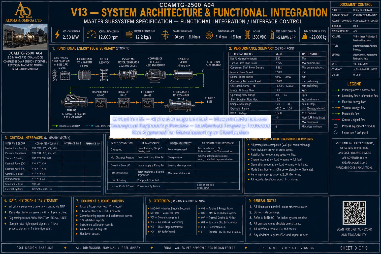
CCAMTG-2500 A04 — System Architecture & Functional Integration
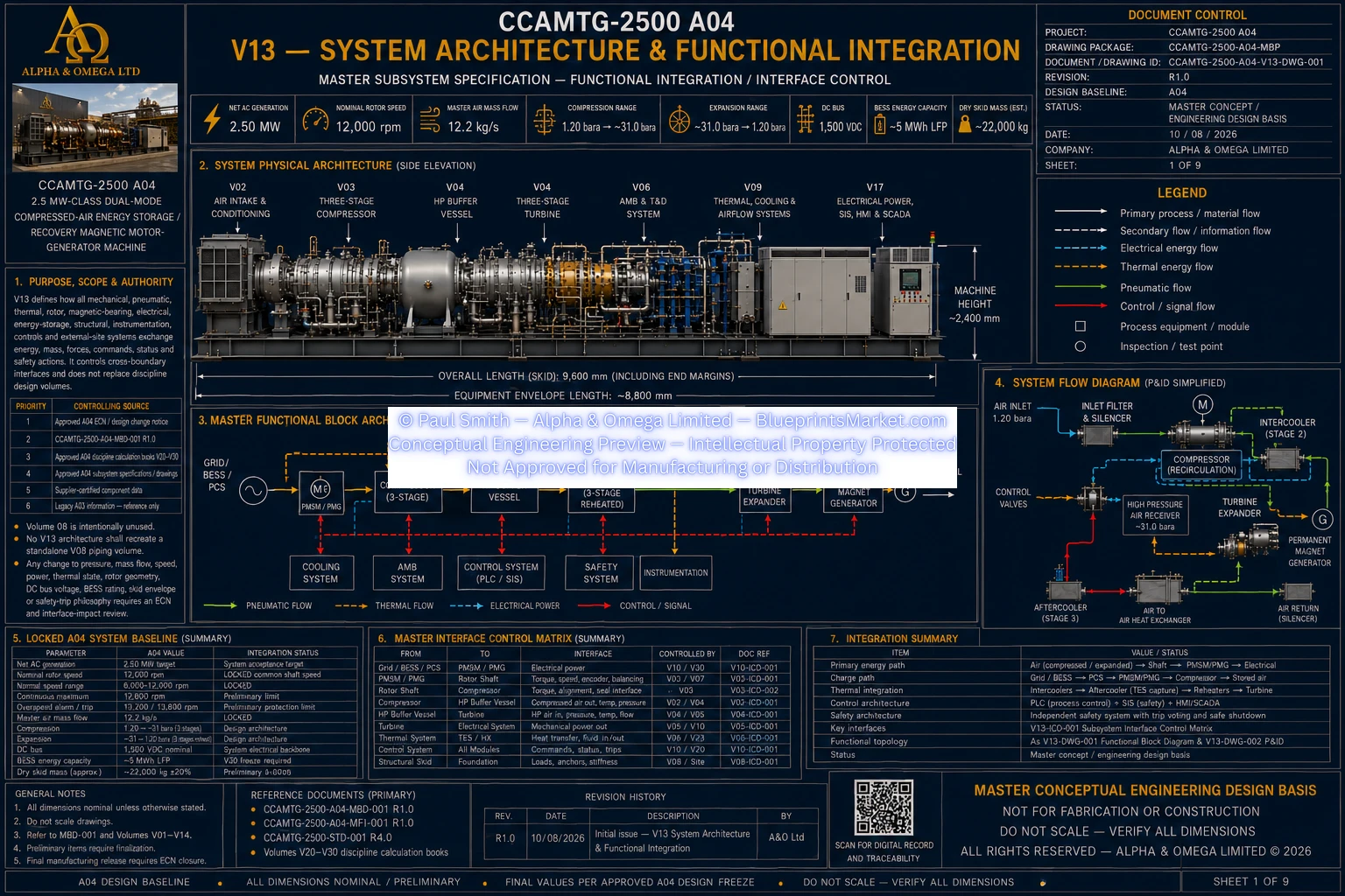
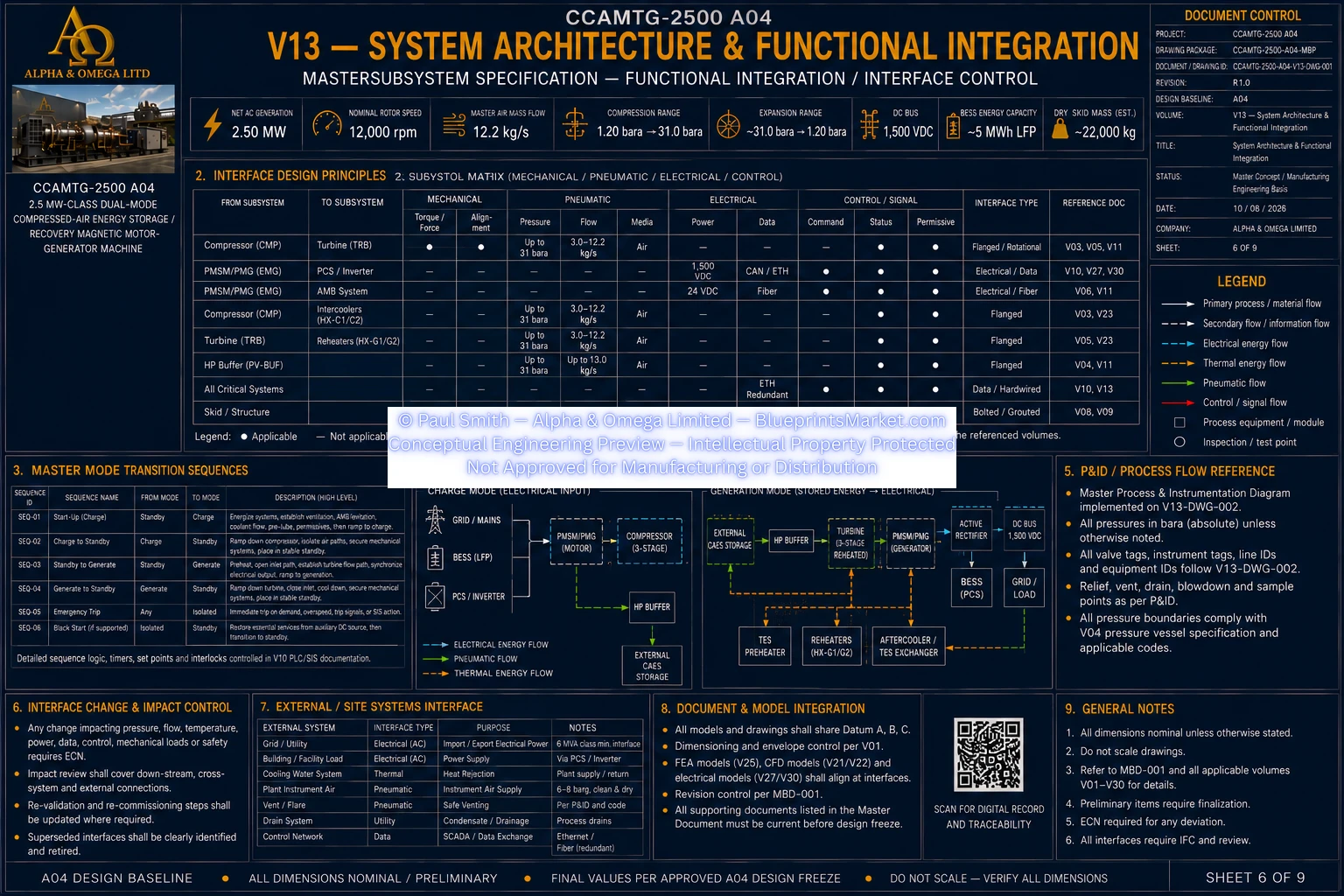
Volume 13 defines the system-level architecture and functional integration of the CCAMTG-2500 A04,
coordinating how the compressor, turbine, common rotor, PMSM/PMG, active magnetic bearings, touchdown
bearings, thermal-energy system, HP buffer vessel, external compressed-air storage, battery energy storage,
electrical conversion, structural skid, instrumentation, controls, protection and external site systems
operate as one integrated machine.
Main Public System Specifications
- Machine Class: 2.5 MW-Class Dual-Mode Compressed-Air Energy Storage / Recovery Magnetic Motor-Generator Machine
- Net AC Generation: 2.50 MW
- Nominal Rotor Speed: 12,000 rpm
- Master Air Mass Flow: 12.2 kg/s
- Compression Range: 1.20 bara → ~31 bara
- Expansion Range: ~31 bara → 1.20 bara
- DC Bus: 1,500 VDC
- BESS Energy Capacity: ~5 MWh LFP
- Dry Skid Mass (Estimated): ~22,000 kg
A04 Design Baseline:
Published specifications represent the current CCAMTG-2500 A04 design baseline. Final analysis-dependent,
supplier-dependent, code-dependent and site-dependent values remain controlled by the applicable approved
engineering calculations and drawings.
System Architecture Overview
- Mechanical system integration
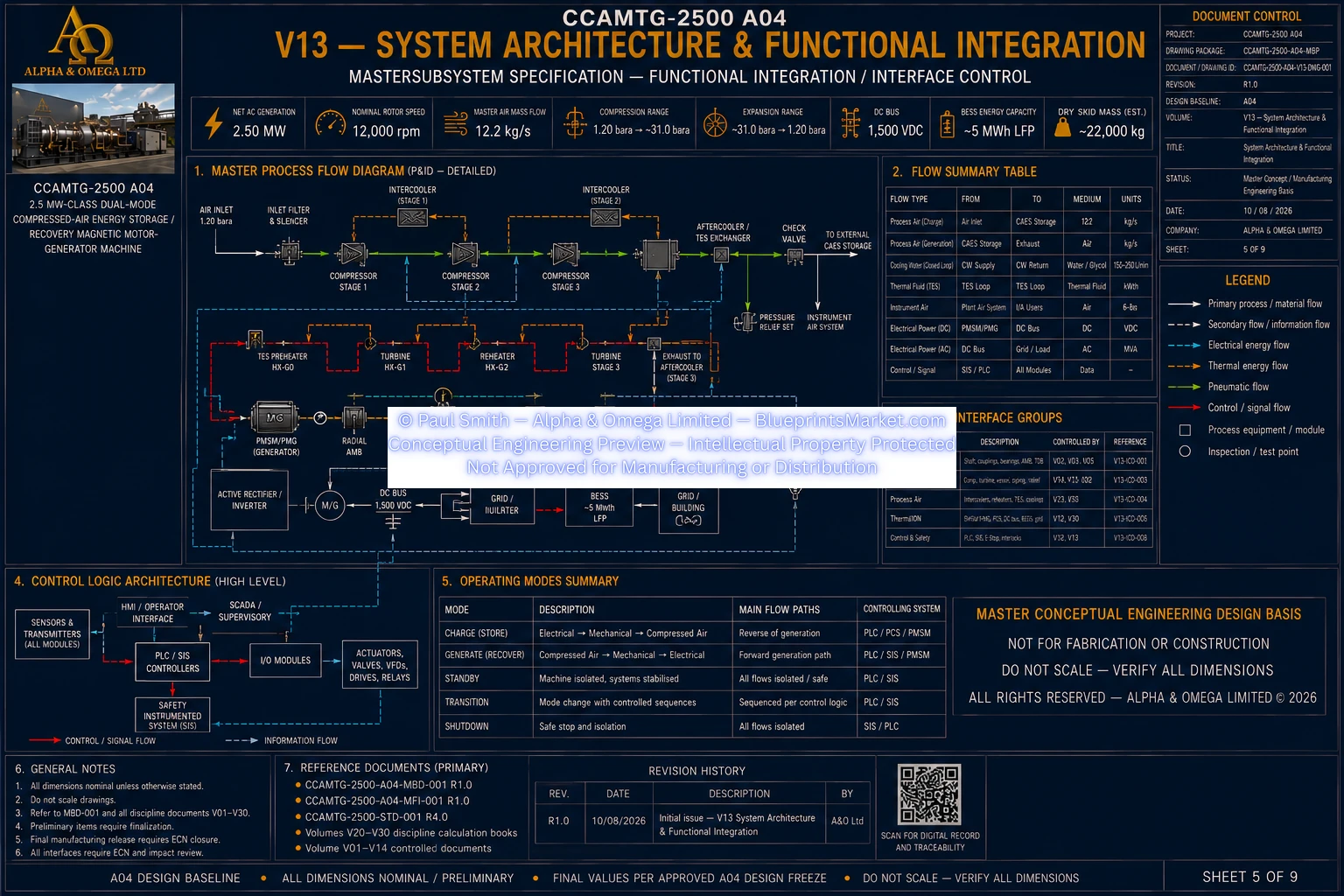
- Pneumatic process integration
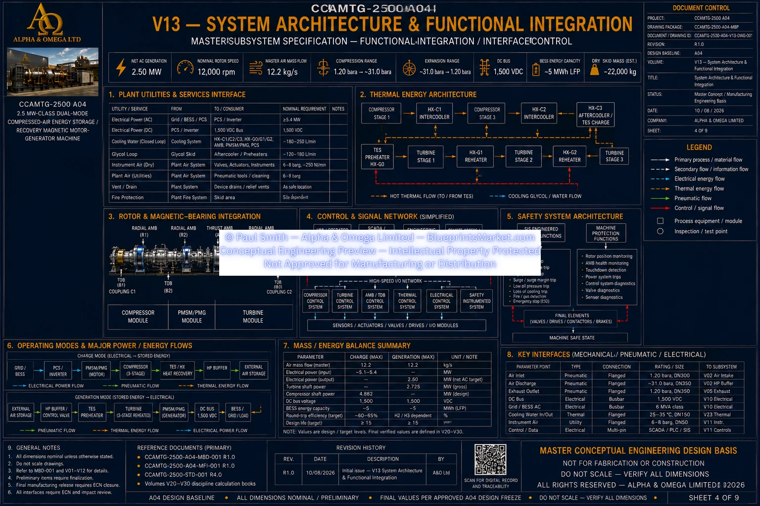
- Thermal-energy integration
- Common rotor integration
- Active magnetic bearing integration
- Electrical power-conversion integration
- Battery energy-storage integration
- Structural and foundation integration
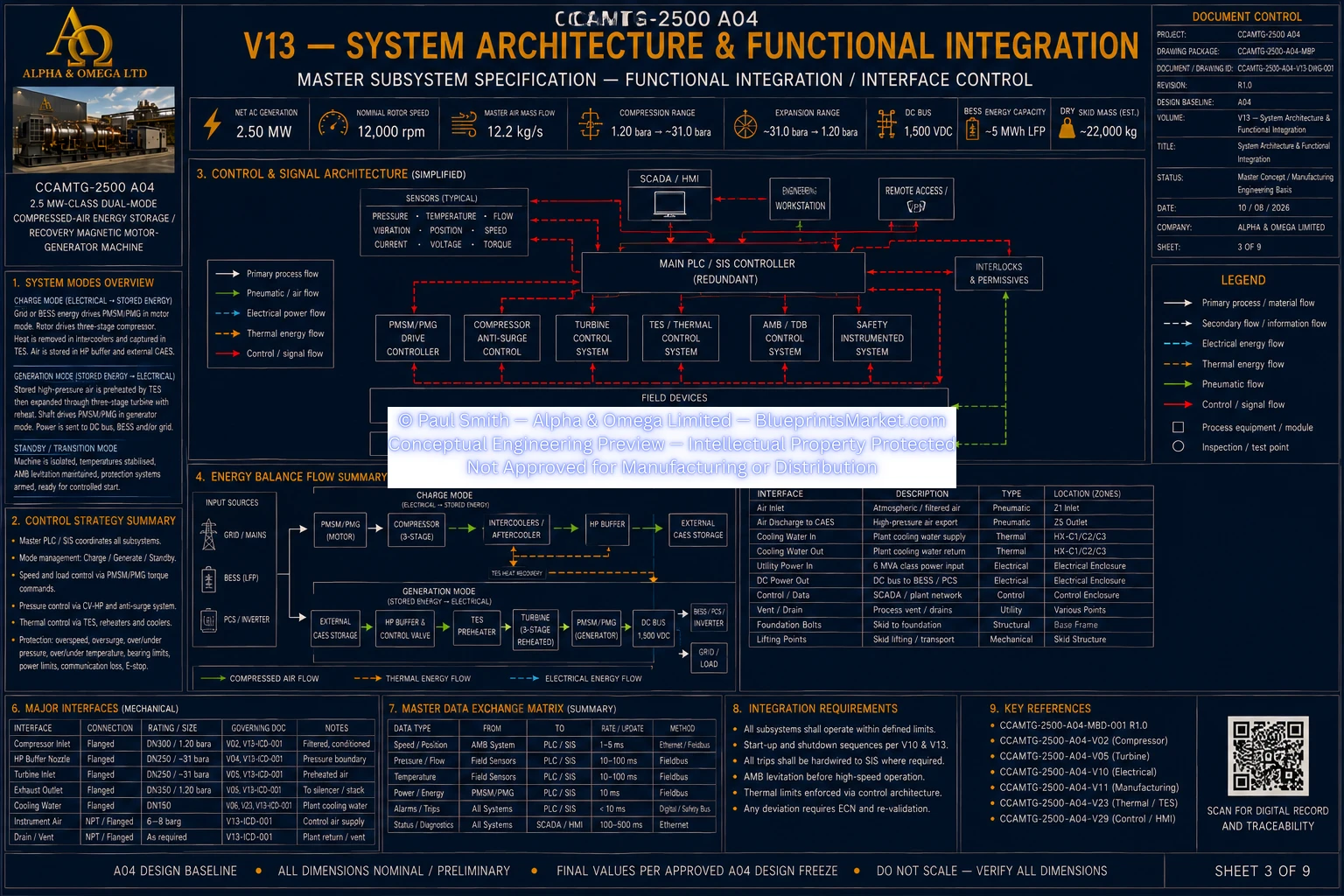
- Instrumentation and controls integration
- Safety and machine-protection integration
- External site-interface control
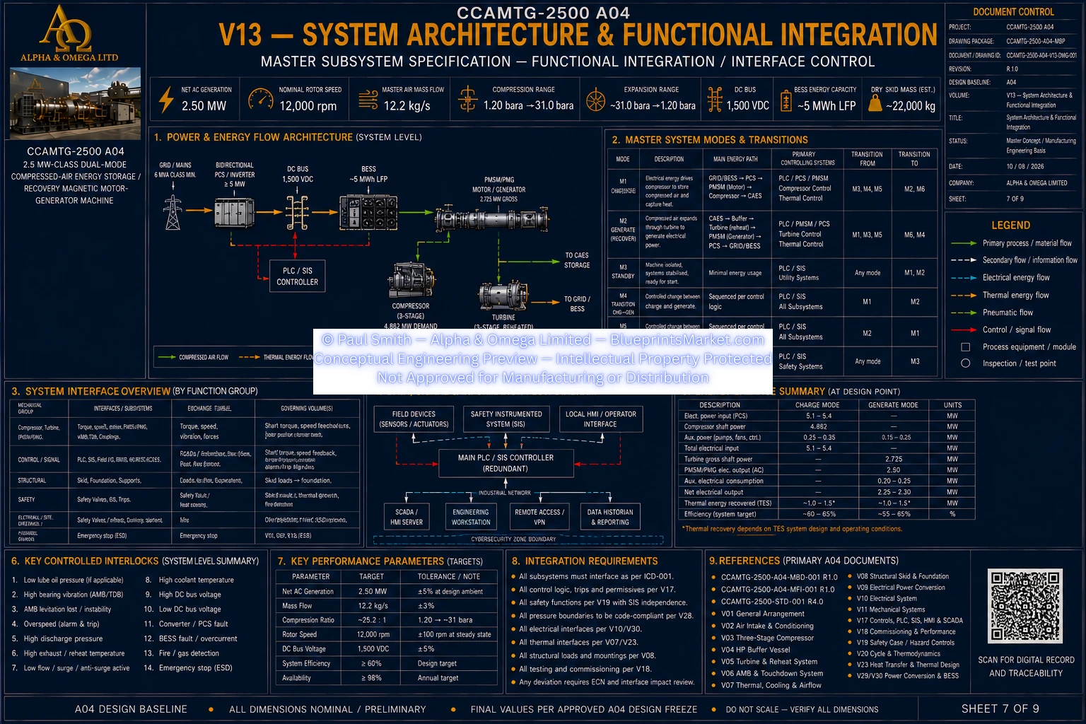
Charge Electrical Path
- Grid and/or BESS energy supplied through the electrical conversion architecture
- Electrical power routed through switchgear and power-conversion equipment
- Common DC system supplies the motor inverter
- PMSM/PMG operates in motor mode during charge operation
- Electrical control coordinated with rotor speed and compressor loading
Charge Mechanical Path
- PMSM/PMG develops shaft torque
- Torque transfers through the common rotor architecture
- Three-stage compressor receives the motoring power
- Coupling interfaces accommodate approved rotor and thermal behaviour
- Mechanical operation remains coordinated with magnetic-bearing support
Charge Pneumatic Path
- Ambient air enters through the intake and filtration system
- Conditioned air enters the three-stage compressor
- Compressed air passes through staged intercooling
- Final compressed air passes through aftercooling and heat recovery
- HP buffer vessel stabilizes the downstream compressed-air path
- Compressed air is transferred to the external CAES storage interface
Charge Thermal Path
- Compression heat is recovered from the intercooling and aftercooling systems
- Recovered heat transfers into the closed thermal-energy loop
- Thermal energy is directed to TES storage or approved heat rejection
- Thermal control coordinates with compressor operation and storage state
- Recovered thermal energy remains available for generation-mode reuse
Generation Pneumatic Path
- Stored compressed air returns from the external CAES system
- Fail-safe isolation controls the storage interface
- Compressed air passes through the HP buffer vessel
- Turbine admission control regulates the generation flow path
- Air is preheated before the first turbine stage
- Three-stage expansion includes interstage reheating
- Final turbine exhaust is routed to the defined discharge or return interface
Generation Mechanical Path
- Turbine expansion produces shaft torque
- Turbine wheels transfer mechanical energy into the common rotor
- High-speed couplings transfer torque between machine modules
- Common rotor drives the PMSM/PMG in generator operation
- Rotor support and thrust control remain coordinated with the AMB system
Generation Electrical Path
- PMSM/PMG operates in generator mode
- Generated variable-frequency electrical power passes through active rectification
- Electrical energy transfers into the common DC system
- Bidirectional PCS manages energy flow
- Generated power can be directed to the BESS and/or grid interface
- Electrical protection remains active throughout generation
Machine Cooling Integration
- Closed cooling package serves the PMSM/PMG
- Converter and PCS thermal loads integrated where applicable
- AMB amplifier thermal loads integrated with machine cooling
- Machine auxiliaries included within the cooling architecture
- Heat rejection coordinated with site ambient conditions
- Cooling availability forms part of operating permissives and trip logic
Common Rotor Integration
- Compressor, PMSM/PMG and turbine share one instantaneous shaft speed
- Rotor sections integrated through high-speed diaphragm couplings
- Common rotor centreline provides the principal rotating-machine datum
- Rotor architecture supports modular balancing and serviceability
- Rotor interfaces coordinated with rotordynamics, torsional and structural analysis
- Thermal growth accommodated within the approved coupling and support architecture
Compressor & Anti-Surge Integration
- Three-stage centrifugal compression architecture
- Staged pressure rise and staged cooling
- Compressor operating state coordinated with shaft speed
- Protective anti-surge recycle architecture
- Anti-surge logic uses pressure, corrected flow, speed and temperature information
- Recycle cooling limits excessive inlet-temperature escalation
- Protective recycle system designed to move toward a safe state during applicable faults
Turbine & Reheat Integration
- Three-stage reheated turbine expansion architecture
- Preheater conditions the Stage 1 inlet
- First interstage reheater restores thermal conditions before Stage 2
- Second interstage reheater restores thermal conditions before Stage 3
- Turbine admission control fails toward the defined safe state
- Turbine operation coordinated with TES availability and machine protection
- Aerodynamic geometry remains controlled by the turbine engineering package
HP Buffer & External CAES Integration
- HP buffer vessel provides local pressure and flow stabilization
- Buffer interfaces with compressor discharge and external CAES storage
- Buffer interfaces with the turbine admission path
- External storage isolation uses fail-safe architecture
- Passive reverse-flow protection incorporated where required
- Independent mechanical overpressure protection retained
- Controlled blowdown and depressurization integrated with the safety system
Thermal & TES Integration
- Compression heat recovered during charge mode
- TES interface stores recoverable thermal energy
- Stored thermal energy supports turbine preheating and reheating during generation
- Thermal interfaces coordinated with heat-exchanger performance
- Machine cooling remains distinct from the BESS supplier thermal system
- Thermal sizing and pressure-loss values remain controlled by the thermal engineering package
Active Magnetic Bearing Integration
- Multiple radial magnetic bearing stations support the rotor train
- Axial magnetic bearing provides thrust control
- Rotor-position sensing supports closed-loop bearing control
- Redundant rotor-speed and phase sensing supports control and protection
- AMB system status forms part of machine startup permissives
- Fault conditions coordinate pressure isolation and rotor coast-down
Touchdown Bearing Integration
- Independent touchdown support at the radial bearing stations
- Backup mechanical support during defined levitation-loss events
- Fault coast-down coordinated with rotor dynamics and AMB control
- Touchdown bearing health monitored before machine startup
- Touchdown system remains separate from normal non-contact running support
PMSM/PMG Integration
- High-speed permanent-magnet motor-generator architecture
- Motor operation during charge mode
- Generator operation during generation mode
- Bidirectional mechanical-electrical energy conversion
- Closed machine-cooling interface
- Rotor retention and electromagnetic design coordinated with the common rotor system
Electrical Energy Architecture
- Bidirectional motor-generator power conversion
- Common DC electrical backbone
- Main isolation and precharge functions
- Continuous insulation monitoring
- Bidirectional PCS interface
- BESS energy-buffer interface
- Grid transformer and switchgear interface
- Electrical metering and protection architecture
BESS & Energy Management Integration
- BESS provides electrical energy buffering and support
- State-of-charge information integrated with machine dispatch logic
- PCS manages bidirectional battery energy flow
- BMS safety information integrated with the control system
- Energy-management strategy coordinates charging, generation and reserve operation
- Final BESS safety and dispatch settings remain supplier and analysis controlled
Valve & Safe-State Architecture
- External storage isolation configured toward a closed safe state
- Turbine inlet control configured toward a closed safe state
- Compressor discharge isolation configured toward a closed safe state
- Compressor anti-surge recycle configured toward an open protective state
- Reheater isolation coordinated with the hazard study
- Independent buffer overpressure relief remains mechanically available
- Controlled blowdown integrated with machine depressurization strategy
- Passive non-return devices prevent reverse flow where required
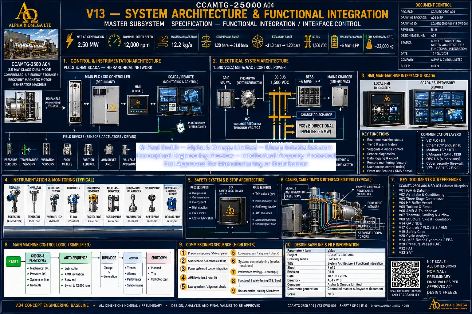
Instrumentation Integration
- Compressor pressure measurement
- Buffer-vessel redundant pressure monitoring
- Redundant main air-flow monitoring
- Compressor inlet and discharge temperature monitoring
- Turbine inlet and reheat temperature monitoring
- Turbine outlet temperature monitoring
- Rotor vibration and position monitoring
- Redundant rotor-speed measurement
- Filter-condition monitoring
- Condensate and drain monitoring where required
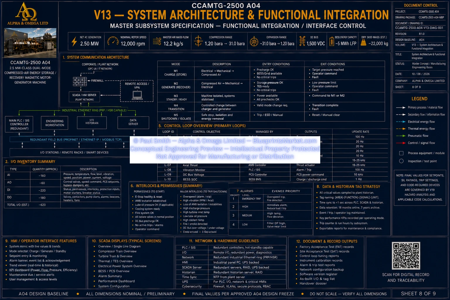
Operating State Machine
- Off / Isolated
- Standby
- Levitate / Prestart
- DC Precharge
- Charge Start
- Charge Run
- Generation Start
- Generation Run
- Controlled Stop
- Trip / Emergency
Startup Permissives
- Emergency-stop system healthy
- High-pressure system within approved startup state
- Cooling available and proven
- AMB controller healthy
- Rotor levitated and centred
- Touchdown-bearing monitoring healthy
- DC bus precharge complete
- Required electrical source available
- Isolation valves proven in commanded state
- No active critical protection trips
Charge-Mode Functional Sequence
- Establish magnetic-bearing levitation and machine cooling
- Precharge the electrical DC system
- Enable motor operation and accelerate the rotor
- Establish the compressor flow path
- Operate protective recycle during initial compressor loading
- Transition toward stable compressor flow
- Enable staged cooling and thermal-energy recovery
- Control storage pressure within the approved operating envelope
- Unload and transition to standby or stop at the commanded storage state
Generation-Mode Functional Sequence
- Verify external storage and thermal-energy availability
- Establish magnetic-bearing levitation and cooling
- Establish the electrical DC system
- Isolate the compressor high-pressure path
- Introduce turbine inlet flow under controlled ramping
- Enable turbine preheat and interstage reheating
- Transition the PMSM/PMG from motoring support to generation
- Regulate rotor speed and electrical export
- Maintain approved flow, thermal and pressure conditions
Trip & Safe-Shutdown Integration
- Overspeed initiates turbine energy isolation and torque removal
- AMB instability initiates high-pressure isolation and coast-down strategy
- High vibration initiates controlled machine shutdown
- High buffer pressure isolates compressor discharge while independent relief remains available
- Cooling failure initiates unloading and controlled shutdown
- Electrical faults isolate affected power-conversion paths
- Fire and emergency-stop conditions initiate coordinated energy isolation
Subsystem Interface Control
- General arrangement and datum interfaces
- Air-intake and compressor interfaces
- Compressor and thermal-system interfaces
- Buffer-vessel and turbine interfaces
- Rotor and magnetic-bearing interfaces
- Thermal and electrical interfaces
- Manufacturing and QA interfaces
- Assembly and installation interfaces
- Maintenance and lifecycle interfaces
- Controls and safety interfaces
- Analysis and design-freeze dependencies
External Site Interfaces
- External compressed-air energy storage
- Bidirectional electrical grid connection
- Site foundation and structural interface
- Ambient heat-rejection interface
- Thermal-energy storage interface
- Drain and blowdown disposal interface
- Site utilities and control communications
Functional Completeness Rules
- Every manufactured part has controlled identification and inspection requirements
- Every purchased item has a defined procurement and supplier-data interface
- Every process connection has a controlled service and interface definition
- Every instrument is reconciled across process, controls and commissioning documentation
- Every electrical load is reconciled with load, cable and protection documentation
- Every safety function traces to hazard analysis, sensors, logic and final elements
- Preliminary values are not silently promoted to fabrication-release status
- Interface changes require controlled impact assessment
Design-Freeze Integration
- System baseline definition
- Thermodynamic state-point and energy-path freeze
- Compressor, turbine and thermal performance freeze
- Rotor dynamics and structural rotor freeze
- Magnetic-bearing and PMSM/PMG freeze
- Pressure, electrical-protection and BESS freeze
- Physical production-drawing integration
- Manufacturing, safety, assembly and controls integration
- Factory functional integration acceptance
- Site integration acceptance
- Final installed architecture handover
Verification & Acceptance
- Rated airflow verification
- Rotor-speed regulation verification
- Compression performance verification
- Turbine performance verification
- Net electrical generation verification
- AMB stability and vibration verification
- Anti-surge functional testing
- Pressure-boundary verification
- Mode-transition testing
- Electrical architecture verification
- BESS control-interface testing
- Emergency isolation and depressurization testing
System Integration Documentation
- System Architecture & Functional Integration Master Subsystem Specification
- Master Functional Block Diagram
- Master Process Flow Diagram
- Subsystem Interface Control Matrix
- Charge and generation functional paths
- Cross-subsystem interface ownership
- Operating-state and safe-state architecture
- Design-freeze dependency register
- Verification and acceptance traceability