CCAMTG-2500 A04 — HP Buffer Vessel & Flow Stabilization System
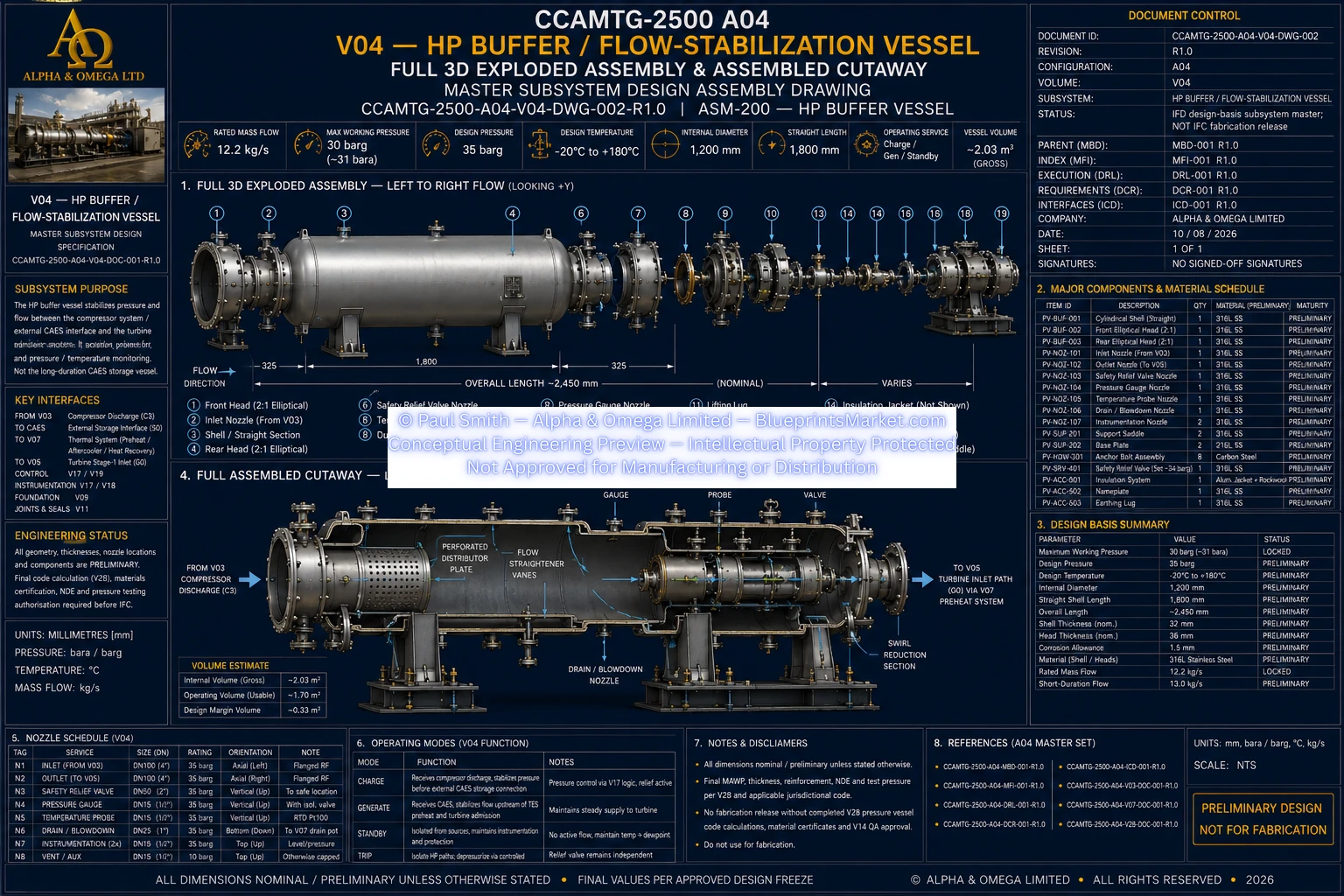
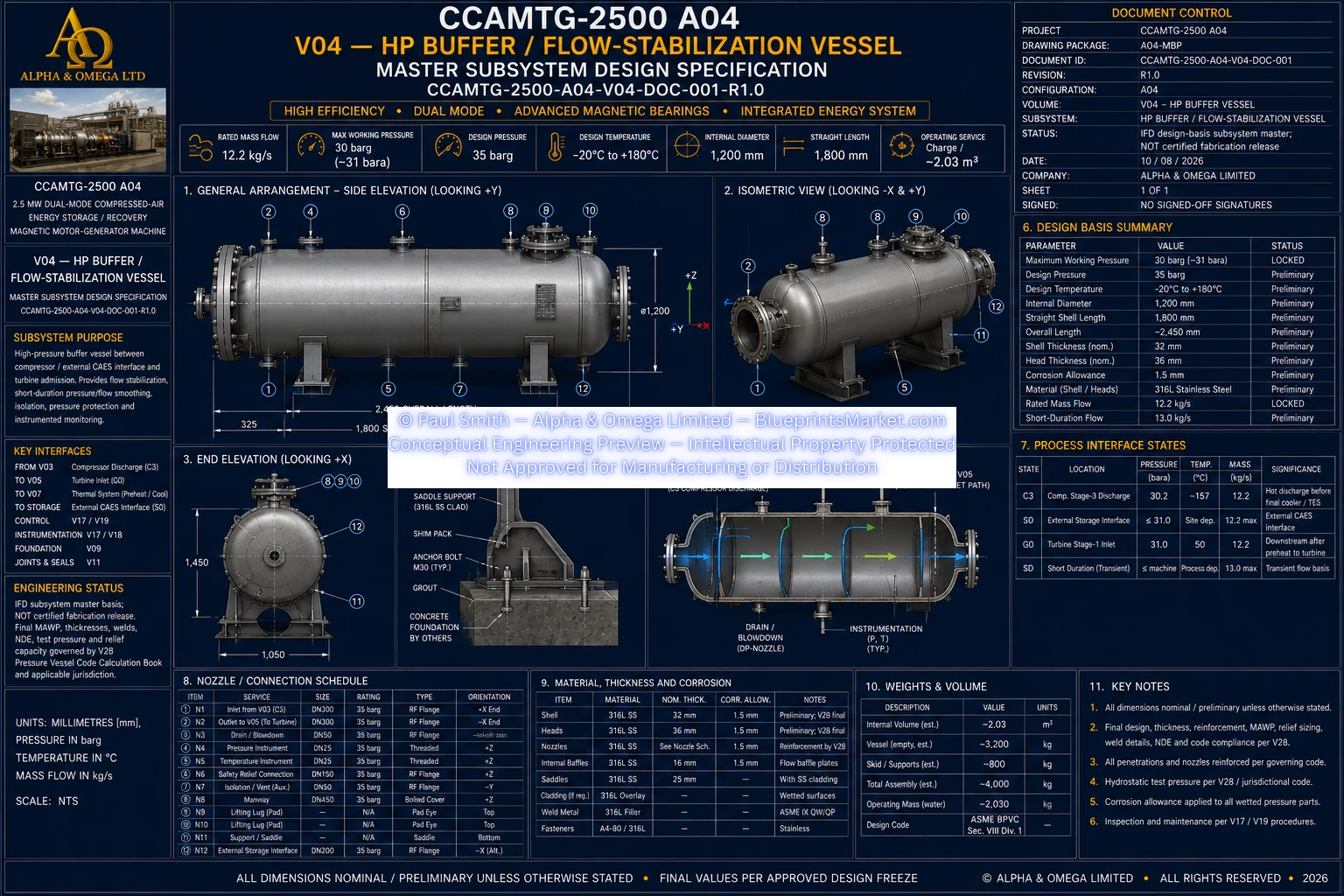
Volume 04 defines the CCAMTG-2500 A04 HP Buffer / Flow-Stabilization Vessel subsystem, providing the local
high-pressure compressed-air interface between the three-stage compressor, external CAES storage boundary,
thermal system and turbine admission path. The subsystem is designed to stabilize short-duration pressure
and flow disturbances, support controlled charge and generation transitions, provide isolation and independent
pressure protection, and deliver continuous pressure and temperature monitoring as part of the integrated
CCAMTG-2500 A04 architecture.
HP Buffer Vessel System Overview
- Local high-pressure compressed-air flow-stabilization subsystem
- Interfaces with the three-stage compressor discharge path
- Interfaces with external compressed-air energy storage (CAES)
- Supports the turbine admission and preheater supply path
- Stabilizes short-duration pressure and flow disturbances
- Supports controlled charge, generation, standby and trip transitions
- Provides instrumented pressure and temperature monitoring
- Provides isolation, overpressure protection and controlled depressurization functions
- Functions as a local buffer vessel rather than the long-duration CAES storage reservoir
Pressure-Boundary Assembly Components
- Horizontal pressure-vessel shell assembly
- Pressure-retaining vessel heads
- Qualified pressure-boundary weld system
- Main compressed-air inlet connection
- Main compressed-air outlet connection
- Independent pressure-relief connection
- Low-point condensate drain connection
- Controlled blowdown and depressurization connection
- Pressure instrumentation connections
- Temperature instrumentation connection
- Inspection and service access provision where required
- Structural vessel support and skid interfaces
Flow-Stabilization Functions
- Receives compressed air from the compressor and CAES charge path
- Provides a stabilized local high-pressure operating volume
- Supports controlled transition between charging and power-generation modes
- Supplies the downstream preheater and turbine admission path during generation
- Reduces short-duration pressure and flow disturbances between connected subsystems
- Supports low-pressure-loss integration with connected high-pressure piping
- Supports controlled system isolation during standby and trip conditions
Charge & Generation Operating Modes
- Charge Mode: compressor discharge and final cooling path feed the HP buffer vessel
- Charge Mode: the buffer supports the controlled interface to external CAES storage
- Generation Mode: external CAES supplies the controlled high-pressure buffer path
- Generation Mode: buffered compressed air feeds the thermal preheater and turbine admission system
- Standby Mode: high-pressure sources can be isolated while independent pressure protection remains available
- Trip Mode: the subsystem coordinates isolation and approved controlled depressurization functions
Valve & Pressure Protection System
- Fail-safe high-pressure isolation architecture
- Remote isolation capability for the external CAES interface
- Reverse-flow protection where required by the system architecture
- Redundant pressure-control functionality
- Independent high-pressure trip protection
- Independent mechanical overpressure relief
- Controlled blowdown and depressurization pathway
- Emergency trip coordination with connected compressor, turbine and control systems
Instrumentation & Monitoring
- Continuous buffer-vessel pressure measurement
- Independent high-high pressure protection sensing
- Continuous compressed-air temperature measurement
- Isolation-valve position and status monitoring where required
- Pressure-relief system status monitoring where required
- Drain-system status monitoring where safety-significant
- Local indication for commissioning, service and maintenance support
- Integration with the CCAMTG-2500 A04 controls, PLC and safety architecture
Condensate, Drain & Blowdown Management
- Low-point condensate collection and controlled drainage
- Isolation of drain functions during normal pressurized operation
- Controlled depressurization through an approved blowdown pathway
- Protection against unsafe high-pressure discharge
- Safe discharge routing as defined by the system hazard-control architecture
- Stored-energy, icing, noise and personnel hazards addressed within the safety design
Materials & Pressure-Boundary Engineering
- Pressure-vessel materials selected for high-pressure compressed-air service
- Code-compatible pressure-boundary plate and forging requirements
- Compatible qualified welding consumables
- Traceable pressure-retaining materials
- Media-, temperature- and pressure-compatible gasket and joint systems
- Pressure-retaining bolting selected to suit the approved joint design
- Compatible wetted instrumentation materials
- Corrosion and dissimilar-metal compatibility addressed within the engineering design
Welding, QA & NDE
- Qualified pressure-boundary welding procedures
- Qualified welders and welding operators
- Material and weld traceability throughout manufacture
- Inspection and non-destructive examination governed by the approved QA/NDE plan
- Pressure-boundary joint quality verified against applicable engineering requirements
- Documented repair, reinspection and traceability controls
- Dimensional inspection of the completed vessel assembly and interfaces
Support & Skid Integration
- Horizontal vessel support arrangement integrated with the structural skid
- Support philosophy accommodates the defined structural load path
- Thermal expansion and movement considered within the support arrangement
- Connected piping and valve loads included in mechanical interface engineering
- Vessel positioning coordinated with maintainability and high-pressure line routing
- Skid integration coordinated with the wider CCAMTG-2500 A04 structural system
Safety & Hazard Controls
- Independent mechanical relief remains available whenever the vessel can be pressurized
- High-pressure isolation devices fail to the defined safe state
- Normal pressure control and independent high-pressure protection are separated where required
- Drain and blowdown discharge is routed to an approved safe destination
- Hot and cold compressed-air transients are managed within the approved operating envelope
- Stored pneumatic energy is addressed through controlled isolation and depressurization procedures
- Zero-energy verification is required before pressure-boundary maintenance or opening
Inspection, Testing & Acceptance
- Material receipt and traceability verification
- Pressure-boundary fit-up inspection
- Welding procedure and welder compliance verification
- Required non-destructive examination
- Approved pressure-boundary testing
- Leak testing of the vessel and instrument connections
- Pressure and temperature instrument-loop verification
- Pressure-relief protection verification
- Functional factory acceptance testing
- Installed subsystem site acceptance testing
Maintenance & Serviceability
- Service access to pressure-relief devices
- Service access to isolation valves
- Service access to pressure and temperature instrumentation
- Accessible drain and inspection points
- Support areas arranged for inspection where required
- Inspection intervals coordinated with pressure-vessel code, duty cycle and reliability requirements
- Full isolation, depressurization and zero-energy verification before maintenance
- Replacement pressure-joint components controlled through the approved joint specification
Interface Summary
- Three-stage compressor subsystem
- External compressed-air energy storage (CAES) interface
- Three-stage turbine subsystem
- Thermal cooling and preheating subsystem
- Structural skid and mounting system
- Fasteners, joints and sealing system
- System architecture and functional integration
- QA, inspection and NDE system
- Controls, PLC, SIS and SCADA architecture
- Safety-case and hazard-control system
- Thermodynamic and transient-performance model
- Pressure-vessel code and compliance engineering
- Factory and site acceptance testing
Subsystem Documentation
- HP Buffer Vessel general arrangement documentation
- Pressure-boundary shell and head engineering documentation
- Nozzle and connection schedule
- Support and skid-interface documentation
- Relief, drain and blowdown connection documentation
- Vessel bill of materials and material-traceability documentation
- Mechanical interface and support calculations