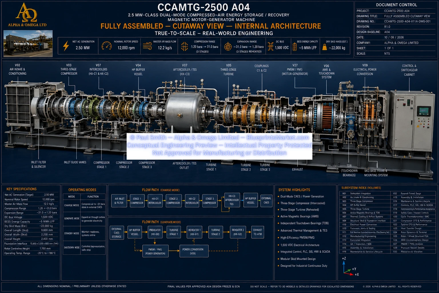
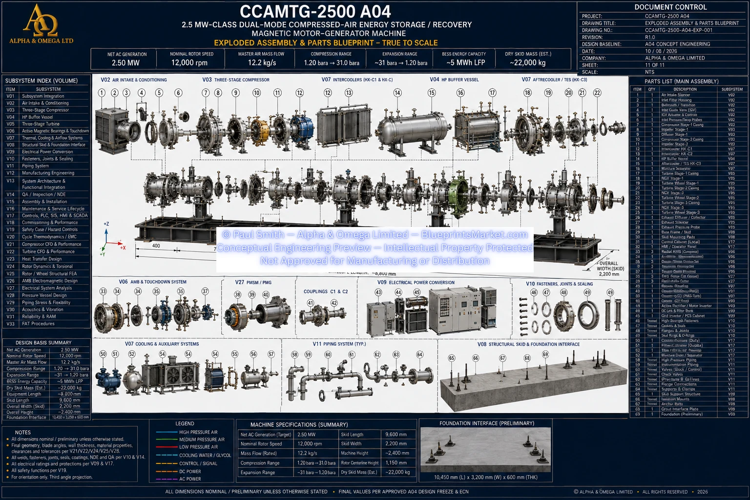
CCAMTG-2500 A04 — Full Machine Assembly & System Architecture
The CCAMTG-2500 A04 is a complete dual-mode compressed-air energy-storage and recovery machine integrating
multi-stage compression, thermal-energy recovery, high-pressure buffering, external compressed-air storage
interfacing, reheated turbine expansion, a common high-speed rotor train, active magnetic bearings, touchdown
bearings, a permanent-magnet motor-generator, bidirectional electrical power conversion, battery-energy-storage
and grid interfaces, cooling, instrumentation, structural support, controls, protection and machine safety systems.
Main Public Specifications
- Machine Class: 2.5 MW-Class Dual-Mode Compressed-Air Energy Storage / Recovery Magnetic Motor-Generator Machine
- Net AC Generation: 2.50 MW
- Nominal Rotor Speed: 12,000 rpm
- Master Air Mass Flow: 12.2 kg/s
- Compression Range: 1.20 bara → ~31 bara
- Expansion Range: ~31 bara → 1.20 bara
- DC Bus: 1,500 VDC
- BESS Energy Capacity: ~5 MWh LFP
- Dry Skid Mass (Estimated): ~22,000 kg
A04 Design Baseline:
Published specifications represent the current CCAMTG-2500 A04 design baseline.
Dimensions and preliminary engineering values remain subject to final confirmation
under the approved A04 design freeze.
Full Machine System Overview
- Dual-mode compressed-air energy storage and recovery architecture
- Three-stage centrifugal compressor system
- Three-stage reheated turbine system
- Common high-speed rotor train
- Permanent-magnet synchronous motor-generator
- Active magnetic bearing system
- Independent touchdown-bearing backup support
- Thermal-energy recovery and reuse
- High-pressure buffer vessel
- External compressed-air storage interface
- Bidirectional electrical power-conversion system
- Battery energy storage and grid interface
Charge-Mode Operation
- Electrical energy supplied through the approved grid and/or energy-storage path
- Bidirectional converter operates the PMSM/PMG in motor mode
- Motor torque drives the common rotor and three-stage compressor
- Compressed air passes through staged intercooling
- Recoverable compression heat is transferred into the thermal-energy system
- Final compressed air passes through the HP buffer and storage interface
- External compressed-air storage receives the charged pneumatic energy
Generation-Mode Operation
- Stored compressed air is supplied through the external storage interface
- High-pressure air passes through the HP buffer and turbine admission system
- Recovered thermal energy is used for turbine preheating and reheating
- Compressed air expands through three turbine stages
- Interstage reheating supports controlled staged expansion
- Turbine power drives the common rotor and PMSM/PMG in generator mode
- Generated electrical energy is routed to the BESS and/or grid interface
Standby & Transition Operation
- Magnetic-bearing levitation established before high-speed rotation
- Cooling and control power established before motoring
- Inactive high-pressure flow paths isolated
- Rotor speed actively controlled during operating transitions
- Electrical and pneumatic energy paths coordinated during mode changes
- Trip functions remove energy sources and manage safe rotor coast-down
Common Rotor Architecture
- Compressor, PMSM/PMG and turbine operate on the common rotor centreline
- Mechanically coupled sections share the same instantaneous shaft speed
- Modular rotor sections connected through high-speed diaphragm couplings
- Rotor modules designed for independent balancing and service access
- Thermal growth accommodated through the modular coupling architecture
- Rotor design coordinated with rotordynamic and torsional analysis
Three-Stage Compressor System
- Three sequential centrifugal compression stages
- Stage-specific impeller and diffuser assemblies
- Conditioned inlet and guide-vane architecture
- Staged pressure rise through the complete compressor train
- Intercooling between compressor stages
- Final aftercooling before storage interfacing
- Anti-surge recycle and protective control architecture
- Compressor casing and labyrinth sealing system
Thermal Recovery & Intercooling
- Heat removed after each compressor stage
- Recovered compression heat transferred to a separate thermal-energy loop
- Final aftercooler supports heat recovery before storage
- Thermal-energy storage interface supports later reuse during generation
- Thermal system coordinated with compressor and turbine operating states
High-Pressure Buffer System
- Local compressed-air flow-stabilization vessel
- Interfaces with compressor discharge
- Interfaces with external compressed-air storage
- Interfaces with the turbine admission path
- Provides pressure buffering and controlled operating transitions
- Provides isolation, relief and depressurization functions
- Includes pressure and temperature instrumentation
External Compressed-Air Storage Interface
- Long-duration compressed-air storage remains external to the machine skid
- Storage system connected through controlled high-pressure interfaces
- Fail-safe isolation incorporated into the storage connection
- Reverse-flow prevention incorporated into the interface
- Pressure control coordinated with independent protection functions
- Storage design remains site-specific
Three-Stage Turbine System
- Three sequential compressed-air expansion stages
- Dedicated nozzle guide vane assemblies for each stage
- Dedicated turbine wheel assemblies for each stage
- Preheating before the first turbine stage
- Reheating between successive turbine stages
- Progressive shaft-power recovery through the turbine train
- Diffuser and exhaust collector integration
- Labyrinth sealing throughout the turbine architecture
Active Magnetic Bearing System
- Non-contact radial rotor support
- Non-contact axial thrust control
- Multiple radial magnetic bearing stations
- Double-acting axial magnetic bearing architecture
- Continuous rotor-position monitoring
- Rotor speed and phase sensing
- Magnetic-bearing control integrated with machine protection
Touchdown Bearing System
- Mechanically independent backup rotor support
- Used during loss of magnetic levitation
- Supports controlled rotor coast-down during defined fault conditions
- Not used as the normal continuous running bearing system
- Integrated with rotor dynamics and machine protection
PMSM/PMG Motor-Generator
- High-speed permanent-magnet synchronous motor-generator
- Motor operation during compressed-air charging
- Generator operation during turbine-driven recovery
- Variable-frequency three-phase electrical interface
- Bidirectional power conversion
- Closed-loop thermal management
- Rotor retention and electromagnetic design integrated with the common rotor system
Electrical Power Conversion
- Machine-side bidirectional active rectifier and motor inverter
- Common DC power-distribution architecture
- Precharge and main isolation functions
- Continuous insulation monitoring
- Battery energy storage and PCS interface
- Grid-side inverter interface
- Transformer and switchgear integration
- Electrical metering and protection
Battery Energy Storage & Grid Integration
- Battery-energy-storage interface supports charging and generation modes
- Bidirectional PCS coordinates machine, battery and grid power flow
- Battery-management data integrated with the energy-management system
- Grid connection supports controlled import and export
- Transformer and switchgear configuration coordinated with the installation site
- Grid protection and synchronization governed by site-specific engineering
Machine Cooling System
- Closed-loop cooling for the motor-generator
- Cooling support for active magnetic bearing equipment
- Cooling interfaces for power electronics
- Cooling support for machine auxiliaries
- Redundant pumping philosophy
- Heat rejection, filtration and expansion management
- Flow, temperature, pressure and differential-pressure monitoring
Valve & Process Control Architecture
- Fail-safe external storage isolation
- Fail-safe turbine inlet control
- Compressor discharge isolation
- Protective anti-surge recycle
- Reheater isolation
- Independent buffer-vessel overpressure relief
- Controlled depressurization and blowdown
- Passive reverse-flow protection
Instrumentation & Monitoring
- Compressor inlet and discharge pressure monitoring
- Buffer-vessel pressure monitoring
- Main air-flow monitoring
- Compressor temperature monitoring
- Turbine preheat and reheat temperature monitoring
- Turbine outlet temperature monitoring
- Rotor vibration and position monitoring
- Redundant rotor-speed sensing
- Filter condition monitoring
- Condensate and drain monitoring where required
Control System & Operating Sequences
- Startup permissive verification before high-energy operation
- Magnetic-bearing levitation and centring before rotor acceleration
- Cooling availability verified before motoring
- Controlled DC-bus precharge
- Charge-mode sequencing with compressor anti-surge protection
- Generation-mode sequencing with turbine preheat and reheat
- Controlled transition between motoring and generation
- Integrated trip and shutdown hierarchy
Machine Protection & Trip Functions
- Overspeed protection
- Magnetic-bearing instability protection
- High-vibration protection
- High-pressure protection
- Cooling-failure protection
- Electrical-fault isolation
- Fire and emergency-stop response
- Controlled high-pressure isolation
- Controlled depressurization
- Safe rotor coast-down management
Structural Skid & Foundation Interface
- Integrated welded machinery skid
- Structural support for compressor, motor-generator and turbine modules
- Support interfaces for magnetic bearings and touchdown bearings
- Support interfaces for heat exchangers and cooling equipment
- Support interface for the HP buffer vessel
- Machinery mounting and alignment system
- Grout and anchor interface
- Lifting and transport provisions
- Site-specific foundation interface
Fasteners, Joints & Sealing
- Critical bolted-joint engineering
- Controlled fastener preload
- Pressure flange and gasket systems
- Compressor and turbine casing joints
- Rotating-component retention systems
- Structural mounting joints
- Labyrinth and static sealing systems
- Joint inspection and lifecycle traceability
System-Level Component Families
- Compressor module
- PMSM/PMG module
- Turbine module
- Radial active magnetic bearing assemblies
- Axial active magnetic bearing assembly
- Touchdown-bearing assemblies
- High-speed diaphragm couplings
- Compressor intercoolers
- Aftercooler and heat-recovery exchanger
- Turbine preheater
- Interstage reheaters
- HP buffer vessel
- Anti-surge recycle system
- High-pressure control and isolation valves
- Cooling package
- AMB controller and power amplifiers
- PLC, SIS and HMI systems
- Electrical conversion package
- Battery energy storage
- Grid transformer and switchgear
- Structural skid and guards
- Instrumentation
- External compressed-air storage interface
- Thermal-energy storage interface
Manufacturing & Quality Integration
- Controlled manufacturing documentation across all machine subsystems
- Traceable materials and critical components
- Subsystem-specific machining and fabrication controls
- Qualified welding and pressure-boundary procedures
- Critical rotor balancing and alignment controls
- Electrical and instrumentation verification
- Inspection and non-destructive examination
- Controlled assembly and installation records
Required Engineering Analysis
- Thermodynamic cycle modelling
- Compressor aerodynamic analysis
- Turbine aerodynamic analysis
- Heat-exchanger and thermal-energy-storage modelling
- Rotor dynamics
- Torsional analysis
- Rotor and wheel structural analysis
- Skid and foundation structural analysis
- Magnetic-bearing electromagnetic and stability analysis
- Motor-generator electromagnetic design
- Pressure-vessel code calculations
- Electrical protection and short-circuit analysis
- Hazard and safety analysis
- Site foundation and structural engineering
Safety Architecture
- Independent mechanical overpressure protection
- Fail-safe high-pressure isolation
- Protective compressor anti-surge architecture
- Redundant rotor-speed monitoring
- Magnetic-bearing fault management
- Touchdown-bearing fault support
- Electrical insulation and earthing protection
- Fire detection and emergency response integration
- Guarding of high-energy rotating and pressure-containing components
- Controlled depressurization before maintenance
Verification & Performance Acceptance
- Rotor-speed regulation verification
- Compressed-air flow verification
- Compressor performance verification
- Turbine performance verification
- Electrical generation verification
- Magnetic-bearing vibration verification
- Overspeed protection testing
- Anti-surge protection testing
- Pressure-protection verification
- Operating-mode transition verification
- Battery-energy-management interface testing
- Integrated factory and site acceptance testing
Master Design Rules
- Serial process-flow paths maintain mass-balance consistency
- Mechanically coupled rotor sections share one instantaneous shaft speed
- Every claimed output is tied to its defined energy source and conversion losses
- Mechanical, electrical and thermal power quantities remain clearly distinguished
- Pressure boundaries include controlled pressure, temperature, material and protection requirements
- High-speed rotor geometry remains subordinate to approved rotor and stress analysis
- Aerodynamic geometry remains subordinate to approved performance analysis
- Critical bolted joints receive controlled preload engineering
- Electrical systems receive coordinated voltage, current, fault and thermal verification
Full Machine Engineering Package
- Master Blueprint Document
- General arrangement and datum control
- Air-intake and conditioning engineering
- Three-stage compressor engineering
- HP buffer vessel engineering
- Three-stage turbine engineering
- Active magnetic bearing and touchdown-bearing engineering
- Thermal, cooling and airflow engineering
- Structural skid and foundation-interface engineering
- Electrical power-conversion engineering
- Fasteners, joints and sealing engineering
- Manufacturing engineering
- System architecture and functional integration
- QA, inspection and NDE
- Assembly and installation engineering
- Maintenance and service engineering
- Controls, PLC, SIS, HMI and SCADA
- Commissioning and performance acceptance
- Safety-case and hazard-control engineering
- Supporting calculation and analysis volumes