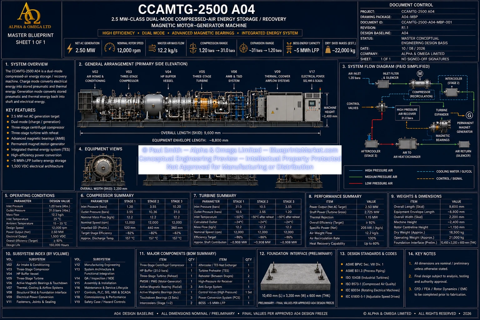
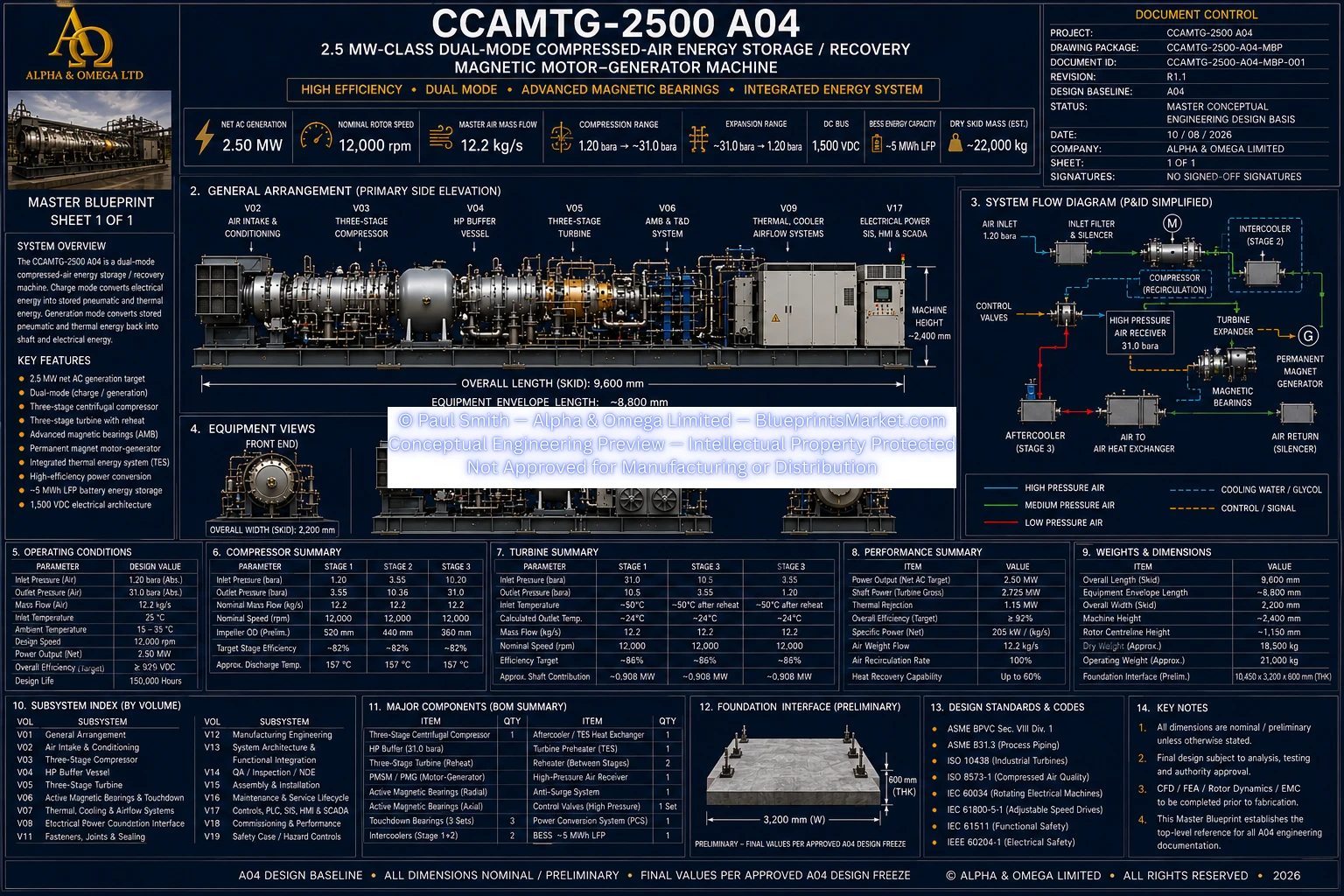
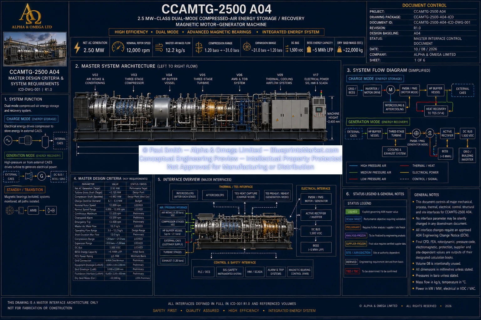
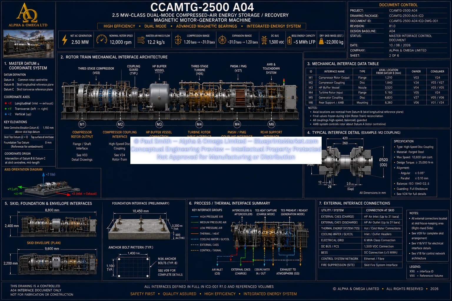
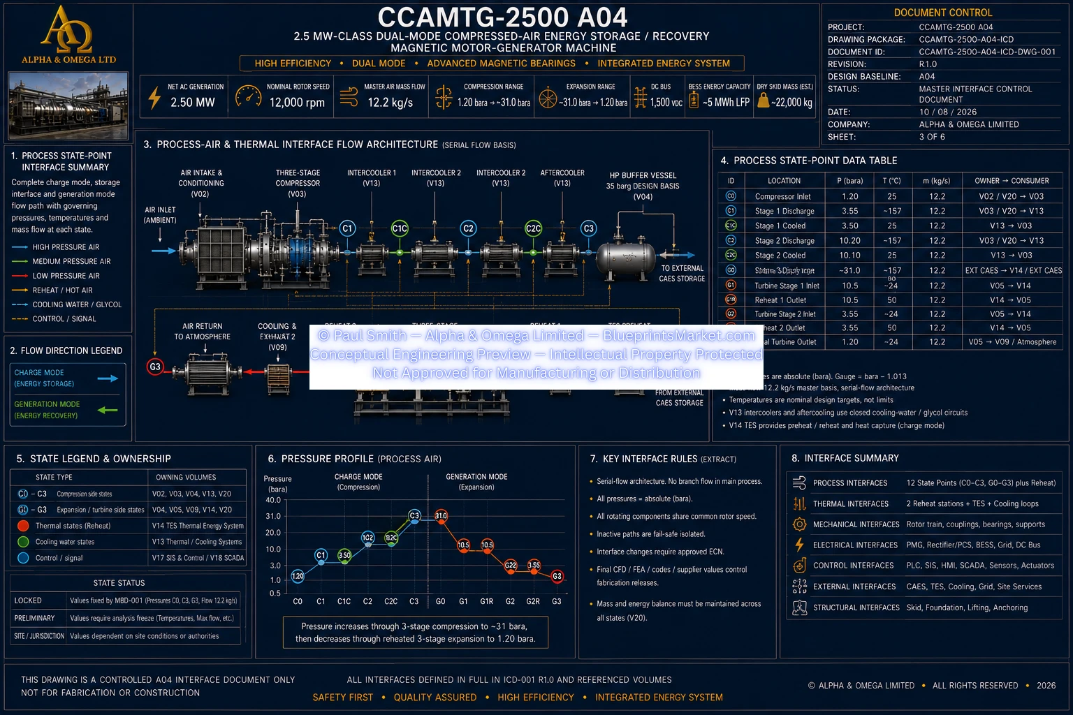
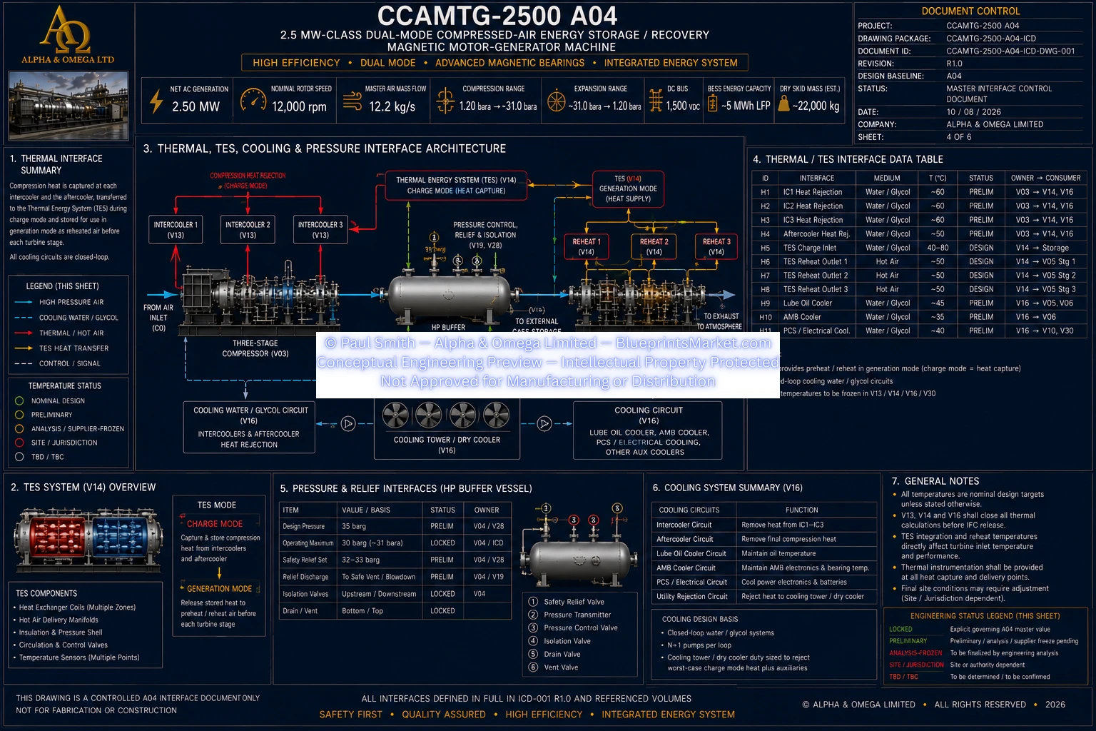
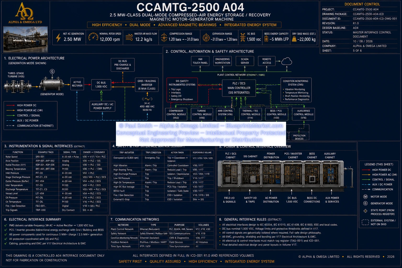
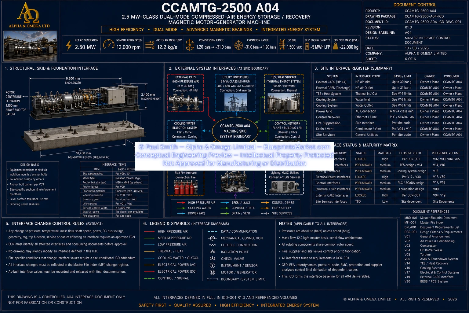
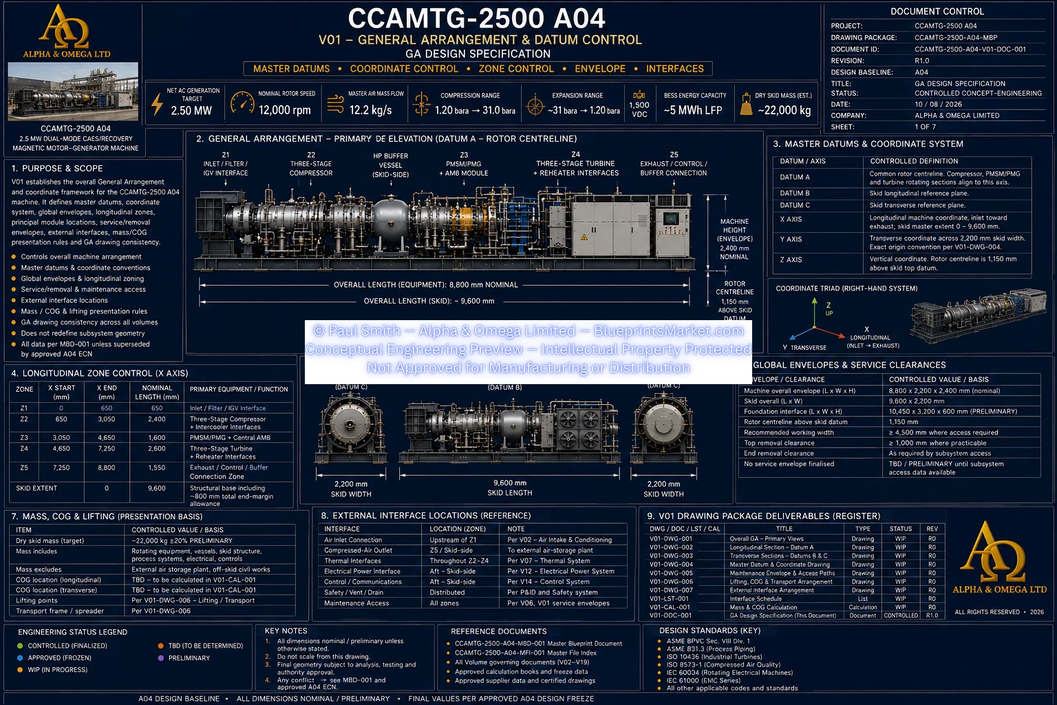
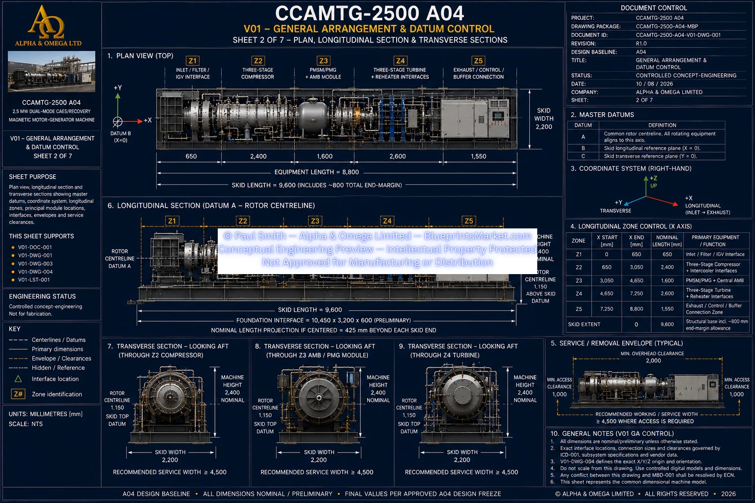
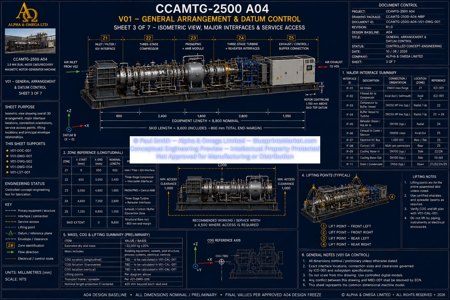
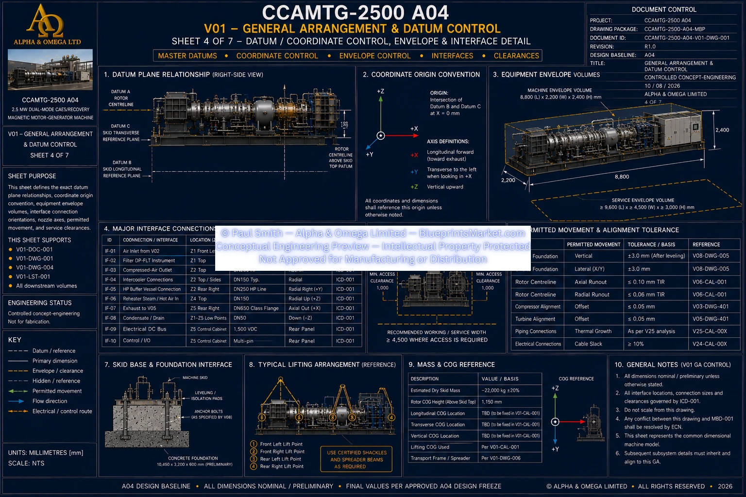
The CCAMTG-2500 A04 General Arrangement & Datum Control system establishes the master physical layout, machine envelope, rotor alignment framework, subsystem zoning, structural skid relationship, service-access philosophy and external interface coordination for the complete compressed-air energy storage and turbine-generator platform.
This V01 engineering volume provides the common dimensional and coordinate framework used throughout the CCAMTG-2500 A04 architecture. It ensures that the compressor, permanent-magnet motor-generator, active magnetic bearings, turbine, thermal systems, electrical systems, controls and structural interfaces remain coordinated around one consistent machine geometry.
The CCAMTG-2500 A04 is organized as an integrated industrial machinery package with a common high-speed rotor centreline and a coordinated structural skid. The General Arrangement defines how the principal mechanical, electrical and thermal modules are positioned relative to one another and how the complete machine interfaces with its installation environment.
One of the most important features of the CCAMTG-2500 A04 General Arrangement is the common rotor centreline used by the major rotating assemblies. The centrifugal compressor, permanent-magnet motor-generator and turbine are coordinated around the same primary mechanical axis.
This common alignment framework provides the reference needed to maintain consistent positioning across the rotating train and enables all associated subsystem drawings to reference one shared geometry instead of developing independent and potentially conflicting layouts.
The A04 General Arrangement uses a controlled datum system to establish a consistent engineering reference for every major module and interface. This allows mechanical, structural, thermal, electrical and controls documentation to reference the same machine coordinate framework.
This coordinated reference architecture supports consistent subsystem placement, machine alignment, external interface positioning and engineering drawing control across the CCAMTG-2500 A04 package.
The complete machine is organized into controlled longitudinal functional zones. Each zone corresponds to a major stage of the compressed-air and power-conversion process while remaining structurally integrated into the same machinery platform.
The compressor occupies the upstream rotating-machine section of the CCAMTG-2500 A04. Its three centrifugal compression stages are integrated with intercooling and thermal energy recovery interfaces while remaining aligned to the common machine rotor centreline.
The bidirectional permanent-magnet motor-generator is positioned centrally within the rotating-machine architecture. This arrangement allows the electrical machine to operate as a motor during compressed-air charging and as a generator during energy recovery.
The turbine occupies the downstream rotating-machine zone and is aligned directly with the same rotor datum used by the compressor and motor-generator. The three-stage turbine architecture supports controlled compressed-air expansion and electrical energy recovery.
The high-pressure buffer vessel forms part of the compressed-air interface between compression, storage and turbine operation. Its installation can be coordinated alongside the principal skid arrangement so that pressure-line routing, service access and structural requirements can be balanced without disrupting the main rotating-machine alignment.
The CCAMTG-2500 A04 General Arrangement is built around a coordinated industrial structural skid that supports the major rotating, thermal, electrical and auxiliary equipment. The skid establishes the primary machinery base and provides the interface between the packaged machine and its site-specific foundation.
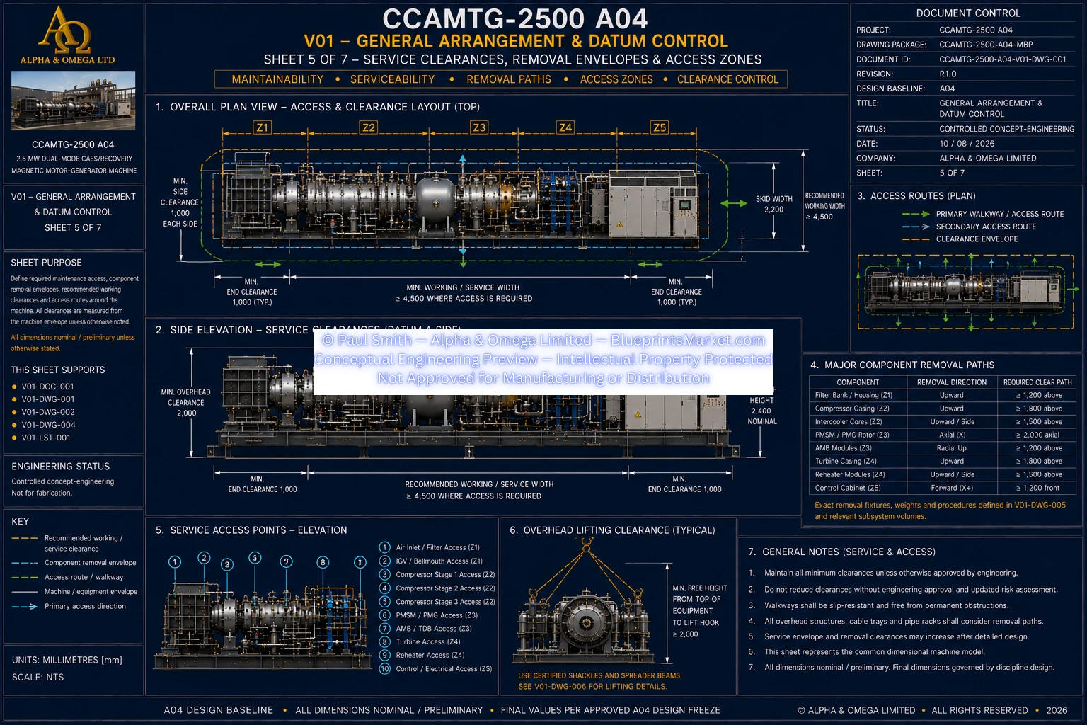
The General Arrangement also considers the space required to inspect, maintain and remove major machine components. Service access is treated as part of the overall engineering architecture rather than as an afterthought.
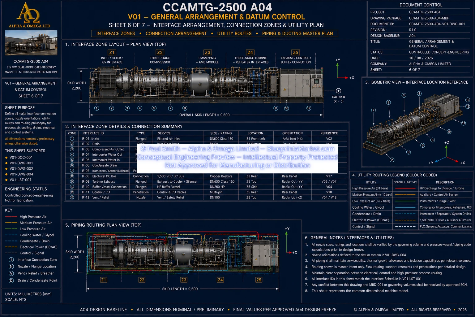
The General Arrangement coordinates the major external interfaces required to connect the CCAMTG-2500 A04 to compressed-air storage, thermal systems, electrical infrastructure, controls networks and site services.
The purpose of V01 is not to redesign the compressor, turbine, magnetic bearings, pressure vessel or electrical systems independently. Instead, it provides the common General Arrangement that keeps those engineering disciplines physically compatible with one another.
Each subsystem maintains its own detailed engineering authority while inheriting the master machine envelope, datum framework and integration rules established by the CCAMTG-2500 A04 General Arrangement.
The licensed CCAMTG-2500 A04 engineering package contains the coordinated General Arrangement drawing set and supporting engineering documentation required to understand the complete machine layout and how its principal systems relate to one another.
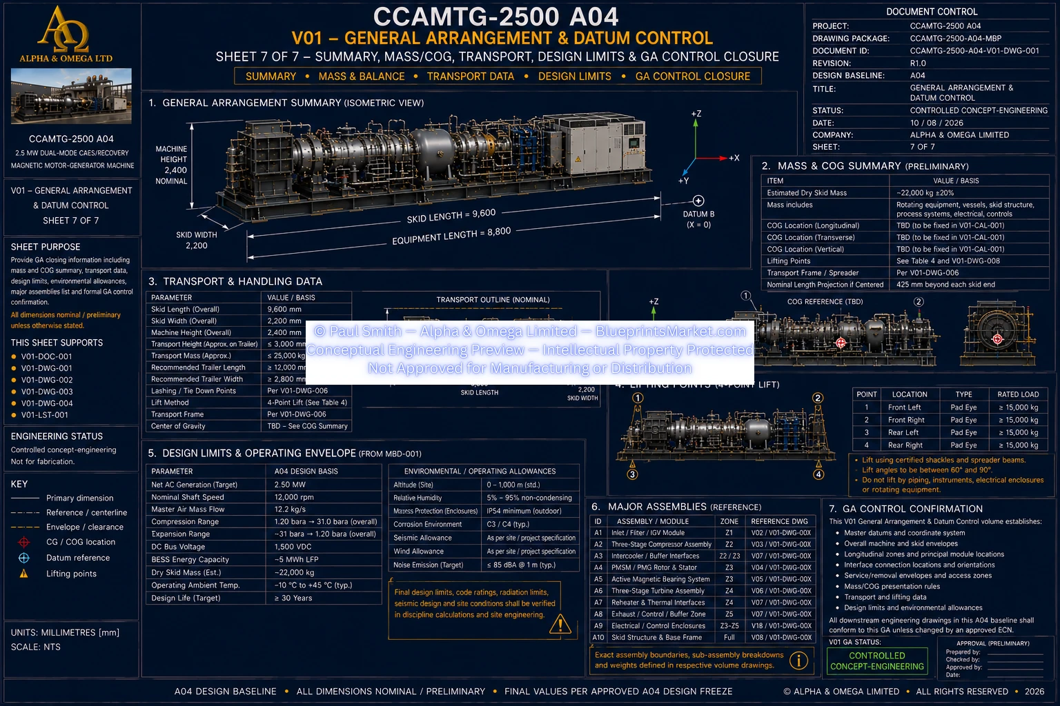
Detailed dimensional drawings, internal coordinates, controlled interface schedules, installation-specific geometry, engineering calculations, mass and centre-of-gravity information, lifting information and other controlled technical data remain within the licensed blueprint package.
A core principle of the CCAMTG-2500 A04 General Arrangement is that every view and subsystem must remain consistent with the same dimensional machine model. Components are not moved, stretched or repositioned simply to improve drawing presentation.
This provides a consistent engineering foundation for the complete A04 system and allows subsequent compressor, turbine, magnetic-bearing, thermal, electrical, manufacturing, installation and control documentation to reference one coordinated machine geometry.
The CCAMTG-2500 A04 General Arrangement & Datum Control package is a controlled concept-engineering design specification. It defines the governing machine envelope, master datum framework, subsystem zones and integration relationships at the A04 engineering maturity level.
Final fabrication, lifting, installation, supplier-specific geometry, pressure-system details and site foundation engineering remain subject to the applicable specialist calculations, supplier information, engineering design freezes and jurisdictional approval.
Continue through the CCAMTG-2500 A04 subsystem pages to explore the air intake, three-stage compressor, HP buffer vessel, turbine, magnetic bearings, thermal and cooling systems, structural skid, electrical power conversion, controls, system integration, manufacturing engineering, QA, assembly, maintenance, commissioning and safety architecture.