
1. Aerodynamic & Wind Engineering Design Basis
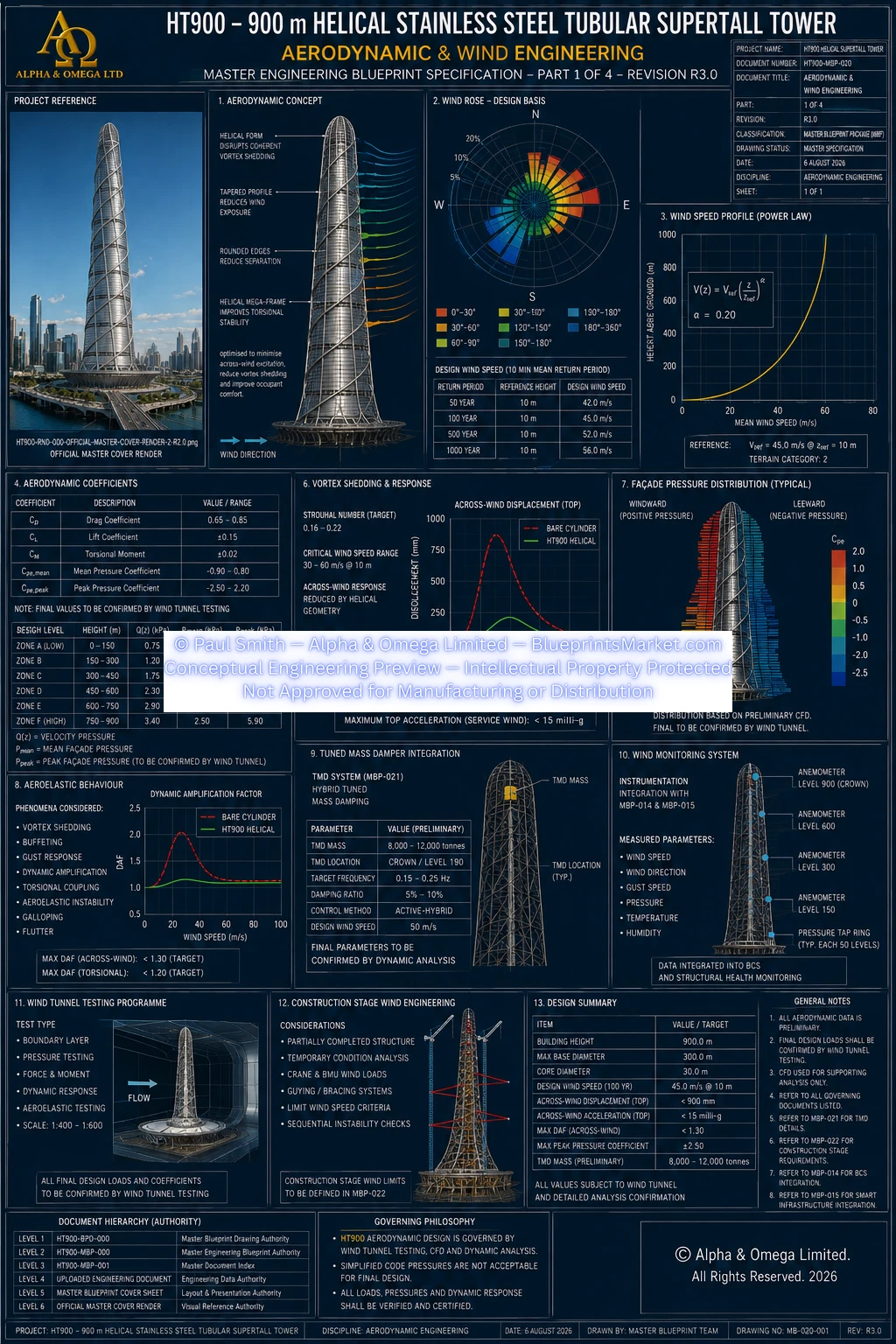
The HT900 R3.0 Aerodynamic & Wind Engineering system establishes the conceptual engineering framework for evaluating and controlling wind effects on the 900 metre Helical Stainless-Steel Tubular Supertall Tower.
The aerodynamic architecture is coordinated with the tower's global geometry, Exterior Helical Megaframe, Stainless Steel Tubular Core, Radial Floor Structural System, Outrigger & Belt-Truss System, Crown Dome Structure and Hybrid Tuned Mass Damping System.
Primary Engineering Objectives
- Minimise across-wind excitation
- Reduce coherent vortex-shedding excitation
- Reduce torsional response
- Improve structural serviceability
- Improve occupant comfort
- Reduce structural fatigue demand
- Reduce local peak façade pressures
- Improve crown aerodynamic behaviour
- Improve construction-stage wind stability
- Support long-term structural monitoring
Wind Engineering Philosophy
The HT900 R3.0 concept does not assign final tower wind loading through a single simplified uniform wind-pressure assumption.
Final project wind actions, façade pressures and dynamic response are intended to be established through site-specific meteorological assessment, physical wind-tunnel testing, computational analysis and integrated structural dynamic modelling during professional project development.
2. Master Aerodynamic Geometry
Aerodynamic behaviour is governed by the controlled HT900 R3.0 master tower geometry.
| Architectural Height | 900.0 metres |
|---|---|
| Structural Levels | 200 |
| Maximum Base Envelope Diameter | 300.0 metres |
| Maximum Base Envelope Radius | 150.0 metres |
| Perimeter Column Centreline Diameter | 270.0 metres |
| Central Stainless-Steel Tubular Core Diameter | 30.0 metres |
| Primary Structural Grid | 48 sectors |
| Primary Angular Spacing | 7.5° |
| Total Helical Rotation | 160° |
External Aerodynamic Form
- Continuously rotating helical tower geometry
- Progressively tapered external envelope
- Rounded external transitions
- Continuous Duplex Stainless Steel tubular megaframe
- Integrated Crown Dome Structure
- Coordinated façade geometry
- Continuous helical structural load paths
3. Helical Aerodynamic Strategy
The HT900 tower uses a controlled helical structural and architectural form that progressively rotates throughout the full tower height.
| Total Helical Rotation | 160° |
|---|---|
| Average Rotation per Structural Level | 0.8° |
| Average Twist Rate | Approximately 0.178° per metre |
Aerodynamic Intent
- Distribute aerodynamic loading around the tower envelope
- Reduce sustained coherent vortex formation
- Reduce across-wind excitation
- Improve torsional behaviour
- Improve aerodynamic stability
- Support occupant-comfort objectives
Final aerodynamic effectiveness remains subject to professional CFD analysis, wind-tunnel testing and aeroelastic verification.
4. Progressive Taper & Geometric Transition Strategy
The tower's taper is an integral part of the HT900 aerodynamic engineering philosophy rather than being solely an architectural feature.
The progressive reduction and transformation of the tower envelope is intended to reduce projected wind area with increasing elevation while maintaining continuous structural load paths.
Principal Aerodynamic Objectives
- Reduce overturning demand
- Reduce across-wind excitation
- Reduce local wind-pressure concentrations
- Improve structural efficiency
- Improve dynamic performance
- Improve façade performance
- Reduce fatigue loading
Principal Transition Zones
| Approximately 300 m | First major aerodynamic transition |
|---|---|
| Approximately 600 m | Second major taper transition |
| Approximately 810 m | Crown transition region begins |
| Approximately 868.5 m | Crown base region |
| 900.0 m | Crown apex |
5. Structural Aerodynamic Integration
HT900 R3.0 does not treat aerodynamic performance as an isolated façade function. The aerodynamic strategy is integrated directly with the primary structural systems.
Integrated Structural Systems
- Helical structural geometry
- Progressive tower taper
- Exterior Helical Tubular Megaframe
- 30 metre Stainless Steel Tubular Core
- Radial Floor Structural System
- Outrigger & Belt-Truss System
- Crown Dome Structure
- Hybrid Tuned Mass Damping System
- Coordinated façade geometry
- Structural Health Monitoring provisions
Structural Behaviour
- Improved lateral stiffness distribution
- Reduced torsional response
- Reduced wind-induced structural vibration
- Improved structural load redistribution
- Improved serviceability
- Coordinated core-to-perimeter structural coupling
The Outrigger & Belt-Truss System primarily provides structural coupling and increased stiffness. Dynamic response reduction is principally coordinated through the complete structural architecture and Hybrid Tuned Mass Damping System.
6. Vortex-Shedding Control
The HT900 aerodynamic form incorporates multiple complementary strategies intended to disrupt organised vortex formation and reduce the potential for sustained aerodynamic excitation.
Primary Mitigation Features
- 160° progressive helical rotation
- Progressive tower taper
- Rounded structural transitions
- Crown Dome geometry
- Changing projected tower width
- Continuous façade transitions
- Controlled structural stiffness variation
Engineering Objectives
- Disrupt organised vortex formation
- Reduce resonance potential
- Reduce dynamic amplification
- Improve occupant comfort
- Reduce long-term fatigue demand
7. Conceptual Structural Response Targets
The following values are HT900 R3.0 project performance targets. They are not certified performance guarantees and require confirmation through integrated structural and aerodynamic engineering.
| Serviceability Drift Target | ≤ 0.9 m |
|---|---|
| Ultimate Drift Target | ≤ 1.8 m |
| Occupied-Floor Acceleration Target | ≤ 15 milli-g |
| Hybrid TMD Response-Reduction Target | ≥ 30% |
Final structural response depends upon the site-specific wind climate, structural stiffness, structural damping, Tuned Mass Damper performance, occupancy conditions and complete structural dynamic model.
8. Wind Loading & Façade Pressure Engineering
Final HT900 wind loading is intended to be established through project-specific professional wind engineering rather than fixed generic pressure values published on the conceptual product page.
Wind Assessment Framework
- Regional wind-climate assessment
- Topographic assessment
- Terrain classification
- Atmospheric boundary-layer simulation
- Full 360° wind-direction assessment
- Oblique-wind assessment
- Along-wind loading
- Across-wind loading
- Torsional loading
- Local turbulence assessment
Façade Pressure Assessment
Final façade pressures are intended to be established through high-frequency pressure measurements and integrated wind-engineering analysis.
- Positive façade pressures
- Negative pressures and suction
- Edge and corner zones
- Crown pressures
- Local turbulence effects
- Maintenance-system wind loading
- Building Maintenance Unit operating conditions
9. CFD & Physical Wind-Tunnel Verification
Computational Fluid Dynamics is used as part of the HT900 aerodynamic development process to study tower airflow, pressure distribution, turbulence and wake behaviour.
CFD supports engineering development but does not replace physical wind-tunnel testing for final project verification.
Computational Analysis
- Mean wind-flow patterns
- Velocity distribution
- Turbulence intensity
- Pressure distribution
- Helical airflow interaction
- Flow separation
- Crown airflow behaviour
- Building wake characteristics
- Pedestrian-level wind environment
Physical Wind-Tunnel Programme
- Atmospheric boundary-layer simulation
- Directional wind assessment
- Global structural loading
- Dynamic loading
- Façade pressure measurement
- Base reaction assessment
- Torsional-response assessment
- Occupant-comfort assessment
- Pedestrian-level wind assessment
- Crown aerodynamic assessment
Aeroelastic Verification
Aeroelastic modelling evaluates the coupled interaction between aerodynamic forces and structural motion.
- Coupled wind-structure interaction
- Resonance behaviour
- Dynamic amplification
- Structural damping
- Along-wind response
- Across-wind response
- Torsional response
- Hybrid TMD effectiveness
10. Hybrid Tuned Mass Damping Integration
The aerodynamic engineering architecture is coordinated directly with the dedicated HT900 Hybrid Tuned Mass Damping System.
The Hybrid TMD is located within the upper crown region and forms part of the overall dynamic-response control strategy for the 900 metre tower.
Conceptual System Architecture
- Suspended pendulum mass system
- Sliding platform architecture
- Hydraulic damping
- Magnetic centring
- Structural support frame
- Structural monitoring
- Automatic tuning capability
Public Performance Objective
The governing conceptual project objective is at least 30% reduction in wind-induced structural response through the integrated Hybrid Tuned Mass Damping System, subject to final structural dynamic analysis and wind-tunnel verification.
Detailed mass, geometry, connection, actuator, tuning and control specifications remain within the applicable HT900 Master Blueprint Package technical documentation.
11. Crown Dome Aerodynamics
The HT900 Crown Dome is an integrated aerodynamic and structural termination of the tower rather than a purely decorative architectural feature.
Aerodynamic Functions
- Controlled airflow separation
- Reduced vortex formation
- Improved dynamic stability
- Reduced local pressure concentration
- Reduced local turbulence
- Improved aerodynamic continuity
Crown Integration
- Tapered elongated dome geometry
- Helical structural ribs
- Rounded structural transitions
- Continuous structural framing
- Hybrid TMD support interfaces
- Communications interfaces
- Maintenance-system interfaces
12. Wind Monitoring & Structural Health Monitoring
The HT900 conceptual architecture incorporates a permanent wind-monitoring system coordinated with the wider Building Management, Smart Infrastructure and Structural Health Monitoring architecture.
Monitoring Functions
- Wind-speed monitoring
- Wind-direction monitoring
- Atmospheric-pressure monitoring
- Temperature monitoring
- Structural acceleration monitoring
- Structural displacement monitoring
- Building torsional-response monitoring
- Crown movement monitoring
- Hybrid TMD performance monitoring
- Façade movement monitoring
- BMU operational monitoring
Typical Instrumentation
- Ultrasonic anemometers
- Wind-direction sensors
- Accelerometers
- Displacement sensors
- Tilt sensors
- Strain monitoring
- Temperature sensors
- Barometric-pressure sensors
- Structural vibration sensors
- TMD position monitoring
Detailed sensor quantities, exact locations, calibration requirements, communication architecture and installation specifications remain part of the detailed HT900 technical documentation and subsequent project-specific engineering.
13. Construction-Stage Wind Engineering
Wind behaviour during construction differs significantly from the aerodynamic response of the completed HT900 tower.
Temporary structural conditions therefore require independent construction-stage wind engineering.
Construction-Stage Assessment
- Partial-height tower conditions
- Temporary structural bracing
- Temporary cranes and lifting systems
- Incomplete façade conditions
- Open-floor conditions
- Progressive structural stiffness
- Temporary stability systems
- Weather-monitoring requirements
Final crane limits, lifting limits and temporary wind operating restrictions are to be established by the project construction engineering team using site-specific temporary-works and lifting studies.
14. Lifecycle Aerodynamic Engineering
Aerodynamic engineering continues beyond initial tower design through inspection, monitoring, maintenance and periodic engineering review.
Lifecycle Provisions
- Continuous wind monitoring
- Continuous structural monitoring
- Wind-sensor inspection and calibration
- Structural-movement verification
- Crown inspection
- Façade inspection
- Building Maintenance Unit inspection
- Hybrid TMD inspection and performance review
- Long-term dynamic-response trending
- Periodic occupant-comfort assessment
Primary Structural Design-Life Objective
| Primary Structural Design Life | 150 years |
|---|---|
| Structural Monitoring | Continuous |
| Wind Monitoring | Continuous |
| Electronic Monitoring Equipment | Planned lifecycle replacement |
15. System Integration
Principal Connected Systems
- Global Geometry
- Stainless Steel Tubular Core
- Radial Floor Structural System
- Exterior Helical Megaframe
- Helical Structural System
- Outrigger & Belt-Truss System
- Crown Dome Structure
- Exterior Façade & Envelope System
- Hybrid Tuned Mass Damping System
- Building Control System
- Smart Infrastructure
- Structural Health Monitoring
- Construction Sequencing
- Maintenance & Access Systems
16. Engineering Logic Summary
The HT900 R3.0 aerodynamic strategy uses multiple coordinated systems rather than relying on a single wind-control feature.
- The 160° helical geometry disrupts sustained coherent aerodynamic excitation.
- The progressive tower taper reduces projected wind area and modifies airflow interaction with increasing height.
- The Exterior Helical Megaframe, Stainless Steel Tubular Core, Radial Floor System and Outrigger & Belt-Truss System provide coordinated structural stiffness and load redistribution.
- The Crown Dome provides a controlled aerodynamic termination at the upper tower.
- The Hybrid Tuned Mass Damping System provides additional dynamic-response control.
- CFD, physical wind-tunnel testing, aeroelastic modelling and structural dynamic analysis provide the required project-specific verification framework.
- Permanent wind monitoring and Structural Health Monitoring provide long-term operational performance information.
17. Professional Engineering Notice
The HT900 Aerodynamic & Wind Engineering system forms part of the HT900 R3.0 conceptual Master Blueprint Package.
Information presented on this public page describes the principal aerodynamic engineering philosophy, major geometry, system architecture, conceptual performance targets and verification methodology.
Detailed aerodynamic calculations, complete engineering parameters, detailed component specifications, proprietary system configuration, complete monitoring architecture and implementation-level engineering information remain within the applicable HT900 technical documentation or must be developed during subsequent professional project engineering.
Final wind loads, façade pressures, dynamic response, occupant-comfort performance and construction-stage operating limits must be established through site-specific professional analysis, physical wind-tunnel testing, structural engineering, regulatory review and certification by appropriately qualified and licensed professionals.
Copyright — Alpha & Omega Limited
All blueprint files, CAD parameters, architectural concepts, engineering specifications, and written content are the exclusive intellectual property of Alpha & Omega Limited. No part of the Stainless‑Steel Skyscraper Blueprint Package may be reproduced, distributed, or adapted without written consent.
Licensing, Copyright & Patent Restrictions
This engineering system and all associated blueprint materials, CAD files, diagrams, schematics, dimensional tables, and technical narratives are licensed, not sold, and remain the exclusive intellectual property of Alpha & Omega Limited.
This product is not eligible for patenting by any purchaser, user, organization, or third party. Patent filings, provisional patents, utility models, derivative patents, reverse‑engineering for patent purposes, and intellectual property claims are strictly prohibited.
Redistribution, resale, sublicensing, public posting, dataset inclusion, or any form of unauthorized duplication of blueprint materials, CAD files, diagrams, or engineering concepts is strictly prohibited. No license tier grants ownership, patent rights, or rights to file for intellectual property protection.
All architectural & engineering systems are conceptual and require full professional engineering validation before any real‑world use, construction, prototyping, or structural implementation.
Full legal details are available in the Terms & Conditions .