
MEP Systems Integration
HT900 — Integrated Mechanical, Electrical, Plumbing, HVAC, Fire-Safety & Building-Service Architecture
1.0 System Overview
The HT900 MEP Systems Integration architecture coordinates the mechanical, electrical, plumbing, HVAC, fire-safety, communications, control and monitoring systems of the 900-metre Helical Stainless-Steel Tubular Supertall Tower.
Rather than treating individual building services as unrelated installations, the HT900 uses a coordinated three-dimensional infrastructure strategy in which vertical risers, horizontal distribution, mechanical plant, electrical distribution, fire-safety systems and digital controls are integrated with the building's structural geometry.
The principal vertical service routes are coordinated within the 30-metre-diameter Duplex Stainless-Steel Tubular Core, while horizontal services are distributed through coordinated structural and service zones at each level.
The primary structural core is entirely tubular stainless steel. The HT900 does not use a reinforced-concrete primary structural core.
2.0 Governing Building Baseline
| Architectural Height | 900 m |
|---|---|
| Structural Levels | 200 |
| Typical Floor-to-Floor Height | 4.5 m |
| Maximum Building Envelope Diameter | 300 m |
| Structural Core | 30 m Duplex Stainless-Steel Tubular Core |
| Primary Structural Grid | 48 sectors |
| Primary Structural Material | Duplex Stainless Steel EN 1.4462 |
| Primary Structural Design Life | 150 years |
All MEP systems are coordinated around these governing structural dimensions and may not compromise the primary tubular stainless-steel structural system.
3.0 Integrated MEP Architecture
The complete MEP platform combines several independently engineered but fully coordinated building-service systems.
Mechanical & Hydraulic Systems
- Potable cold-water distribution
- Domestic hot-water generation and circulation
- Non-potable water distribution
- Greywater collection, treatment and reuse
- Chilled-water systems
- Condenser-water systems
- Pumping systems
- Water treatment
- Pressure-control systems
- Leak detection
Drainage Systems
- Sanitary drainage
- Blackwater drainage
- Stormwater drainage
- Condensate collection
- Plant-room drainage
- Façade drainage interfaces
- Foundation drainage
- Isolation-system drainage
HVAC & Environmental Control
- Chilled-water production
- Heating
- Fresh-air supply
- Return-air systems
- Exhaust-air systems
- Environmental control
- Humidity management
- Air-quality monitoring
- Energy recovery
Electrical Systems
- Utility power intake
- Primary electrical distribution
- Zone substations
- Low-voltage distribution
- Essential-services power
- Emergency generation
- UPS-supported critical systems
- Earthing and bonding
- Lightning protection
- Power monitoring
Fire & Life Safety Interfaces
- Fire-water distribution
- Automatic suppression interfaces
- Fire detection and alarm
- Smoke-management systems
- Stair and shaft pressurisation
- Emergency power
- Emergency communications
- Refuge-floor services
- Fire Command Centre interfaces
4.0 Tubular Core Service Routing
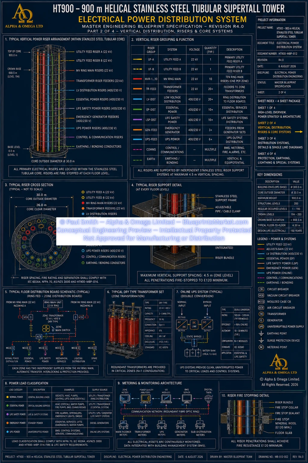
Principal vertical MEP routes are coordinated within the 30-metre circular Duplex Stainless-Steel Tubular Core.
These protected vertical service zones may include:
- Potable-water risers
- Domestic hot-water risers
- Hydronic risers
- Drainage and vent stacks
- Condensate risers
- Fire-water routes
- Electrical risers
- Emergency-power routes
- Control-system risers
- Communications pathways
- HVAC shafts
- Smoke-exhaust shafts
Core service routing is coordinated with elevators, protected emergency stairs, structural diaphragms, vertical stiffeners and maintenance corridors.
Routing services inside the core does not mean that any water, hydronic or other pressurised system operates as one uninterrupted 900-metre vertical circuit.
5.0 Structural & MEP Coordination
Building services are designed around the primary structure rather than cutting through it after construction.
No mechanical pipe, electrical route, duct, drain, cable system or service support is permitted to drill, cut or otherwise modify a primary tubular structural member.
Service routes are coordinated with:
- 30 m Tubular Stainless-Steel Core
- 48-sector radial floor structure
- Concentric structural rings
- Exterior Helical Megaframe
- Outrigger structures
- Belt-truss systems
- Structural node locations
- Façade support zones
- Fire compartment boundaries
- Maintenance and replacement routes
6.0 Floor-Level Service Distribution
Horizontal MEP distribution occurs within coordinated floor structural and service zones.
Depending on the individual service, distribution may use:
- Radial mains
- Sector mains
- Ring mains
- Looped distribution
- Local manifolds
- Electrical busway branches
- Cable routes
- Air-distribution branches
- Local distribution boards
- Floor-sector isolation systems
The final arrangement is determined through coordinated structural, hydraulic, mechanical, electrical, fire-safety and BIM engineering.
7.0 Multi-System Zoning Strategy
A 900-metre building cannot practically operate every building service as one unrestricted full-height system.
The HT900 therefore uses multiple coordinated but independently engineered service zones.
| Mechanical / Hydraulic Concept | Approximately 20 service zones |
|---|---|
| Primary HVAC Zones | 10 |
| Primary Electrical Zones | 10 |
| Fire & Life Safety Zoning | Independently engineered and coordinated |
| Control / Supervisory Architecture | Distributed zone-based architecture |
These zone boundaries do not have to be identical. Mechanical, hydraulic, electrical, HVAC, fire, smoke-control and evacuation zoning are designed according to the engineering requirements of each individual system.
8.0 Mechanical, Plumbing & Drainage Integration
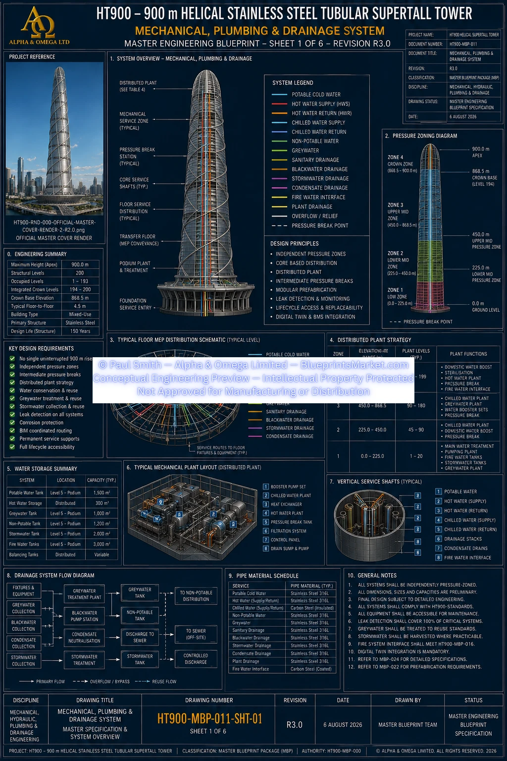
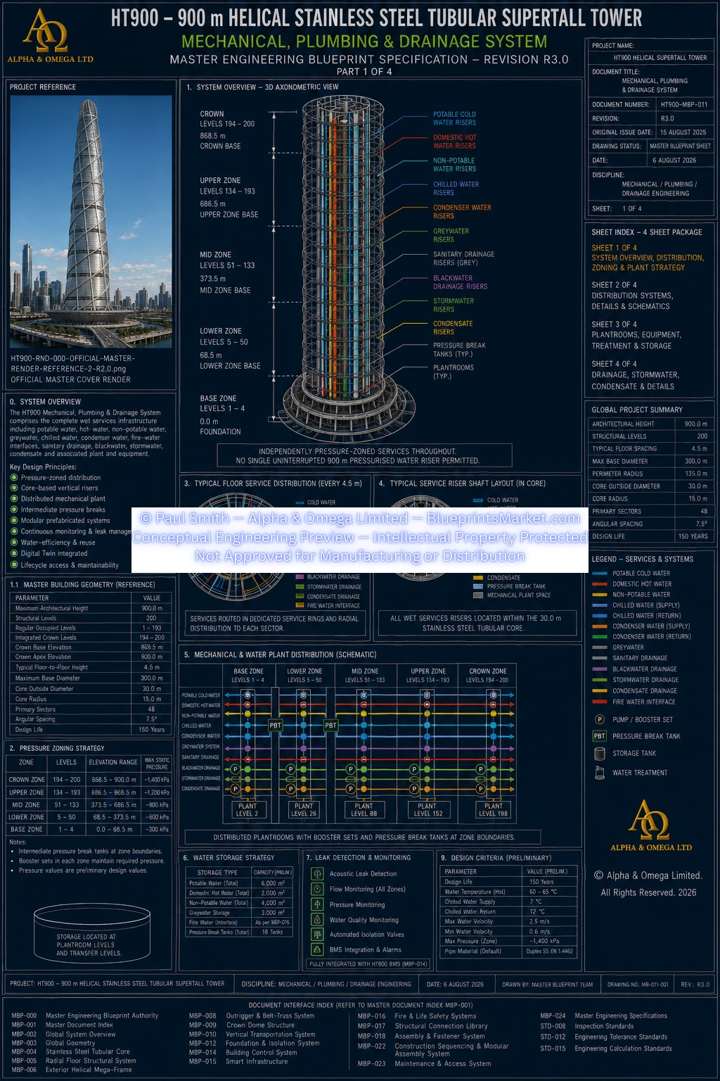
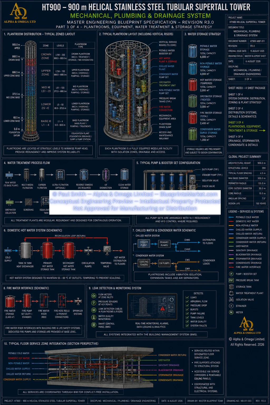
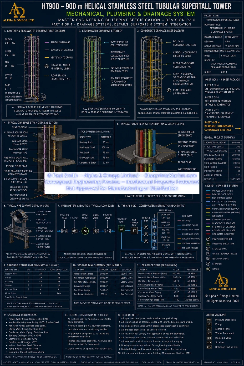
Wet mechanical systems use service-specific hydraulic zoning with intermediate pressure management rather than one universal pressure schedule.
The architecture incorporates:
- Zone-based potable-water distribution
- Domestic hot-water circulation
- Hydronic pressure-break systems
- Distributed pumping
- Water-treatment systems
- Water storage where required
- Greywater recovery and reuse
- Leak detection
- Hydraulic monitoring
- Engineered gravity drainage
No single uninterrupted 900-metre pressurised water riser is used.
Domestic water, hydronic systems, drainage and fire-water systems each use zoning appropriate to their own operating requirements.
9.0 HVAC & Environmental Control Integration
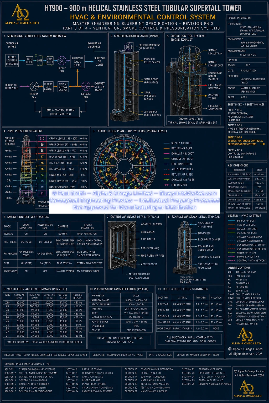
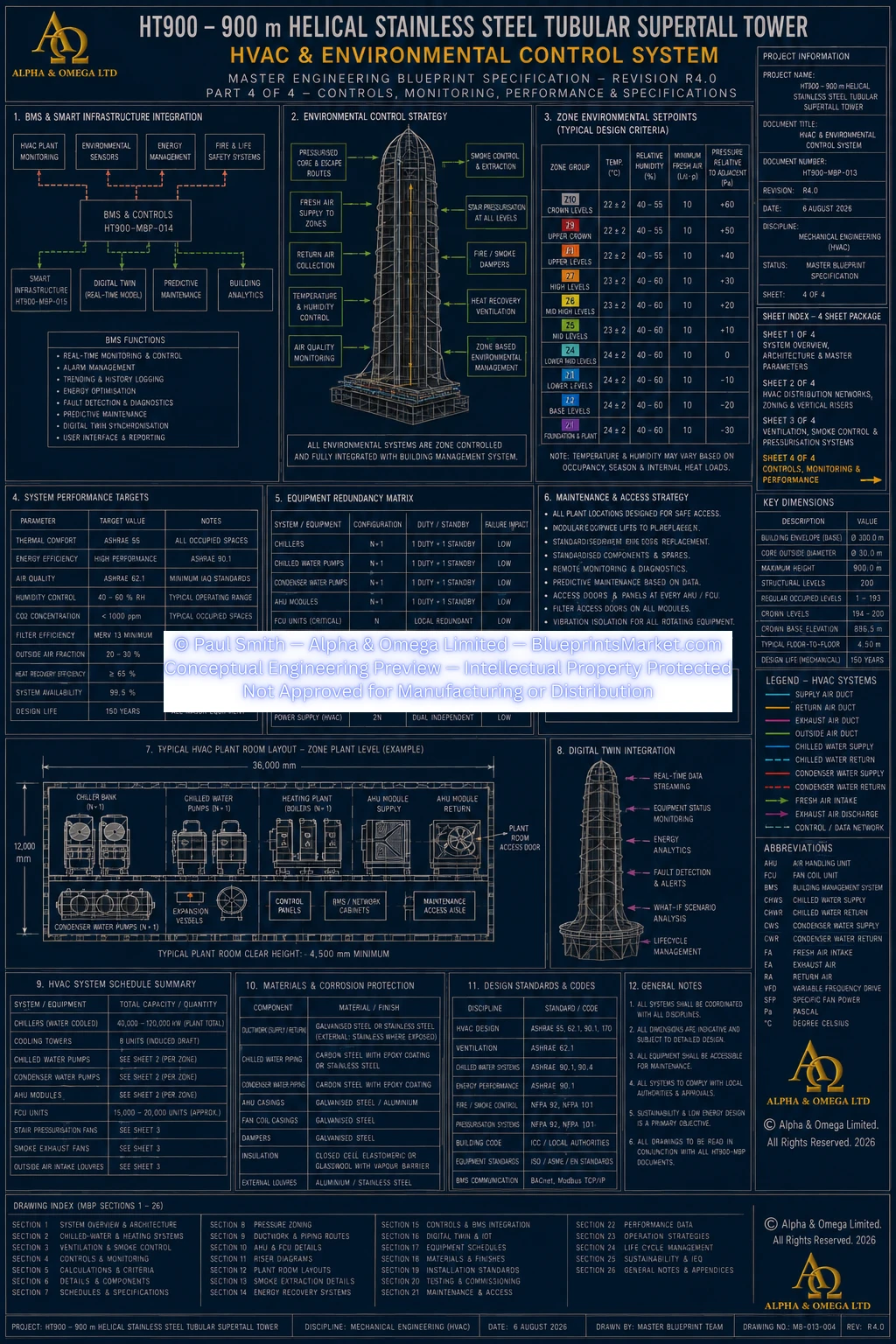
The HT900 environmental-control architecture combines central chilled-water production with distributed air-handling and pressure-zoned environmental control.
The tower is conceptually divided into ten primary HVAC pressure zones, allowing each major vertical section to operate independently while remaining coordinated through the Building Management System.
Primary HVAC Systems
- Central chilled-water plant
- Distributed chilled-water pumping
- Condenser-water systems
- Air Handling Units
- Fresh-air systems
- Return-air systems
- Exhaust-air systems
- Heating systems
- Energy recovery
- Environmental monitoring
Major mechanical plant is distributed vertically to reduce excessive pressure, pumping energy, fan energy, maintenance travel and system downtime.
10.0 Mechanical Distribution & Service Levels
Mechanical distribution functions occur at selected levels throughout the tower and are coordinated where practical with major structural, transportation and service-transfer zones.
These levels may support:
- Pressure-break stations
- Hydronic distribution
- Air-handling equipment
- Pumping systems
- Heat exchangers
- Electrical distribution
- Building-control equipment
- Smart Infrastructure nodes
- Maintenance facilities
- Service-transfer systems
The conceptual organisation places major service functions at intervals of approximately twenty structural levels where appropriate, but this does not mean every such level contains an identical mechanical plant arrangement.
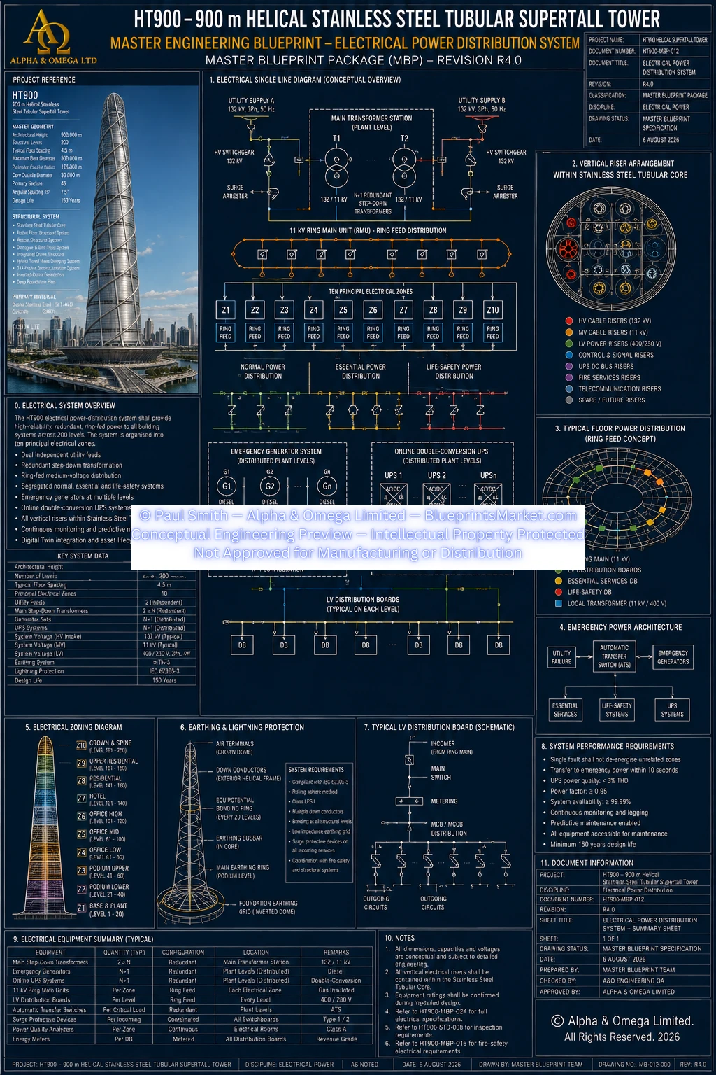
11.0 Electrical Power Integration
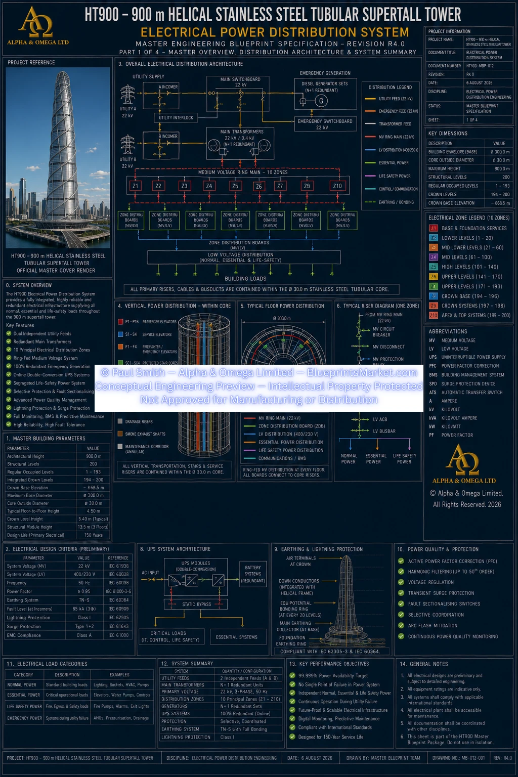
The HT900 electrical architecture is designed around redundancy, sectionalisation, fault containment and distributed power conversion.
Primary Electrical Architecture
- Two independent utility supply paths
- Redundant primary transformation
- Ten principal electrical distribution zones
- Ring-fed medium-voltage distribution
- Distributed substations
- Segregated normal and essential services
- Independent emergency generation
- UPS-supported critical systems
- Selective protection and fault isolation
- Continuous power monitoring
Principal electrical risers remain within the tubular stainless-steel core and distribute power into zone and floor-level electrical systems.
A single local electrical fault is not intended to unnecessarily de-energise the complete tower or unrelated distribution zones.
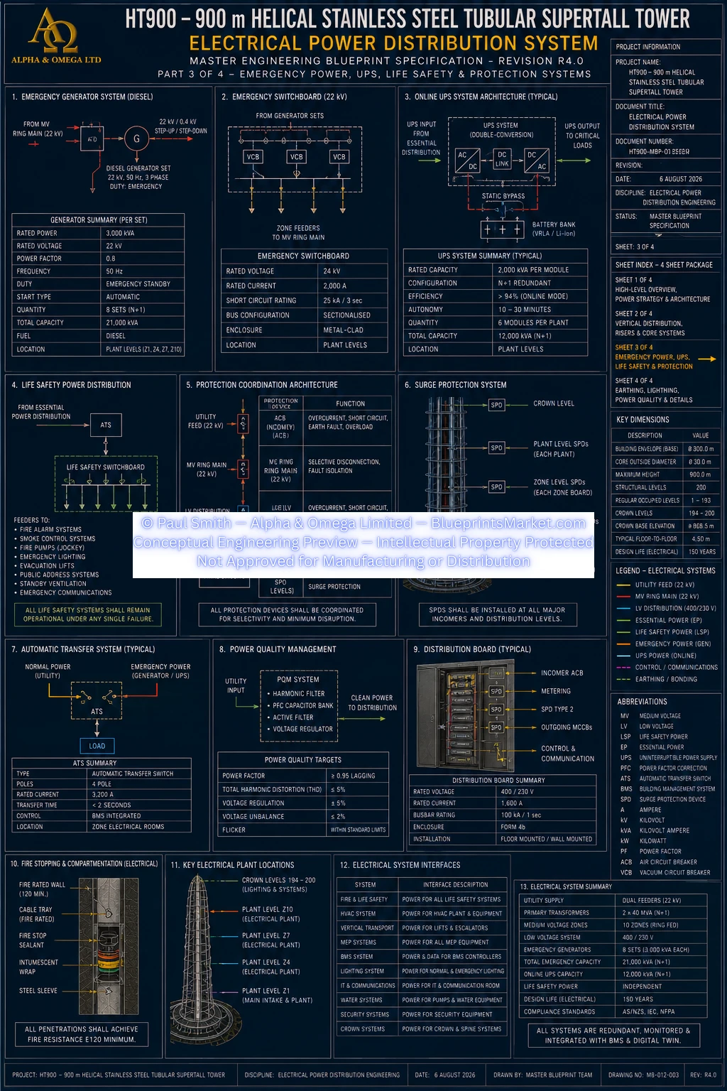
12.0 Emergency & Essential Power
Emergency electrical infrastructure is segregated from normal building loads and supports critical operational and life-safety systems.
The conceptual hierarchy includes:
- Normal utility power
- Emergency generator supply through automatic transfer systems
- UPS or battery no-break support for selected critical systems
- Dedicated life-safety power distribution
Essential loads may include:
- Fire detection and alarm
- Emergency communications
- Smoke-control systems
- Stair pressurisation
- Fire pumps
- Emergency lighting
- Firefighter elevators
- Critical building controls
- Communications infrastructure
- Structural Health Monitoring
13.0 Fire & Life Safety Integration
Fire engineering is integrated with the MEP architecture while remaining an independently certified life-safety discipline.
Coordination includes:
- Fire-water distribution
- Fire pumps and water storage
- Automatic suppression
- Fire-alarm interfaces
- Smoke extraction
- Stair and shaft pressurisation
- Emergency electrical distribution
- Emergency communications
- Firefighter elevator services
- Fire Command Centres
- Refuge-floor systems
Fire-water pressure zones, smoke-control zones, fire compartments, evacuation zones and HVAC zones are coordinated but are not assumed to be identical.
14.0 Smoke-Control & HVAC Interface
Smoke-control systems form a critical interface between HVAC engineering and the Fire & Life Safety System.
The strategy may include:
- Mechanical smoke extraction
- Controlled make-up air
- Pressurised emergency stairs
- Protected elevator lobbies
- Refuge-floor smoke protection
- Fire and smoke dampers
- Post-fire purge systems
Smoke-control equipment performance is established through project-specific fire modelling and certified equipment performance rather than one universal airflow, temperature or pressure requirement.
15.0 MEP Penetrations & Fire Compartmentation
Every MEP route crossing a rated fire or smoke boundary must preserve the required compartment performance.
Certified firestop systems are coordinated at:
- Pipe penetrations
- Electrical cable penetrations
- Duct penetrations
- Conduit routes
- Service shafts
- Structural interfaces
- Movement joints
- Façade interfaces
Firestopping and cavity barriers remain accessible for inspection, maintenance, repair and lifecycle certification.
16.0 Building Control System Integration
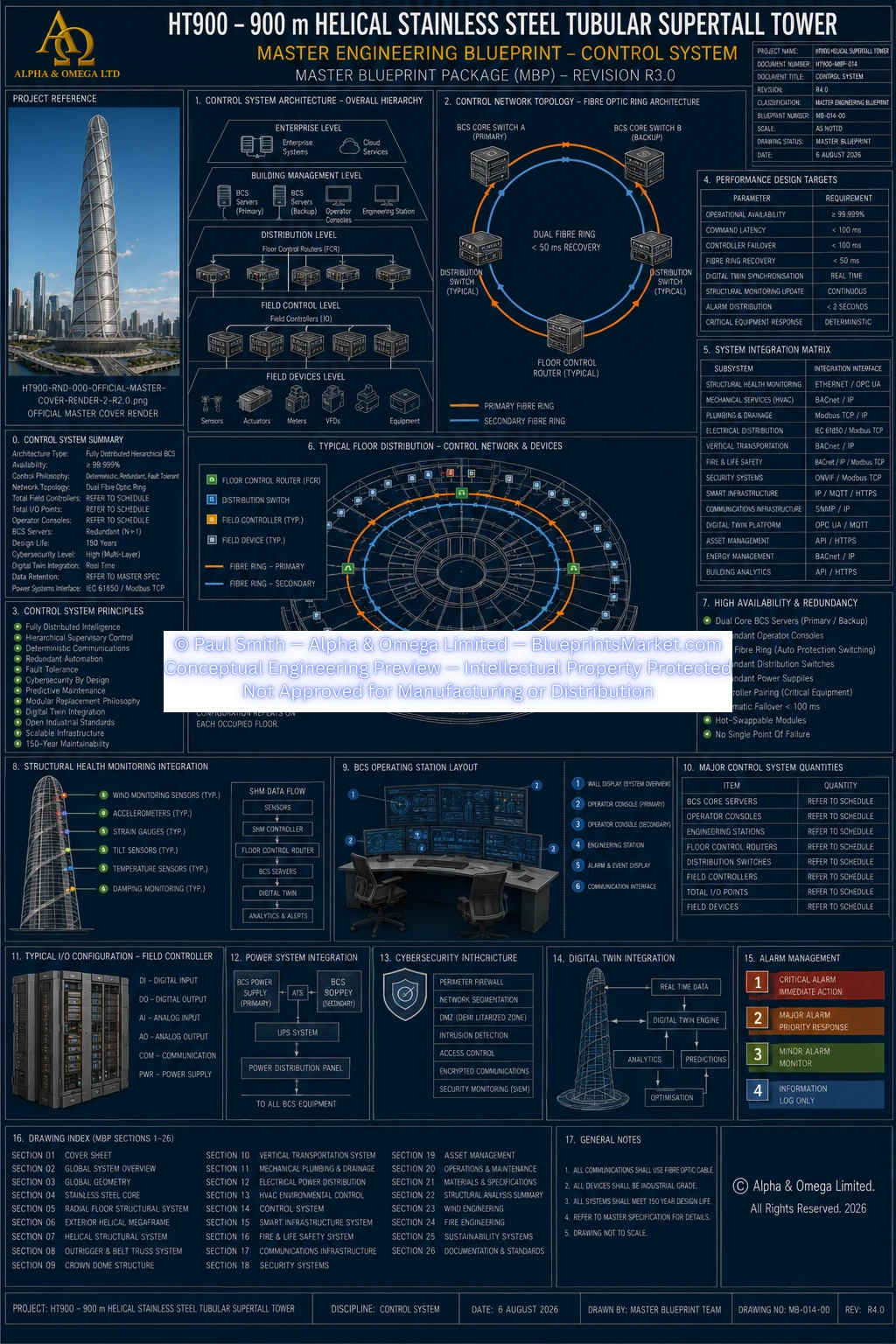
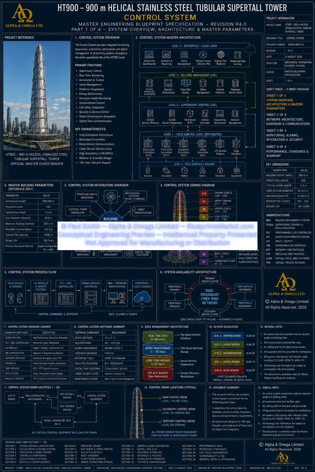
Mechanical and electrical plant is coordinated through the HT900 Building Control System while safety-critical equipment retains the required independent local controls.
Supervisory functions may include:
- HVAC operation
- Plant sequencing
- Pump control
- Pressure monitoring
- Water monitoring
- Energy monitoring
- Electrical status
- Environmental monitoring
- Equipment condition monitoring
- Fault reporting
The general Building Control System does not replace certified fire-alarm systems, emergency-stop systems, protective electrical relays or dedicated machinery safety controls.
17.0 Smart Infrastructure & Digital Twin
MEP systems are integrated into the HT900 Smart Infrastructure and Digital Twin environment for monitoring, maintenance and lifecycle engineering.
Digital integration may provide:
- Real-time equipment status
- Energy monitoring
- Water-use monitoring
- Environmental monitoring
- Leak detection
- Fault diagnostics
- Predictive maintenance
- Asset identification
- Inspection records
- Maintenance history
- Replacement forecasting
- Performance trending
Essential safety systems remain capable of operating independently if general Smart Infrastructure or Digital Twin services become unavailable.
18.0 Resilience & Redundancy
The MEP architecture uses distributed plant, zoning, redundancy and fault isolation to improve building resilience.
Depending on the individual system, resilience measures may include:
- Multiple service zones
- Redundant pumps
- Redundant HVAC plant
- Redundant electrical supplies
- Ring-fed electrical distribution
- Emergency generators
- UPS systems
- Multiple communications paths
- Independent life-safety systems
- Local isolation
- Fault sectionalisation
- Maintenance bypass arrangements where appropriate
19.0 Maintainability & Component Replacement
MEP equipment is designed around a lifecycle strategy that separates permanent service infrastructure from equipment intended for planned replacement.
Long-Life Infrastructure
- Principal service shafts
- Core service zones
- Structural service supports
- Major distribution pathways
- Permanent equipment-support interfaces
- Protected service penetrations
Replaceable Operational Equipment
- Pumps
- Valves
- Chillers
- Air Handling Units
- Fans
- Heat exchangers
- Transformers
- Switchgear
- UPS equipment
- Batteries
- Generators
- Control equipment
- Sensors
Replacement timing is governed by equipment condition, manufacturer requirements, operating duty, inspection results and lifecycle engineering.
20.0 Maintenance Access & Serviceability
MEP design is coordinated with dedicated maintenance corridors, service elevators, equipment galleries, access panels and component-replacement routes.
Major plant areas are designed to support:
- Routine servicing
- Equipment isolation
- Inspection
- Testing
- Component removal
- Replacement equipment delivery
- Temporary lifting
- Safe technician access
Maintenance access is coordinated so it does not compromise protected emergency routes or primary structural systems.
21.0 Modular Construction Philosophy
The HT900 MEP architecture supports prefabricated and modular installation wherever appropriate.
Modular systems may include:
- Service riser modules
- Pipework assemblies
- Valve and manifold assemblies
- Electrical distribution assemblies
- Cable-support systems
- Mechanical plant skids
- Control panels
- Service-floor distribution assemblies
Modularisation improves fabrication quality, installation coordination, testing and future replacement.
22.0 Integrated Testing & Commissioning
MEP systems require both individual-system commissioning and multidisciplinary integrated testing.
Testing may verify interaction between:
- Mechanical systems
- Plumbing and hydraulic systems
- HVAC
- Electrical power
- Emergency power
- Fire alarm
- Smoke management
- Fire pumps
- Emergency communications
- Vertical transportation
- Building controls
- Smart Infrastructure
- Structural Health Monitoring
Integrated commissioning verifies that the individual disciplines operate correctly together during normal operation, equipment failure, utility loss and emergency conditions.
23.0 Multidisciplinary Coordination
The MEP architecture is coordinated with every major HT900 structural and operational system.
Structural Interfaces
- Stainless-Steel Tubular Core
- Radial Floor Structural System
- Exterior Helical Megaframe
- Outrigger & Belt-Truss System
- Crown Dome Structure
- Foundation & Isolation System
Building-System Interfaces
- Mechanical, Plumbing & Drainage
- HVAC & Environmental Control
- Electrical Power Distribution
- Fire & Life Safety
- Vertical Transportation
- Building Control System
- Smart Infrastructure
- Structural Health Monitoring
- Maintenance & Access
- Digital Twin Infrastructure
This coordinated approach prevents individual building-service disciplines from being designed independently of the overall tower architecture.
24.0 Engineering Summary
The HT900 MEP Systems Integration architecture provides the coordinated building-service framework for the complete 900-metre tubular stainless-steel tower.
Wet services use pressure-zoned vertical distribution; HVAC uses ten principal pressure zones; electrical infrastructure uses ten principal distribution zones; fire and smoke systems use independently engineered life-safety zoning; and all systems are linked through coordinated control, monitoring and Digital Twin infrastructure.
Principal vertical services are integrated within the 30-metre Duplex Stainless-Steel Tubular Core while horizontal distribution follows the 48-sector structural floor architecture.
Distributed plant, intermediate pressure management, electrical sectionalisation, emergency power, modular service infrastructure and lifecycle access combine to create a highly integrated and maintainable building-services platform.
25.0 Conceptual Engineering Notice
This public page presents the high-level architecture and multidisciplinary engineering philosophy of the HT900 MEP Systems Integration system.
Detailed pipe diameters, duct dimensions, pressure ratings, equipment capacities, plant quantities, electrical voltages, cable and busbar schedules, hydraulic calculations, pump duties, HVAC equipment schedules, fire-hydraulic data, electrical fault calculations, equipment-room layouts, support geometry and other implementation-level specifications are contained within the licensed HT900 Master Blueprint Package and are intentionally not reproduced on this public overview page.
Any real-world implementation would require complete project-specific mechanical, hydraulic, electrical, HVAC and fire engineering; coordinated BIM modelling; load and demand calculations; equipment selection; utility coordination; integrated commissioning; regulatory approval; and certification by appropriately qualified and licensed engineering professionals.
HT900-MBP-011 — MECHANICAL, PLUMBING & DRAINAGE SYSTEM

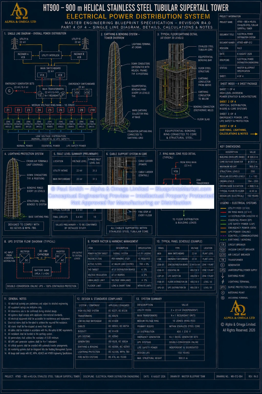
HT900-MBP-012 — ELECTRICAL POWER DISTRIBUTION SYSTEM
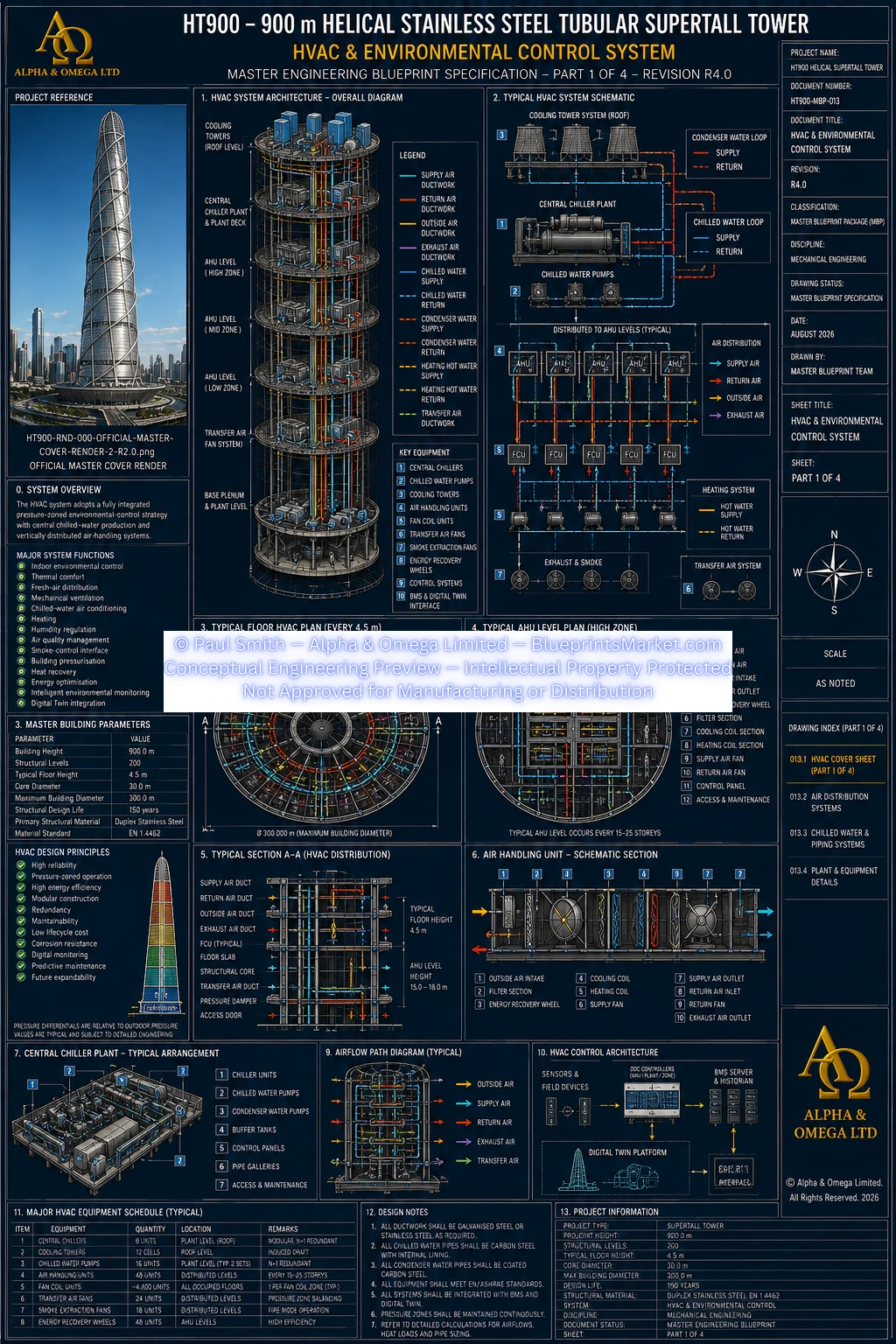
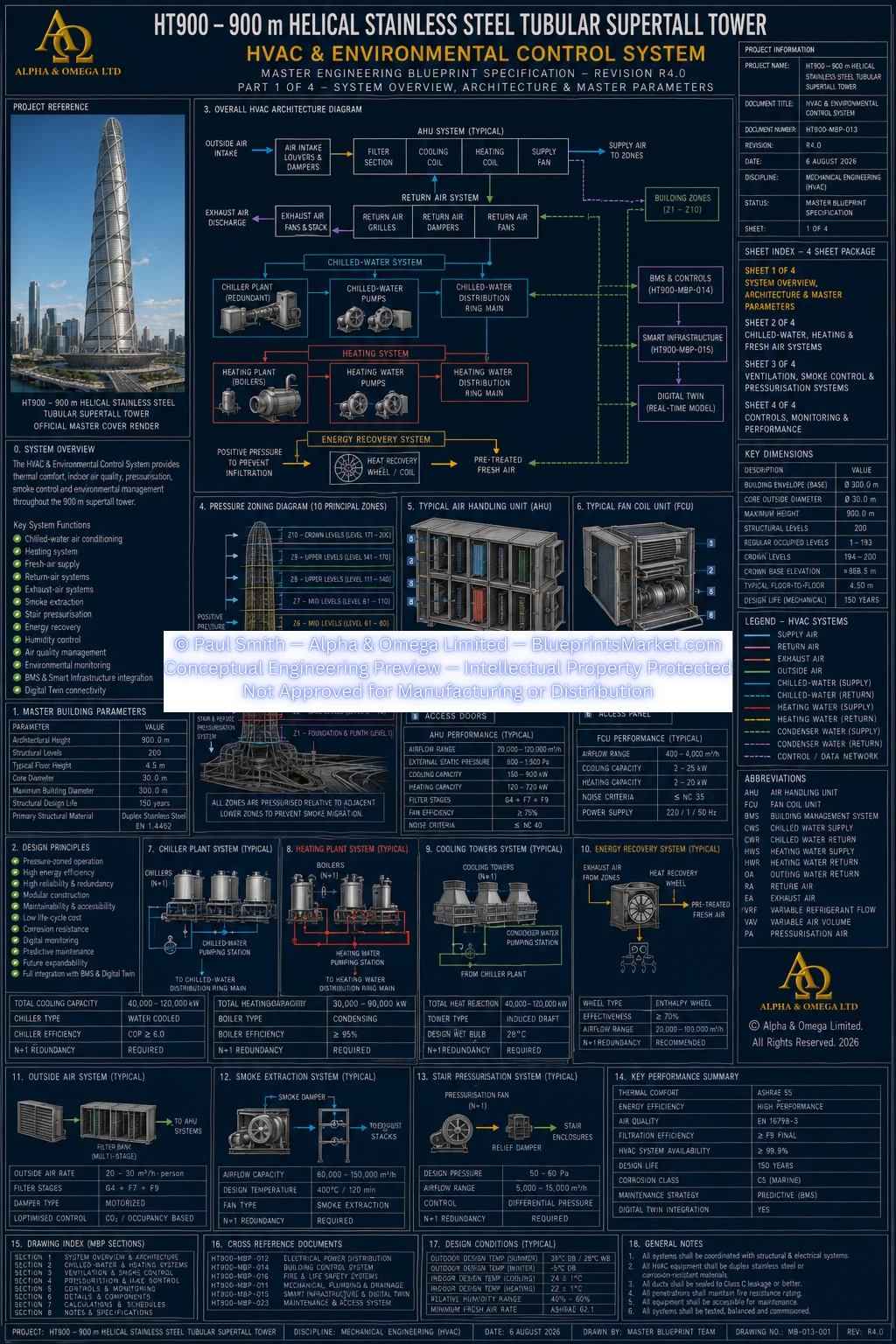
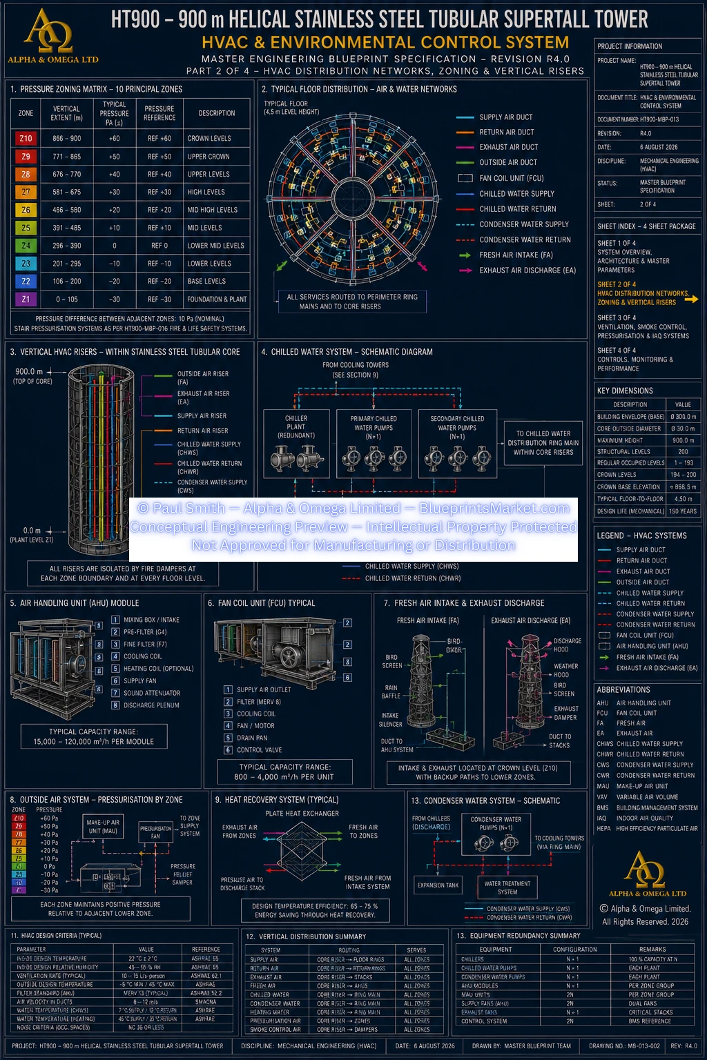
HT900-MBP-013 — HVAC & ENVIRONMENTAL CONTROL SYSTEM
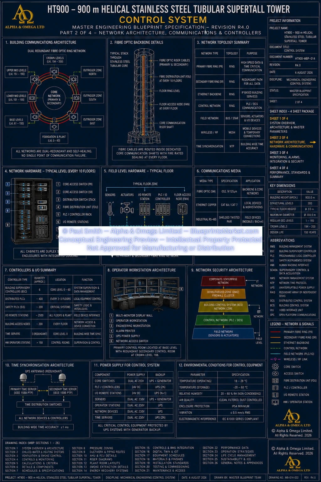
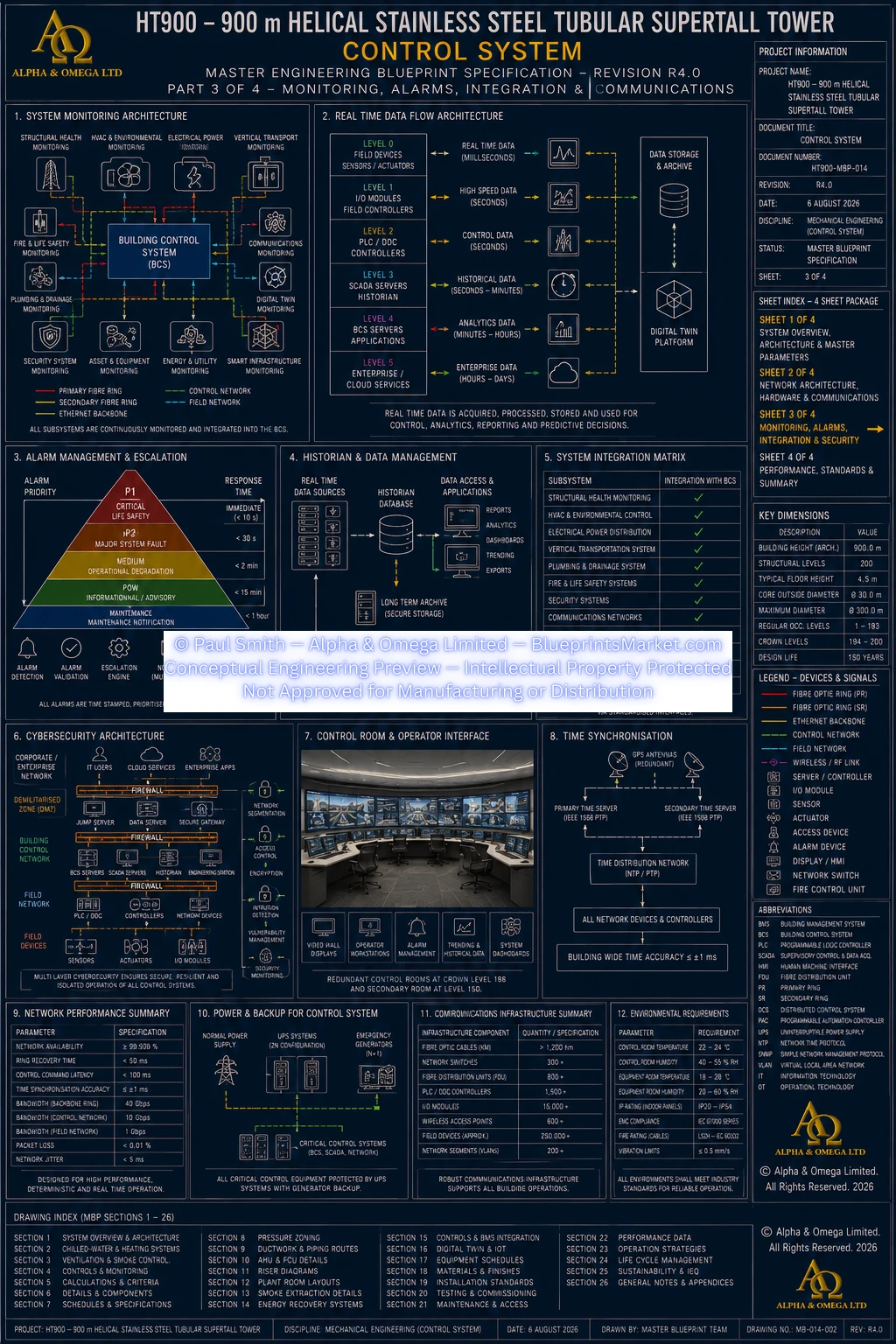
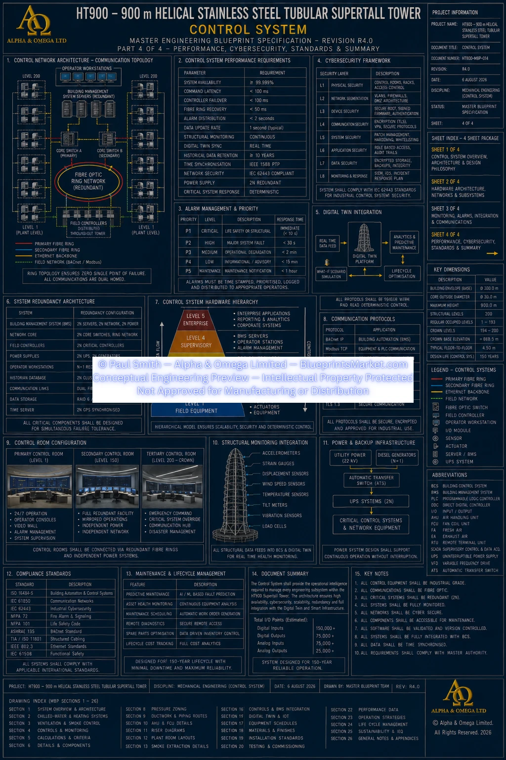
HT900-MBP-014 — CONTROL SYSTEM
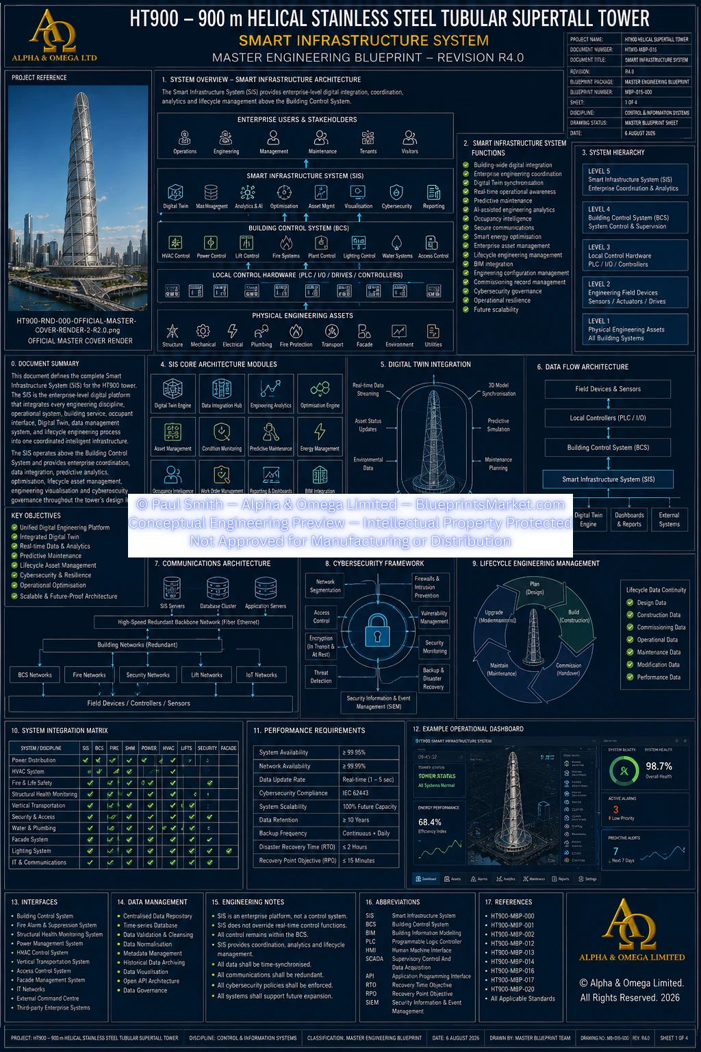
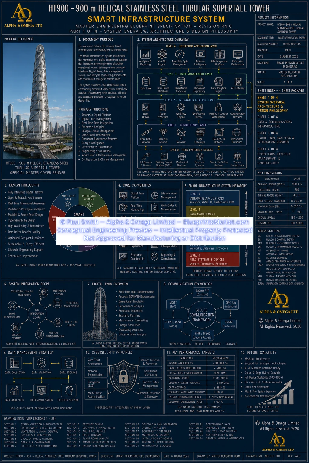
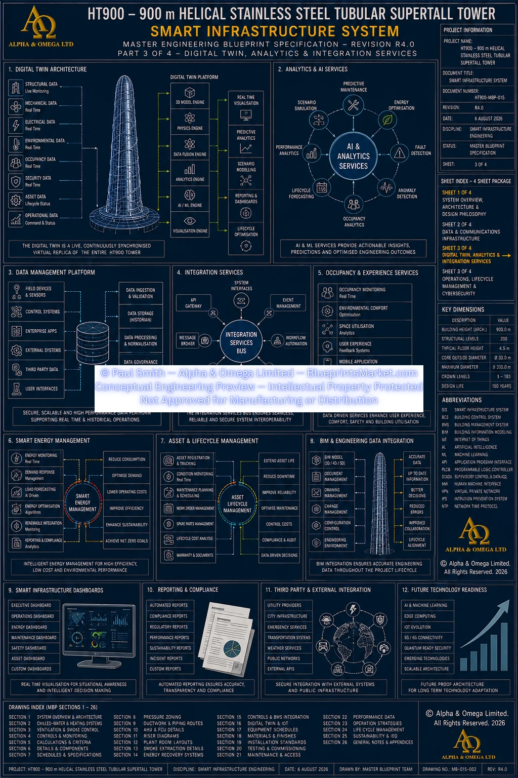
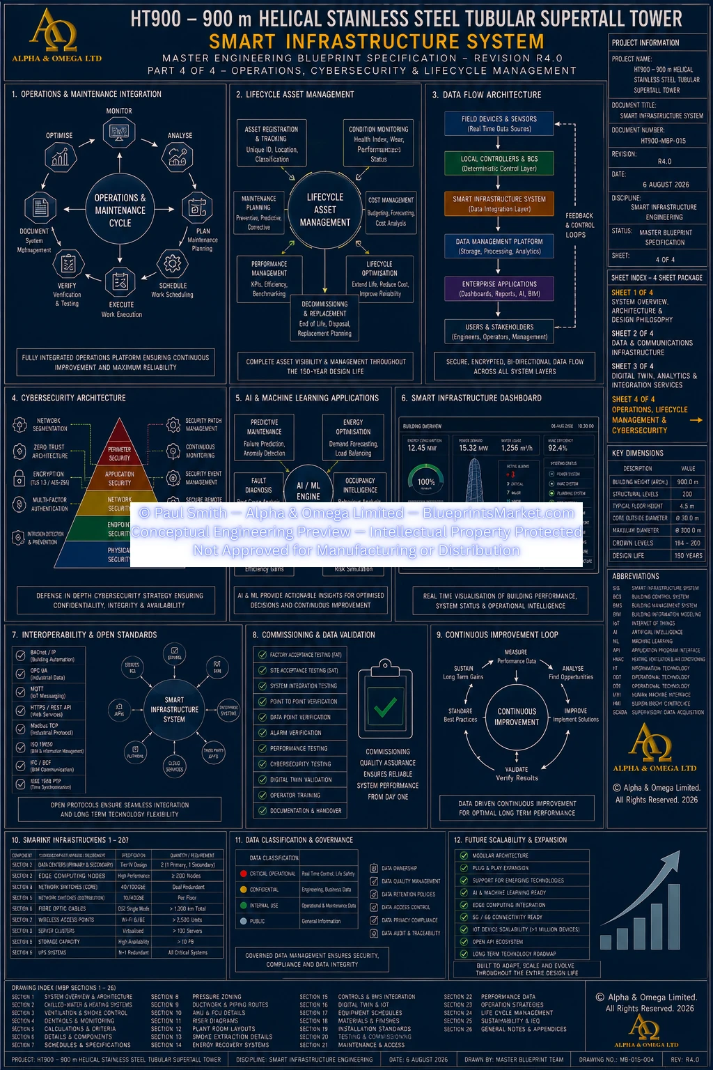
HT900-MBP-015 — SMART INFRASTRUCTURE SYSTEM

Copyright — Alpha & Omega Limited
All blueprint files, CAD parameters, architectural concepts, engineering specifications, and written content are the exclusive intellectual property of Alpha & Omega Limited. No part of the Stainless‑Steel Skyscraper Blueprint Package may be reproduced, distributed, or adapted without written consent.
Licensing, Copyright & Patent Restrictions
This engineering system and all associated blueprint materials, CAD files, diagrams, schematics, dimensional tables, and technical narratives are licensed, not sold, and remain the exclusive intellectual property of Alpha & Omega Limited.
This product is not eligible for patenting by any purchaser, user, organization, or third party. Patent filings, provisional patents, utility models, derivative patents, reverse‑engineering for patent purposes, and intellectual property claims are strictly prohibited.
Redistribution, resale, sublicensing, public posting, dataset inclusion, or any form of unauthorized duplication of blueprint materials, CAD files, diagrams, or engineering concepts is strictly prohibited. No license tier grants ownership, patent rights, or rights to file for intellectual property protection.
All architectural & engineering systems are conceptual and require full professional engineering validation before any real‑world use, construction, prototyping, or structural implementation.
Full legal details are available in the Terms & Conditions .