
1.0 Exterior Cladding & Curtain Wall System Overview
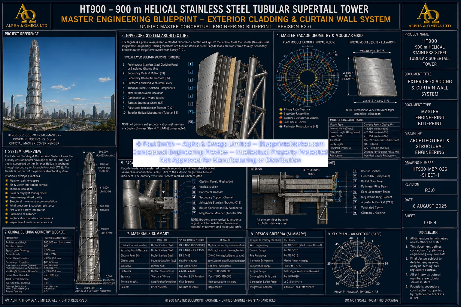
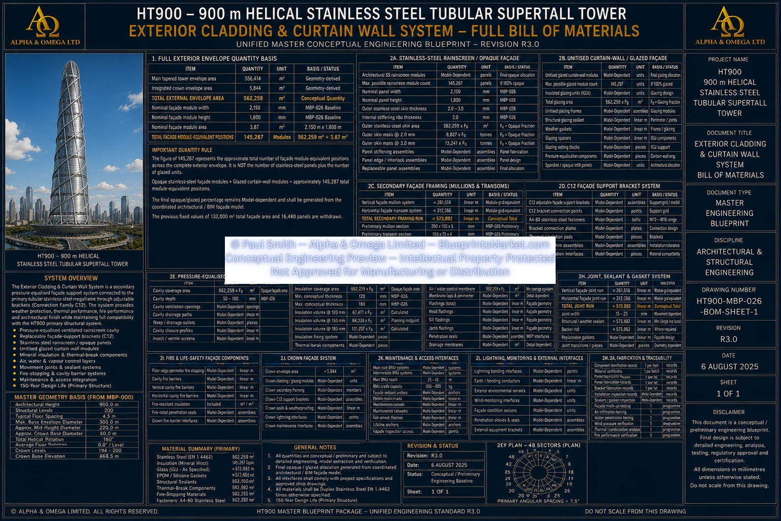
The HT900 Exterior Cladding & Curtain Wall System forms the primary environmental envelope of the 900 metre Helical Stainless-Steel Tubular Supertall Tower.
The façade combines architectural stainless-steel cladding, high-performance glazing, pressure-equalised weather protection, thermal control, structural-movement accommodation and replaceable support interfaces within the tower's continuously rotating helical geometry.
Primary Envelope Functions
- Weather-tight building enclosure
- Air-infiltration control
- Water-infiltration control
- Thermal insulation
- Condensation management
- Solar and daylight management
- Structural-movement accommodation
- Wind-pressure and suction resistance
- Fire and life-safety integration
- Long-term corrosion resistance
- Replaceable modular façade components
- Safe inspection and maintenance access
2.0 Locked Global Façade Geometry
The façade follows the current HT900 R3.0 master geometry and remains fully coordinated with the structural and aerodynamic systems of the tower.
| Architectural Height | 900.0 metres including crown |
|---|---|
| Structural Levels | 200 |
| Typical Structural Level Spacing | 4.5 metres |
| Maximum Base Envelope Diameter | 300.0 metres |
| Perimeter Column Centreline Diameter at Base | 270.0 metres |
| Approximate Mid-Height Envelope Diameter | 220 metres |
| Approximate Crown Base Diameter | 60 metres |
| Total Helical Rotation | 160° |
| Average Floor Rotation | 0.8° |
| Average Twist Rate | Approximately 0.178° per metre |
| Crown Levels | 194–200 |
| Approximate Crown Base Elevation | 868.5 metres |
The façade therefore changes progressively in diameter, orientation and projected geometry as it rises through the tower, requiring a modular envelope system capable of accommodating the controlled helical transformation.
3.0 Global Envelope Architecture
The HT900 envelope is conceived as a coordinated modular façade system integrated with the Exterior Helical Megaframe while remaining functionally separate from the primary structural load-resisting system.
Principal Envelope Systems
- Architectural stainless-steel cladding
- Unitised high-performance curtain-wall glazing
- Insulated glazing systems
- Pressure-equalised façade cavities
- Continuous air barriers
- Continuous water barriers
- Thermal insulation systems
- Thermal-break systems
- Movement joints
- Façade anchors and support brackets
- Sealants and gasket systems
- Fire-stopping interfaces
- Lightning-protection interfaces
- Building Maintenance Unit interfaces
4.0 Typical Envelope Layering
Depending on façade zone, the exterior envelope may combine stainless-steel rainscreen construction and glazed curtain-wall assemblies within one coordinated helical façade system.
Typical Exterior-to-Interior Functional Layers
- Architectural stainless-steel cladding or glazed outer envelope
- Secondary façade framing
- Pressure-equalised drainage cavity
- Thermal-break interfaces
- Fire-safe insulation
- Continuous air and water-control layers
- Secondary support structure
- Replaceable façade-support brackets
- Exterior Helical Megaframe interface
Detailed layer thicknesses and component build-ups are determined during detailed façade, thermal, fire and waterproofing engineering.
5.0 Architectural Stainless-Steel Cladding
Architectural stainless-steel cladding forms a major element of the visual identity and long-term durability strategy of the HT900.
The cladding is supported independently from the primary structural load path through engineered secondary framing and replaceable attachment systems.
Primary Design Objectives
- Long-term corrosion resistance
- High-quality architectural appearance
- Controlled wind-load transfer
- Controlled thermal movement
- Moisture drainage
- Pressure equalisation
- Replaceable modular panels
- Compatibility with glazed façade zones
- Compatibility with maintenance systems
Final stainless-steel grade, panel dimensions, skin thicknesses, rib geometry, panel weight and surface finish remain subject to project-specific façade engineering and architectural requirements.
6.0 Unitised Curtain Wall System
Glazed sections of the HT900 envelope use a high-performance unitised curtain-wall philosophy coordinated with the changing helical geometry of the tower.
Principal Curtain-Wall Components
- High-performance insulated glazing units
- Unitised façade frames
- Vertical mullions
- Horizontal transoms
- Thermal-break systems
- Pressure-equalised joints
- Structural sealants
- Weather sealants
- Gaskets
- Drainage channels
- Movement-accommodation joints
- Replaceable modular units
Final glass build-up, frame profiles, coatings, spacers, connections and thermal properties require detailed façade design.
7.0 Pressure-Equalised Rainscreen System
Opaque cladding zones use pressure-equalised and drained rainscreen principles to manage wind-driven rain, condensation and moisture within the façade.
Principal Functions
- Pressure equalisation
- Moisture drainage
- Wind-driven rain control
- Condensation reduction
- Façade drying
- Air-barrier protection
- Water-barrier protection
- Thermal insulation protection
Cavity depths, insulation thicknesses, backup layers and drainage dimensions are determined from project-specific environmental, fire and façade-performance requirements.
8.0 Façade Support & Attachment System
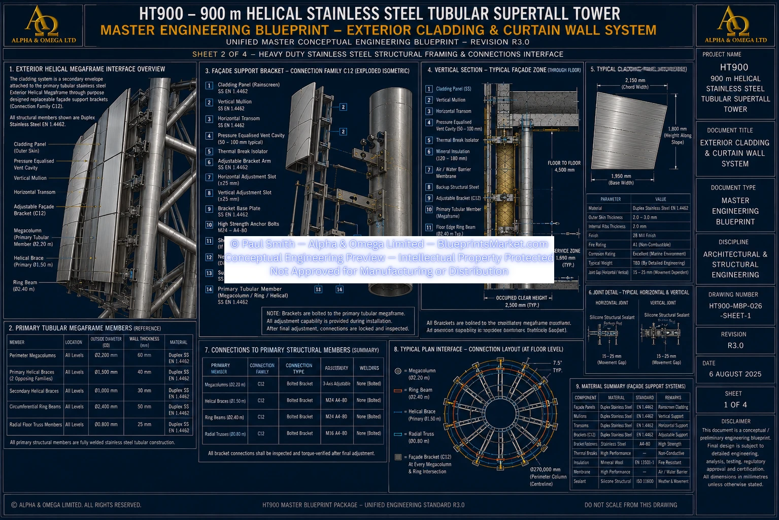
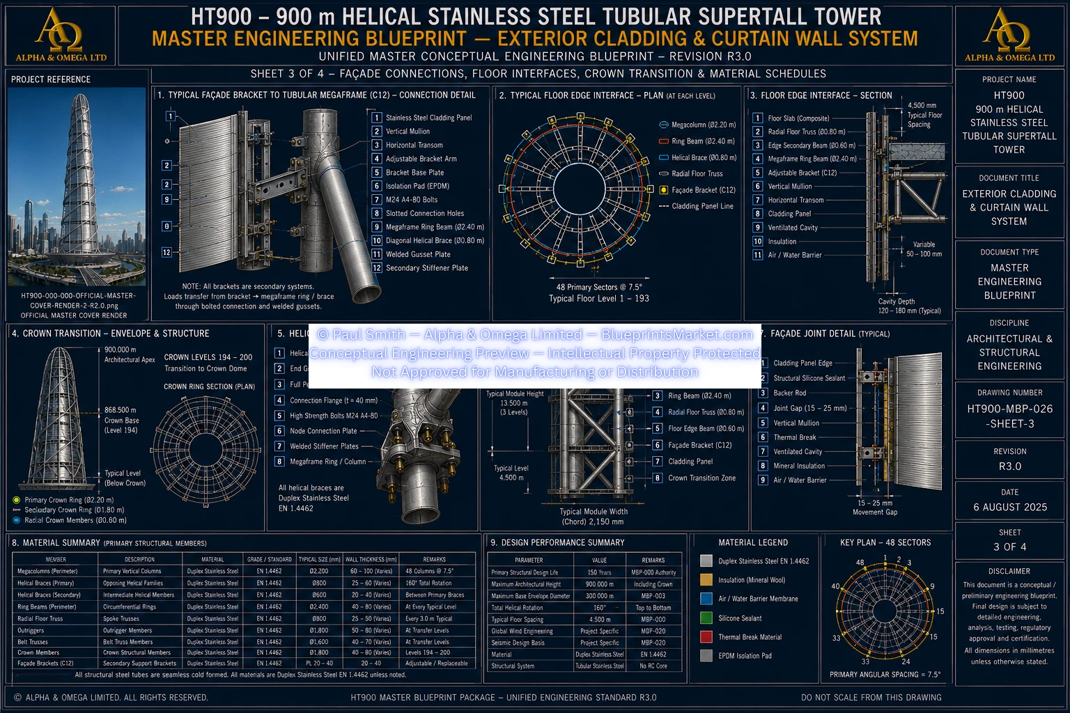
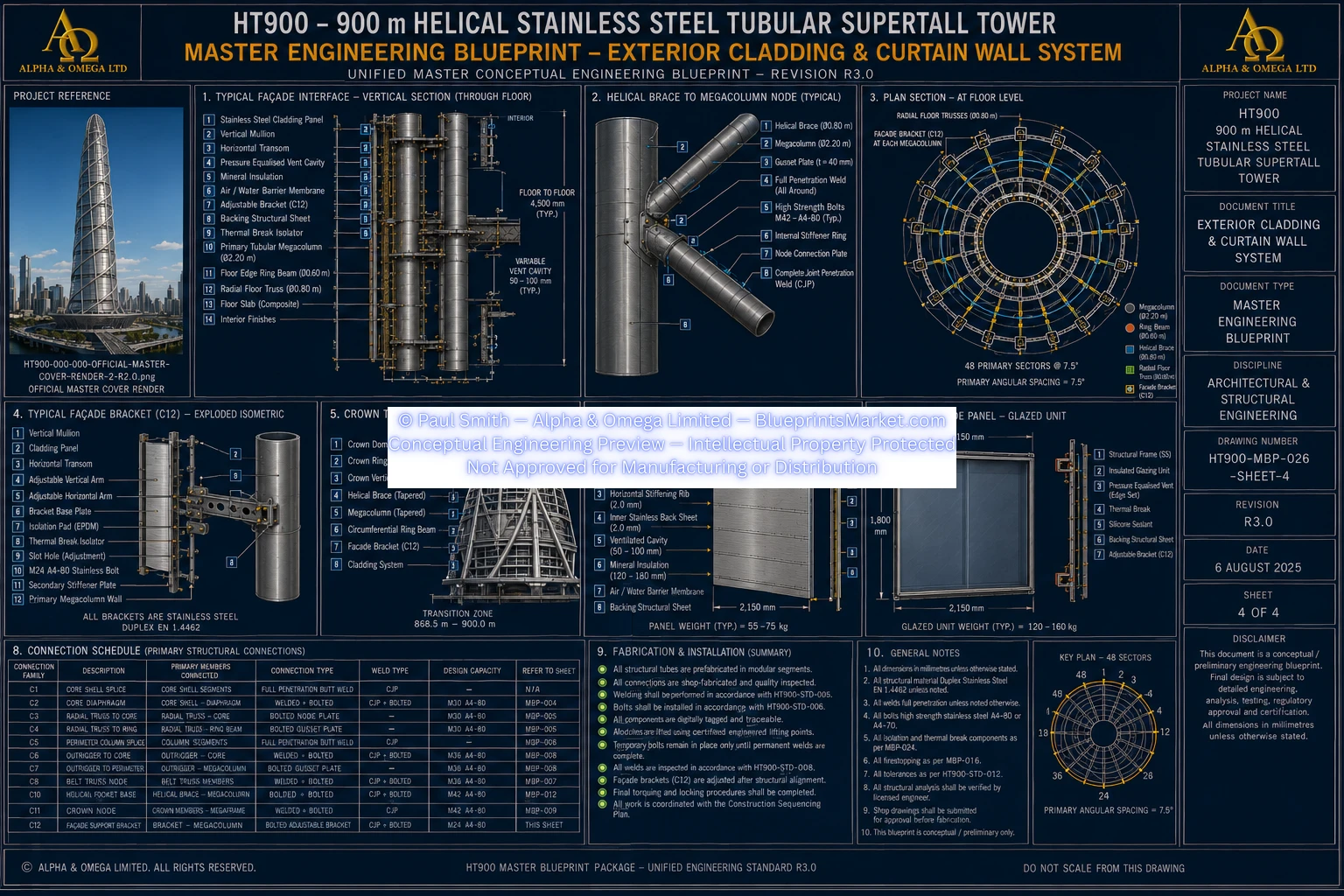
The HT900 Exterior Helical Megaframe provides the principal structural interface supporting the façade through secondary replaceable attachment brackets.
Principal Support Interfaces
- Exterior Helical Megaframe
- Perimeter structural columns
- Circumferential structural rings
- Floor-edge structural zones
- Crown structural interfaces
- Secondary façade-support framing
- Replaceable attachment brackets
Attachment-System Functions
- Transfer façade dead load
- Transfer local wind pressure and suction
- Accommodate construction tolerances
- Accommodate structural drift
- Accommodate thermal movement
- Accommodate seismic movement
- Permit inspection
- Permit local replacement
- Prevent incompatible metal contact
Detailed bracket dimensions, fastener sizes, slot dimensions and connection capacities remain within the detailed engineering design rather than being treated as universal façade values.
9.0 Façade Movement Joint System
Façade joints must accommodate the combined movement demands associated with a 900 metre supertall structure.
Movement Sources
- Thermal expansion and contraction
- Wind-induced structural drift
- Torsional structural response
- Seismic displacement
- Floor deflection
- Construction tolerances
- Long-term structural movement
Movement-Control Features
- Unitised façade modules
- Flexible joint systems
- Pressure-equalised joints
- Replaceable seals and gaskets
- Thermal-break interfaces
- Adjustable secondary support systems
Final joint widths and movement capacities require detailed façade-engineering calculations.
10.0 Aerodynamic Façade Integration
The façade follows the controlled HT900 helical and tapered form, allowing the external envelope to operate as part of the wider aerodynamic strategy of the tower.
Principal Aerodynamic Features
- 160° total helical rotation
- Progressive tower taper
- Continuously changing façade orientation
- Integrated exterior megaframe geometry
- Coordinated crown transition
- Controlled exterior discontinuities
The helical architectural form is intended to disrupt coherent aerodynamic excitation and coordinate external flow behaviour with the tower's overall wind-engineering strategy.
11.0 Façade Wind Engineering
Local façade wind pressure is wind-tunnel-derived and varies according to elevation, orientation, tower geometry, local edge conditions and surrounding terrain.
The current HT900 R3.0 baseline therefore does not use one universal wind-pressure or suction value for the complete façade.
Required Wind-Engineering Programme
- Boundary-layer wind-tunnel testing
- High-frequency pressure integration
- Aeroelastic model testing
- Cladding pressure mapping
- Full directional wind assessment
- Local edge and corner pressure analysis
- Crown wind assessment
- Building Maintenance Unit wind assessment
- Construction-stage wind assessment
- Pedestrian wind assessment
Final façade components are designed to the governing positive and negative pressures derived from this project-specific programme.
12.0 Thermal & Environmental Performance
Glazing, opaque cladding, insulation, thermal breaks and continuous environmental-control layers are coordinated to minimise energy loss and condensation while maintaining occupant comfort.
Environmental Objectives
- Thermal-bridge reduction
- Controlled solar gain
- Daylight optimisation
- Reduced unwanted heat transfer
- Condensation control
- Continuous insulation
- Air-tightness
- Water-tightness
- Energy-performance integration
Final insulation values, glass U-values, solar heat-gain coefficients and thermal-break performance remain subject to environmental modelling and façade engineering.
13.0 Fire & Life-Safety Integration
The exterior envelope is coordinated directly with the HT900 Fire & Life Safety System.
Principal Fire-Safety Requirements
- Fire-safe façade materials
- Non-combustible materials where required
- Perimeter fire stopping
- Cavity fire barriers
- Floor-edge fire separation
- Protected façade penetrations
- Smoke-spread control
- Compatible fire-resistant insulation systems
Final fire classifications and façade-fire performance require specialist project-specific fire engineering and regulatory approval.
14.0 Materials, Corrosion Resistance & Durability
The façade material strategy supports the wider HT900 philosophy of long-term durability, corrosion resistance, inspection accessibility and modular replacement.
Durability Principles
- Corrosion-resistant stainless-steel components
- Compatible structural fasteners
- Dissimilar-metal isolation
- Drainage and crevice control
- Replaceable sealants
- Replaceable gaskets
- Replaceable glazing
- Replaceable cladding modules
- Accessible support connections
- Routine façade inspection
- Long-term maintenance planning
Product-specific mechanical properties are established from certified material specifications rather than assuming one universal strength value across every façade component.
15.0 Crown & Upper Façade Transition
The primary tower façade transitions progressively into the integrated Crown Dome over Levels 194–200.
| Crown Levels | 194–200 |
|---|---|
| Approximate Crown Base Elevation | 868.5 metres |
| Architectural Apex | 900.0 metres |
Crown Envelope Interfaces
- Crown structural framing
- Architectural stainless-steel cladding
- Glazed façade zones where applicable
- Weatherproofing systems
- Lightning-protection interfaces
- Communications equipment interfaces
- Maintenance-access systems
- Building Maintenance Unit interfaces
16.0 Lightning Protection & External Equipment
The exterior envelope is integrated with the tower's lightning protection and external equipment infrastructure without compromising the air, water, thermal or fire performance of the façade.
Principal Interfaces
- Lightning conductors
- Structural bonding
- Environmental sensors
- Wind instrumentation
- Communications equipment
- Maintenance equipment
- Crown equipment
17.0 Façade Inspection & Maintenance
Long-term façade inspection and maintenance are incorporated into the HT900 Maintenance & Access philosophy.
Maintenance Provisions
- Building Maintenance Units
- Façade-access systems
- Crown access systems
- Maintenance platforms
- Inspection routes
- Accessible attachment brackets
- Replaceable façade panels
- Replaceable glazing units
- Replaceable seals and gaskets
- Safe cleaning provisions
18.0 Modular Fabrication Philosophy
Façade components are intended for controlled off-site fabrication before progressive installation onto structurally released areas of the tower.
Fabrication Objectives
- Controlled dimensional accuracy
- Repeatable modular manufacture
- Controlled surface finishes
- Material traceability
- Component identification
- Factory quality control
- Protected transport
- Efficient site installation
- Future replaceability
Detailed fabrication tolerances vary according to component type, manufacturing process and façade-engineering requirements and are not governed by one universal ±1 mm value.
19.0 Façade Installation Sequence
Façade installation progresses after the relevant structural zones have achieved required survey and structural acceptance.
Typical Installation Logic
- Verify primary structural geometry
- Survey façade-support interfaces
- Install secondary support brackets
- Install environmental-control interfaces
- Install insulation and fire barriers
- Install curtain-wall units and cladding modules
- Complete movement joints
- Complete weather seals
- Verify drainage paths
- Inspect support connections
- Perform required façade testing
- Record installation and inspection information
20.0 Façade Testing & Verification
HT900 façade performance must be demonstrated through project-specific engineering analysis and physical testing rather than assumed through generic pass/fail statements.
Verification Programme
- Wind-pressure resistance testing
- Wind-suction resistance testing
- Cladding-pressure mapping
- Structural deflection verification
- Air-infiltration testing
- Static water-penetration testing
- Dynamic water testing where required
- Movement testing
- Thermal-performance assessment
- Condensation assessment
- Fire-performance verification
- Material-compatibility testing
- Corrosion assessment
- Full-scale façade mock-up testing where required
21.0 Design-Life & Replacement Philosophy
The HT900 primary structural system has a 150-year structural design-life objective.
Façade systems, however, consist of components with different inspection, maintenance and replacement intervals and therefore are not all assigned one universal 150-year service life.
Lifecycle Strategy
- Long-life stainless-steel support infrastructure
- Replaceable cladding panels
- Replaceable curtain-wall units
- Replaceable glazing
- Replaceable sealants
- Replaceable gaskets
- Inspectable façade brackets
- Routine condition inspection
- Periodic performance testing
- Long-term façade maintenance records
22.0 System Integration
The Exterior Cladding & Curtain Wall System is coordinated directly with the wider HT900 engineering architecture.
- Global Geometry
- Exterior Helical Megaframe
- Helical Structural System
- Radial Floor Structural System
- Crown Dome Structure
- Aerodynamic & Wind Engineering
- Fire & Life Safety System
- HVAC & Environmental Control System
- Electrical & Lightning Protection Systems
- Smart Infrastructure
- Structural Health Monitoring
- Construction Sequencing
- Maintenance & Access System
23.0 Façade Engineering Logic Summary
- The façade follows the current 900 metre, 300 metre-base-envelope, 160° helical geometry.
- Architectural stainless-steel cladding and unitised curtain-wall glazing form the primary exterior envelope systems.
- The façade is connected to the Exterior Helical Megaframe through secondary replaceable support interfaces.
- Pressure-equalised drainage, continuous air and water barriers, thermal insulation and thermal breaks provide the primary environmental-control strategy.
- Façade joints accommodate thermal movement, wind drift, torsional response and seismic displacement.
- Local façade pressure is wind-tunnel-derived and mapped over the complete tower envelope.
- Fire barriers and perimeter fire stopping integrate the envelope with the HT900 Fire & Life Safety System.
- Permanent maintenance systems and replaceable modular components support long-term inspection and lifecycle management.
24.0 Professional Engineering Notice
The HT900 Exterior Cladding & Curtain Wall System forms part of the HT900 R3.0 conceptual Master Blueprint Package.
This public page summarises the principal façade architecture, current global geometry, envelope systems, structural interfaces, weather-protection philosophy, aerodynamic integration, movement-accommodation strategy, maintenance philosophy and performance-verification requirements.
Detailed panel dimensions, panel thicknesses, mullion and transom sections, glazing build-ups, bracket geometry, exact fastener schedules, cavity dimensions, insulation thicknesses, joint widths, sealant specifications, local wind pressures, fabrication tolerances and component quantities are intentionally not presented as fixed public HT900 specifications.
These details remain within the applicable technical documentation where established or require subsequent project-specific façade, structural, thermal, fire, waterproofing, wind and materials engineering.
Any real-world implementation requires complete site-specific façade engineering, structural verification, wind-tunnel testing, thermal modelling, fire engineering, full-scale testing where required, approved construction documentation, regulatory approval and certification by appropriately qualified and licensed professionals.
HT900-MBP-026 — Exterior Cladding & Curtain Wall System
Copyright — Alpha & Omega Limited
All blueprint files, CAD parameters, architectural concepts, engineering specifications, and written content are the exclusive intellectual property of Alpha & Omega Limited. No part of the Stainless‑Steel Skyscraper Blueprint Package may be reproduced, distributed, or adapted without written consent.
Licensing, Copyright & Patent Restrictions
This engineering system and all associated blueprint materials, CAD files, diagrams, schematics, dimensional tables, and technical narratives are licensed, not sold, and remain the exclusive intellectual property of Alpha & Omega Limited.
This product is not eligible for patenting by any purchaser, user, organization, or third party. Patent filings, provisional patents, utility models, derivative patents, reverse‑engineering for patent purposes, and intellectual property claims are strictly prohibited.
Redistribution, resale, sublicensing, public posting, dataset inclusion, or any form of unauthorized duplication of blueprint materials, CAD files, diagrams, or engineering concepts is strictly prohibited. No license tier grants ownership, patent rights, or rights to file for intellectual property protection.
All architectural & engineering systems are conceptual and require full professional engineering validation before any real‑world use, construction, prototyping, or structural implementation.
Full legal details are available in the Terms & Conditions .