
1.0 System Overview
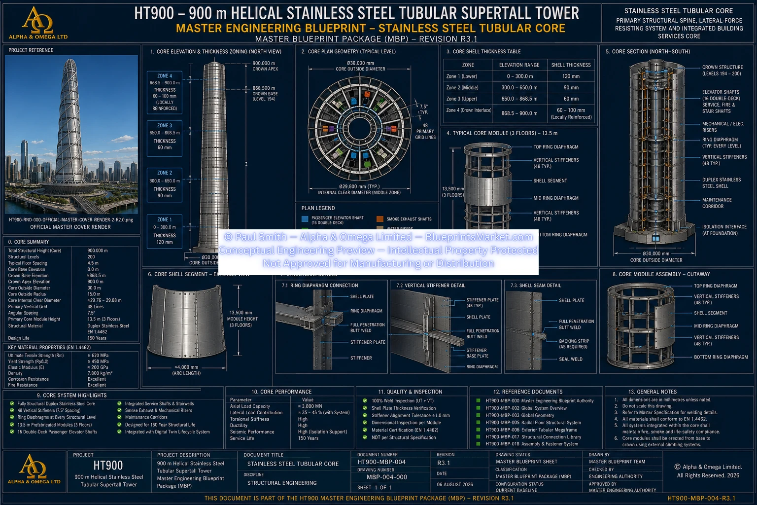
The HT900 Stainless Steel Tubular Core forms the principal internal structural spine of the 900 metre Helical Stainless-Steel Tubular Supertall Tower.
Unlike conventional supertall towers that commonly rely on a reinforced-concrete core, the HT900 concept uses a continuous circular Duplex Stainless Steel tubular structural core integrated with the wider tower structural system.
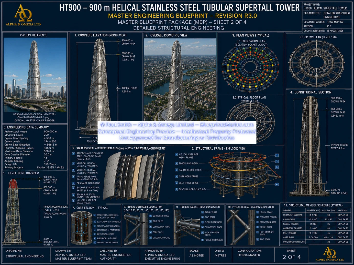
The core works together with the Exterior Helical Megaframe, Radial Floor Structural System, Concentric Support Rings, Helical Structural System, Outrigger & Belt-Truss System, Crown Dome Structure and isolation foundation to establish continuous structural load paths throughout the tower.
Primary Functional Role
- Principal vertical structural spine
- Continuous gravity-load transfer
- Lateral structural participation
- Torsional resistance
- Global structural continuity
- Radial floor-system support
- Outrigger and belt-truss structural interfaces
- Vertical transportation integration
- Protected building-services distribution
- Structural monitoring and inspection access
1.1 Master Core Geometry
The principal geometry of the Stainless Steel Tubular Core is coordinated directly with the locked HT900 global structural geometry.
| Structural Form | Continuous circular tubular structural shell |
|---|---|
| Outside Diameter | 30.0 metres |
| Core Radius | 15.0 metres |
| Overall Structural Height | 900.0 metres |
| Structural Levels | 200 |
| Typical Structural Level Spacing | 4.5 metres |
| Primary Structural Grid | 48 sectors |
| Primary Angular Spacing | 7.5° |
| Typical Core Erection Module | 13.5 metres — three structural levels |
| Primary Structural Material | EN 1.4462 Duplex Stainless Steel |
1.2 Core Design Philosophy
The Stainless Steel Tubular Core is designed around a continuous structural-shell philosophy extending from the foundation interface through the complete tower height to the Crown Dome transition.
Core Engineering Principles
- Continuous structural load path
- Fully structural stainless-steel core
- No reinforced-concrete structural core
- Precision modular construction
- Shared structural loading with the exterior megaframe
- Structural redundancy
- Integrated vertical building services
- Long-term corrosion resistance
- Permanent structural inspection accessibility
- Lifecycle structural monitoring
The HT900 structural philosophy deliberately distributes building loads across multiple structural systems rather than requiring the central core to resist every building action independently.
1.3 Variable Structural Shell Strategy
The tubular core uses a variable shell-thickness strategy in which structural capacity is progressively coordinated with changing tower loads and stiffness requirements over the height of the building.
Primary Structural Zones
- Lower structural core zone
- Middle structural core zone
- Upper structural core zone
- Locally reinforced Crown Dome transition zone
Additional local reinforcement is incorporated where required at high-demand structural interfaces such as major outrigger zones, heavy transfer regions, large structural openings and the crown transition.
Detailed shell thicknesses, local reinforcement geometry and fabrication dimensions remain governed by the HT900 technical documentation and subsequent detailed structural engineering.
1.4 Duplex Stainless Steel Material System
The principal structural components of the core are based on EN 1.4462 Duplex Stainless Steel.
Primary Applications
- Structural tubular shell
- Internal ring diaphragms
- Vertical stiffeners
- Internal structural framing
- Core structural interface nodes
- Outrigger reinforcement zones
- Crown transition structure
- Structural splice assemblies
Material Characteristics
| Elastic Modulus | Approximately 200 GPa |
|---|---|
| Shear Modulus | Approximately 77 GPa |
| Density | Approximately 7,850 kg/m³ |
| Poisson Ratio | Approximately 0.30 |
Final yield strength, tensile strength and other product-specific mechanical properties are determined from certified material specifications for the selected product form, thickness and governing engineering standard rather than being treated as one universal value.
1.5 Corrosion Resistance & Durability
Duplex Stainless Steel provides the HT900 core with a high level of atmospheric and chloride corrosion resistance while supporting the tower's long-term structural durability philosophy.
Durability Strategy
- Duplex Stainless Steel primary construction
- Controlled fabrication procedures
- Weld cleaning
- Pickling and passivation
- Carbon-steel contamination prevention
- Surface-condition inspection
- Permanent inspection access
- Structural Health Monitoring
- Predictive maintenance
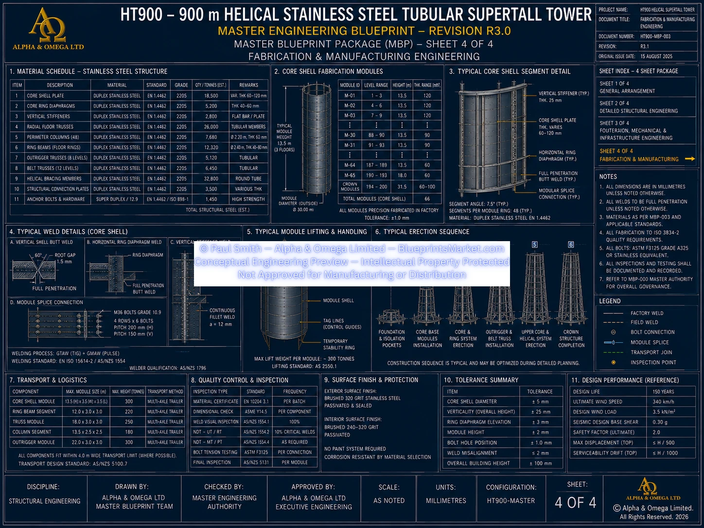
1.6 Modular Core Construction System
The HT900 Stainless Steel Tubular Core is not based on a conventional reinforced-concrete slipformed construction method.
Instead, the core is assembled from precision-manufactured stainless-steel shell modules produced under controlled fabrication conditions and progressively erected through the tower.
Typical Modular Configuration
| Typical Module Height | 13.5 metres |
|---|---|
| Structural Levels per Module Cycle | 3 |
Module Architecture
- Curved Duplex Stainless Steel shell panels
- Vertical stiffener segments
- Ring-diaphragm interfaces
- Structural splice preparations
- Temporary erection interfaces
- Survey-control provisions
- Service penetration provisions
- Core-to-floor structural nodes
Modular Construction Benefits
- Controlled dimensional accuracy
- Factory-managed welding quality
- Improved quality assurance
- Repeatable fabrication
- Reduced uncontrolled site fabrication
- Improved inspection access
- Coordinated structural continuity
1.7 Integrated Internal Core Architecture
The Stainless Steel Tubular Core provides a protected central structural volume for the tower's principal vertical transportation, emergency circulation, building services, communications and monitoring systems.
The internal arrangement is organised around the tower centreline to minimise eccentric structural loading and coordinate vertical infrastructure with the primary structure.
Principal Internal Functional Zones
- Vertical transportation
- Emergency egress
- Mechanical services
- Electrical distribution
- Communications infrastructure
- Structural monitoring
- Inspection and maintenance access
Detailed shaft quantities, service layouts, equipment arrangements and internal dimensions remain within the applicable HT900 subsystem documentation and subsequent project-specific design.
1.8 Ring Diaphragm System
Continuous internal structural ring diaphragms are incorporated at each structural floor level and form an important part of the tubular-shell stability system.
Vertical Spacing
| Ring Diaphragm Location | Every structural floor |
|---|---|
| Typical Vertical Spacing | 4.5 metres |
Primary Functions
- Reduce shell ovalisation
- Increase circumferential stiffness
- Improve torsional rigidity
- Transfer radial floor loads
- Support vertical stiffeners
- Distribute local structural stresses
- Improve shell buckling resistance
- Provide structural redundancy
1.9 Vertical Stiffener System
Continuous vertical stiffener lines provide additional shell stability, axial capacity and structural interface support throughout the tower height.
| Vertical Stiffener Lines | 48 |
|---|---|
| Angular Spacing | 7.5° |
The 48-line stiffener arrangement is coordinated with the tower's 48-sector structural grid, radial floor sectors and principal perimeter structural geometry.
Primary Functions
- Increase axial structural capacity
- Improve shell buckling resistance
- Provide local shell reinforcement
- Support ring diaphragms
- Support floor-interface nodes
- Reinforce outrigger interface regions
- Continue structural support into the Crown Dome transition
1.10 Core-to-Floor Structural Interface
Every structural floor interfaces with the tubular core through a coordinated system of radial structural connections and internal ring diaphragms.
Primary Interface Components
- Radial structural connection nodes
- Ring-diaphragm interfaces
- Primary floor-truss supports
- Structural monitoring provisions
Conceptual Load Transfer
Floor loads are distributed through the Radial Floor Structural System and Concentric Support Rings into both the Stainless Steel Tubular Core and the wider exterior structural system.
The HT900 therefore uses a shared structural load-path philosophy rather than directing all floor loads exclusively into the core.
1.11 Outrigger & Belt-Truss Interface
Major outrigger transfer zones couple the Stainless Steel Tubular Core with the perimeter structural system and form important stiffness-transfer regions within the tower.
Outrigger Interface Strategy
- Major outrigger zones coordinated at approximately 20 structural-level intervals
- Locally reinforced core shell regions
- Heavy structural reinforcement rings
- Internal diaphragm reinforcement
- Large structural node assemblies
- Permanent inspection access
Detailed outrigger-node geometry and connection specifications remain within the applicable HT900 structural documentation.
1.12 Crown Dome Interface
At the upper tower, the tubular core transitions into the integrated Crown Dome Structure.
| Crown Transition Region | Approximately +868.5 m to +900.0 m |
|---|---|
| Crown Apex | 900.0 m |
Integrated Crown Interfaces
- Locally reinforced core shell
- Crown structural support ring
- Helical frame interface
- Tuned Mass Damping System support interface
- Mechanical support framing
- Maintenance and inspection access
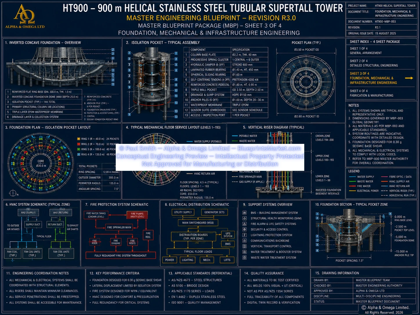
1.13 Foundation & Isolation Interface
The lower tubular core connects into the wider HT900 foundation and seismic-isolation architecture through a continuous structural interface.
Principal Interfaces
- Base structural ring
- Isolation support system
- Inverted Dome Foundation
- Seismic-isolation architecture
- Deep-foundation load-transfer system
This provides structural continuity from the tower superstructure through the isolation system and ultimately into the deep foundation and competent founding strata.
1.14 Global Structural Load-Path Philosophy
The Stainless Steel Tubular Core participates in gravity, wind, seismic and torsional load transfer as one component of the wider integrated HT900 structural system.
Gravity Load Path
Occupancy & equipment → floor assemblies → radial structural framing → concentric support rings → tubular core + exterior megaframe → isolation support system → deep foundation.
Wind Load Path
Façade → exterior structural system → helical structural system → floor and ring systems → outriggers → tubular core → isolation foundation → deep foundation.
Seismic Load Path
Ground motion → deep foundation → inverted-dome foundation → seismic-isolation system → tubular core and floor structure → exterior megaframe → complete superstructure.
1.15 Fabrication & Erection Philosophy
The tubular core is designed for precision off-site fabrication using modular stainless-steel construction techniques.
Factory Fabrication Principles
- Certified Duplex Stainless Steel structural plate
- Precision cutting and machining
- Controlled plate forming
- Factory trial assembly
- Qualified structural welding
- Dimensional verification
- Weld inspection
- Pickling and passivation
- Material traceability
Typical Erection Philosophy
- Complete foundation and seismic-isolation system
- Establish foundation structural interface
- Install first modular tubular core section
- Verify global survey position
- Install subsequent three-floor module
- Complete permanent structural continuity
- Integrate floor structural systems
- Integrate exterior structural systems
- Repeat modular erection cycle through tower height
- Complete Crown Dome transition
- Complete final structural survey and inspection
1.16 Inspection & Structural Health Monitoring
Inspection and monitoring are incorporated into the Stainless Steel Tubular Core as part of the HT900 long-term structural management philosophy.
Inspection Framework
- Material certification
- Dimensional inspection
- Weld inspection
- Non-Destructive Testing where required
- Surface-condition inspection
- Structural survey verification
- Long-term condition monitoring
Structural Monitoring Concepts
- Strain monitoring
- Acceleration monitoring
- Displacement monitoring
- Temperature monitoring
- Tilt monitoring
- Weld-condition monitoring
- Corrosion monitoring
- Structural vibration monitoring
Detailed sensor quantities, locations, monitoring logic and installation specifications remain within the applicable HT900 technical documentation and subsequent detailed project design.
1.17 Fire & Life-Safety Integration
The Stainless Steel Tubular Core provides the primary protected central structural volume for critical vertical transportation, emergency circulation and building-services systems.
Protected Core Functions
- Passenger vertical transportation
- Emergency and firefighter vertical transportation
- Protected emergency stairways
- Mechanical risers
- Electrical risers
- Fire-water infrastructure
- Communications systems
- Emergency communications
Final passive fire protection, smoke control, fire-rating requirements and life-safety configurations are established during detailed professional fire-engineering design and regulatory review.
1.18 Design-Life & Maintenance Philosophy
The primary structural core has a target structural design life of 150 years.
Long-Term Structural Strategy
- Duplex Stainless Steel primary structure
- Corrosion-resistant detailing
- Permanent inspection access
- Structural Health Monitoring
- Condition-based maintenance
- Replaceable non-structural building systems
- Long-term structural survey and inspection
Elevators, building services, communications equipment, control systems and other non-primary structural components are intended to remain replaceable without requiring replacement of the main tubular structural shell.
1.19 System Integration
The Stainless Steel Tubular Core interfaces directly with every principal structural system within the HT900 concept.
- Radial Floor Structural System
- Concentric Support Rings
- Exterior Helical Mega-Frame
- Helical Structural System
- Outrigger & Belt-Truss System
- Crown Dome Structure
- Foundation & Seismic Isolation System
- Vertical Transportation System
- Mechanical, Plumbing & Drainage System
- Electrical Power Distribution System
- Fire & Life Safety System
- Control and Smart Infrastructure Systems
- Structural Health Monitoring
- Maintenance & Access Systems
1.20 Engineering Logic Summary
- The 30 metre circular Duplex Stainless Steel tubular core establishes the principal internal structural spine of the tower.
- The core works together with the Exterior Helical Megaframe, Radial Floor System, Helical Structural System and Outrigger & Belt-Truss System to create multiple coordinated load paths.
- Ring diaphragms at each structural level improve circumferential stiffness, torsional response and shell stability.
- 48 continuous vertical stiffener lines coordinate the core structure with the global 48-sector structural grid.
- 13.5 metre three-floor modular construction supports controlled factory fabrication and repeatable erection.
- Integrated vertical transportation, building services and life-safety infrastructure use the protected central structural volume without replacing the stainless-steel structural shell.
- Permanent inspection access and Structural Health Monitoring support the tower's long-term structural lifecycle strategy.
1.21 Professional Engineering Notice
The HT900 Stainless Steel Tubular Core forms part of the HT900 conceptual Master Blueprint Package.
This public page presents the principal structural philosophy, locked global geometry, material system, major component families, structural interfaces, modular construction concept and lifecycle engineering strategy.
Detailed shell thickness schedules, internal shaft arrangements, connection geometry, weld geometry, fastener schedules, local reinforcement details, fabrication dimensions, structural calculations, inspection schedules and implementation-level engineering information remain within the applicable HT900 technical documentation or require subsequent project-specific professional engineering.
Any real-world fabrication or construction requires complete structural analysis, detailed connection engineering, fabrication drawings, shop drawings, erection drawings, fire engineering, building-services coordination, site-specific engineering verification, regulatory approval and certification by appropriately qualified and licensed engineering professionals.
HT900-MBP-004 — STAINLESS STEEL TUBULAR CORE
Copyright — Alpha & Omega Limited
All blueprint files, CAD parameters, architectural concepts, engineering specifications, and written content are the exclusive intellectual property of Alpha & Omega Limited. No part of the Stainless‑Steel Skyscraper Blueprint Package may be reproduced, distributed, or adapted without written consent.
Licensing, Copyright & Patent Restrictions
This engineering system and all associated blueprint materials, CAD files, diagrams, schematics, dimensional tables, and technical narratives are licensed, not sold, and remain the exclusive intellectual property of Alpha & Omega Limited.
This product is not eligible for patenting by any purchaser, user, organization, or third party. Patent filings, provisional patents, utility models, derivative patents, reverse‑engineering for patent purposes, and intellectual property claims are strictly prohibited.
Redistribution, resale, sublicensing, public posting, dataset inclusion, or any form of unauthorized duplication of blueprint materials, CAD files, diagrams, or engineering concepts is strictly prohibited. No license tier grants ownership, patent rights, or rights to file for intellectual property protection.
All architectural & engineering systems are conceptual and require full professional engineering validation before any real‑world use, construction, prototyping, or structural implementation.
Full legal details are available in the Terms & Conditions .