
1.0 System Overview
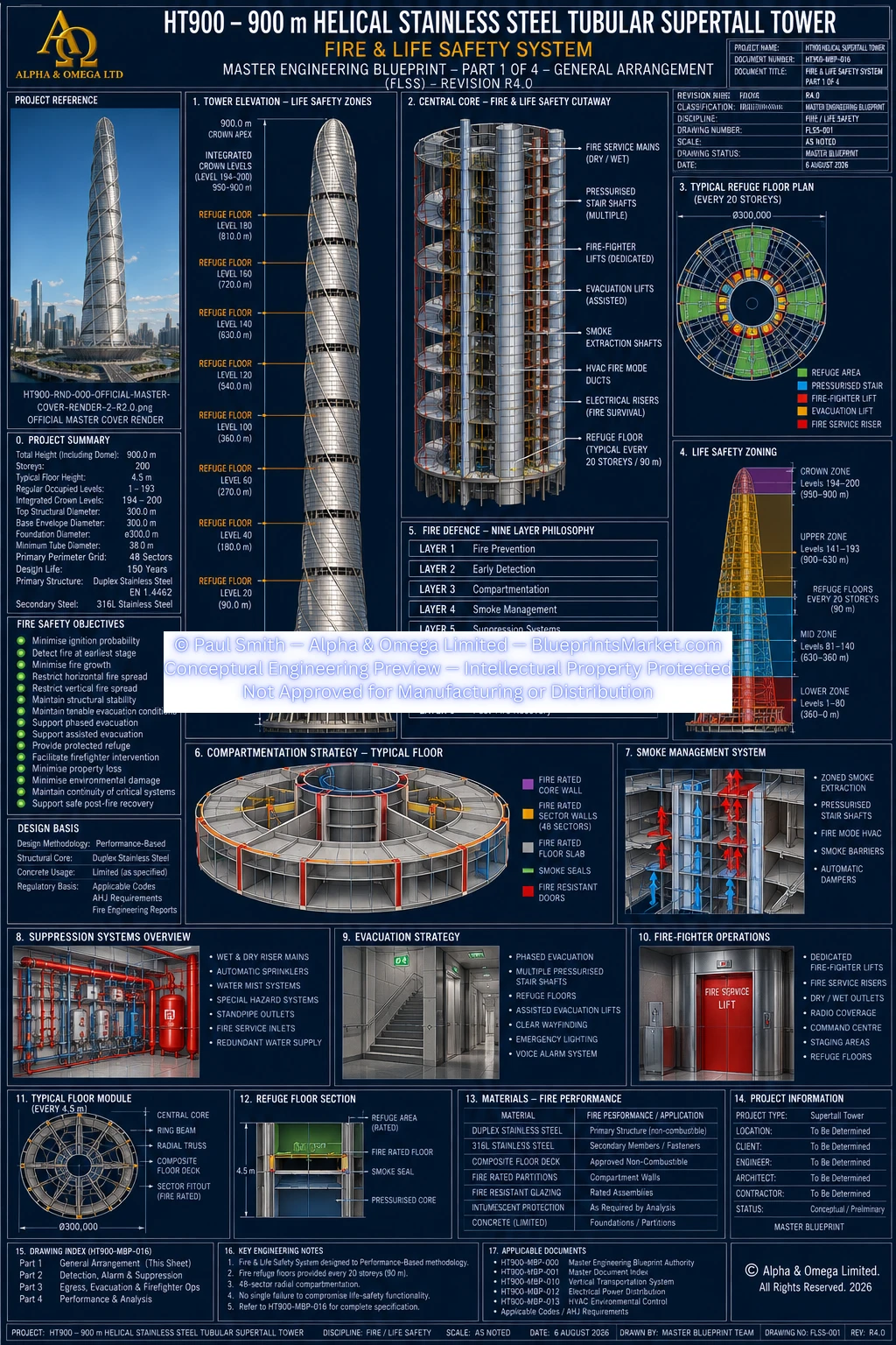
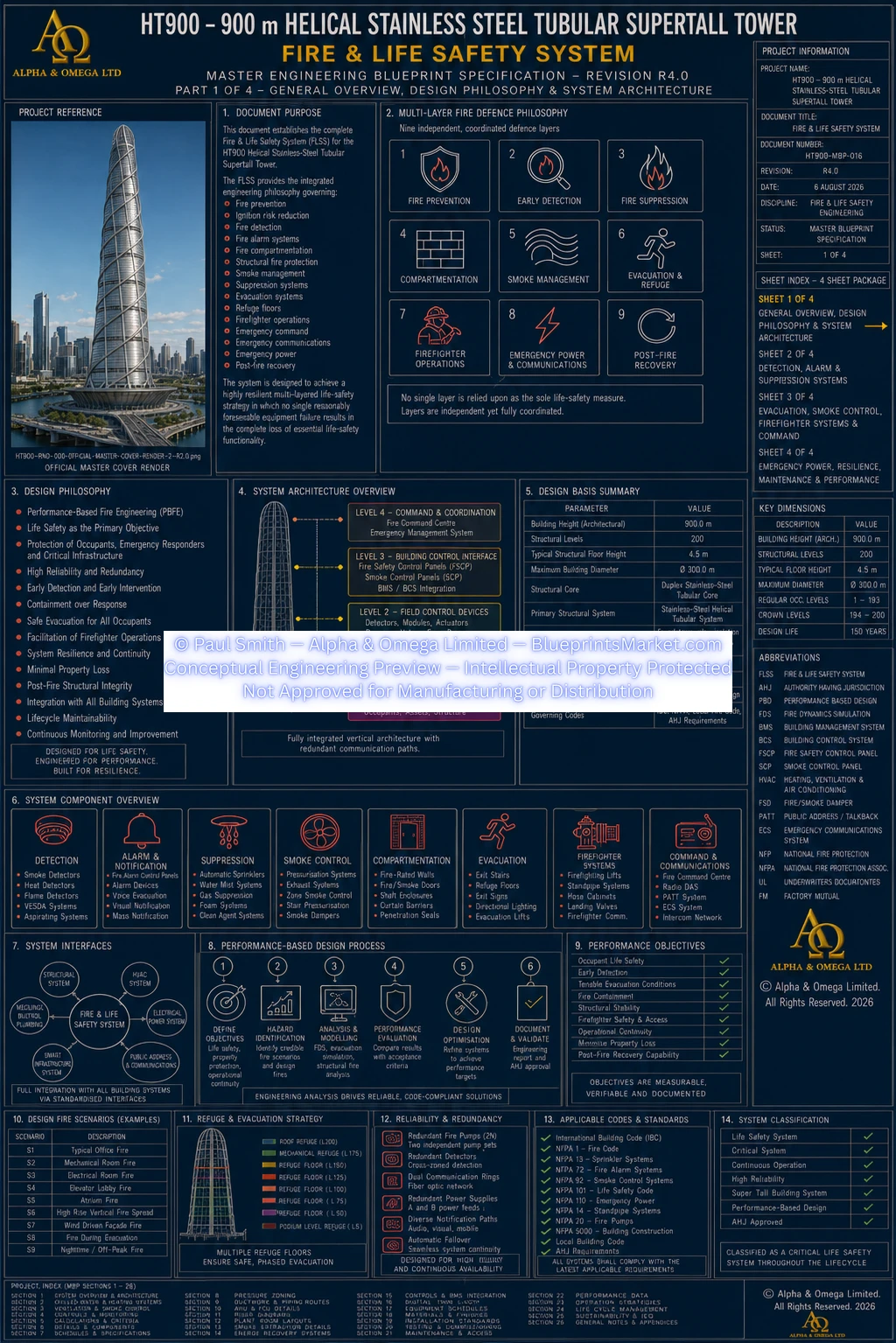
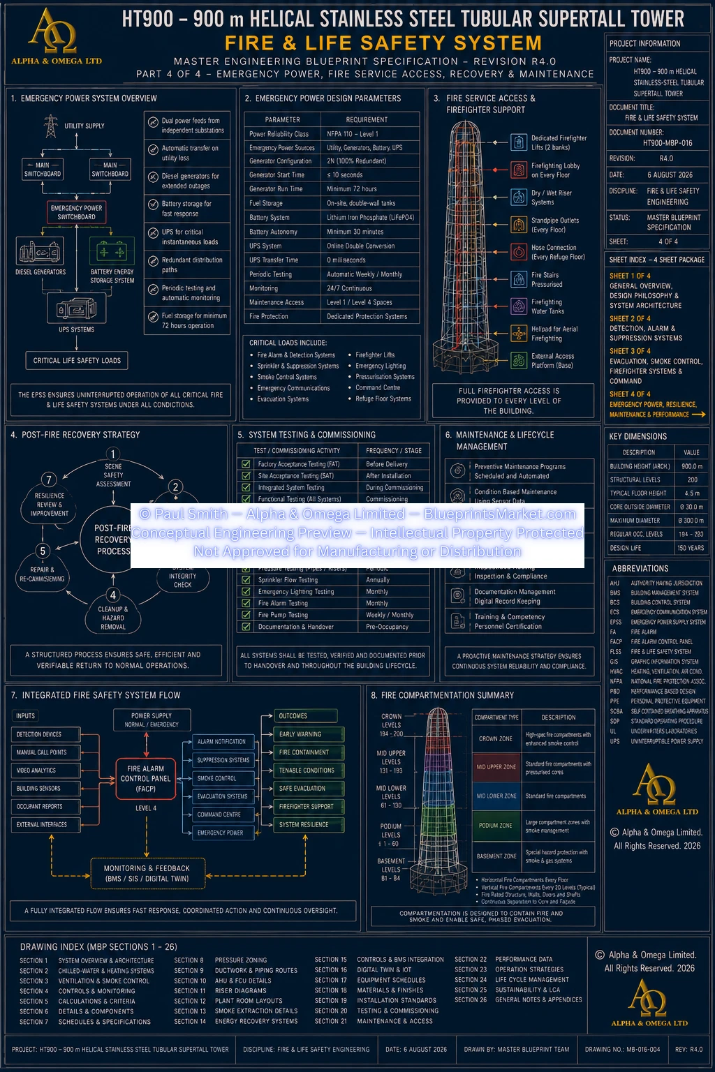
The HT900 Fire & Life Safety System provides the integrated life-safety framework for the 900-metre Helical Stainless-Steel Tubular Supertall Tower.
The system combines fire prevention, early detection, compartmentation, automatic suppression, smoke management, protected evacuation, firefighter operations, structural fire protection, emergency command, resilient communications, emergency power and post-incident recovery.
The design is based on a multi-layered resilience strategy so that essential life-safety functionality does not depend on one single system or component.
2.0 HT900 Fire Engineering Design Basis
| Architectural Height | 900 m |
|---|---|
| Structural Levels | 200 |
| Typical Structural Floor Height | 4.5 m |
| Maximum Building Envelope Diameter | 300 m |
| Primary Structural Core | Continuous Duplex Stainless-Steel Tubular Core |
| Primary Fire Engineering Approach | Performance-Based Fire Engineering |
The HT900 does not use a reinforced-concrete primary structural core. Fire engineering is coordinated directly with the tower's tubular stainless-steel structural system.
Concrete is used only in approved secondary or substructure applications such as foundations, floor toppings, fire partitions and other non-core elements where required.
3.0 Performance-Based Fire Engineering Philosophy
The HT900 Fire & Life Safety System is developed using a performance-based engineering methodology rather than relying only on fixed universal prescriptive assumptions.
Fire-safety decisions are coordinated using engineering assessment of:
- Fire dynamics
- Smoke movement
- Occupant movement
- Structural fire behaviour
- Suppression reliability
- Evacuation performance
- Emergency response
- Post-fire recovery
Final system capacities, ratings and performance criteria would be established through project-specific fire engineering, jurisdictional requirements and regulatory approval.
4.0 Nine-Layer Fire Defence Strategy
The HT900 life-safety architecture uses nine coordinated defence layers.
Layer 1 — Fire Prevention
- Ignition-risk reduction
- Electrical protection
- Equipment certification
- Operational controls
- Maintenance and monitoring
Layer 2 — Early Detection
- Addressable smoke detection
- Heat detection
- Multi-criteria detection
- Aspirating detection where appropriate
- Flame and gas detection in specialist areas
Layer 3 — Fire Compartmentation
- Fire-rated compartment boundaries
- Protected shafts
- Fire dampers
- Cavity barriers
- Penetration fire stopping
Layer 4 — Automatic Suppression
- Automatic sprinkler protection
- Special-hazard suppression where required
- Water mist where appropriate
- Clean-agent or other specialist systems where justified
Layer 5 — Smoke Management
- Smoke extraction
- Pressure control
- Protected evacuation routes
- Refuge-floor protection
- Controlled smoke purge
Layer 6 — Protected Evacuation
- Protected emergency stairs
- Refuge floors
- Emergency wayfinding
- Voice evacuation
- Assisted-evacuation provisions
Layer 7 — Firefighter Operations
- Protected firefighter access
- Dedicated firefighter elevators
- Firefighter communications
- Fire-water supplies
- Emergency command facilities
Layer 8 — Structural Fire Protection
- Protection of the stainless-steel structural core
- Protection of perimeter megaframe members
- Protection of outriggers and belt trusses
- Protection of floor trusses and critical transfer structures
- Project-specific structural fire analysis
Layer 9 — Recovery & Resilience
- Post-fire structural inspection
- Damage assessment
- System isolation
- Phased recommissioning
- Repair planning
- Digital incident records
5.0 Fire Compartmentation
The building is divided into coordinated fire compartments to restrict horizontal and vertical fire spread and support protected evacuation and firefighter operations.
Compartment design is coordinated with:
- Occupancy type
- Fire load
- Occupant density
- Smoke-control strategy
- Suppression systems
- Evacuation strategy
- Structural movement
- Fire-engineering assessment
No single universal compartment size is treated as the governing limit for the entire tower.
6.0 Structural Fire Protection
The HT900 primary load-bearing system is based on tubular Duplex Stainless Steel rather than a conventional reinforced-concrete structural core.
Structural fire engineering therefore evaluates the thermal response of the stainless-steel system, including:
- Temperature distribution
- Thermal expansion
- Connection behaviour
- Local and global stability
- Structural restraint effects
- Progressive-collapse resistance
- Post-fire residual capacity
Fire protection may include intumescent coatings, fire-resistant insulation, protected enclosures, thermal barriers and protected connection systems where required by engineering analysis.
Fire-protection requirements are not assumed to be identical for every structural member or every level of the tower.
7.0 Intelligent Fire Detection & Alarm
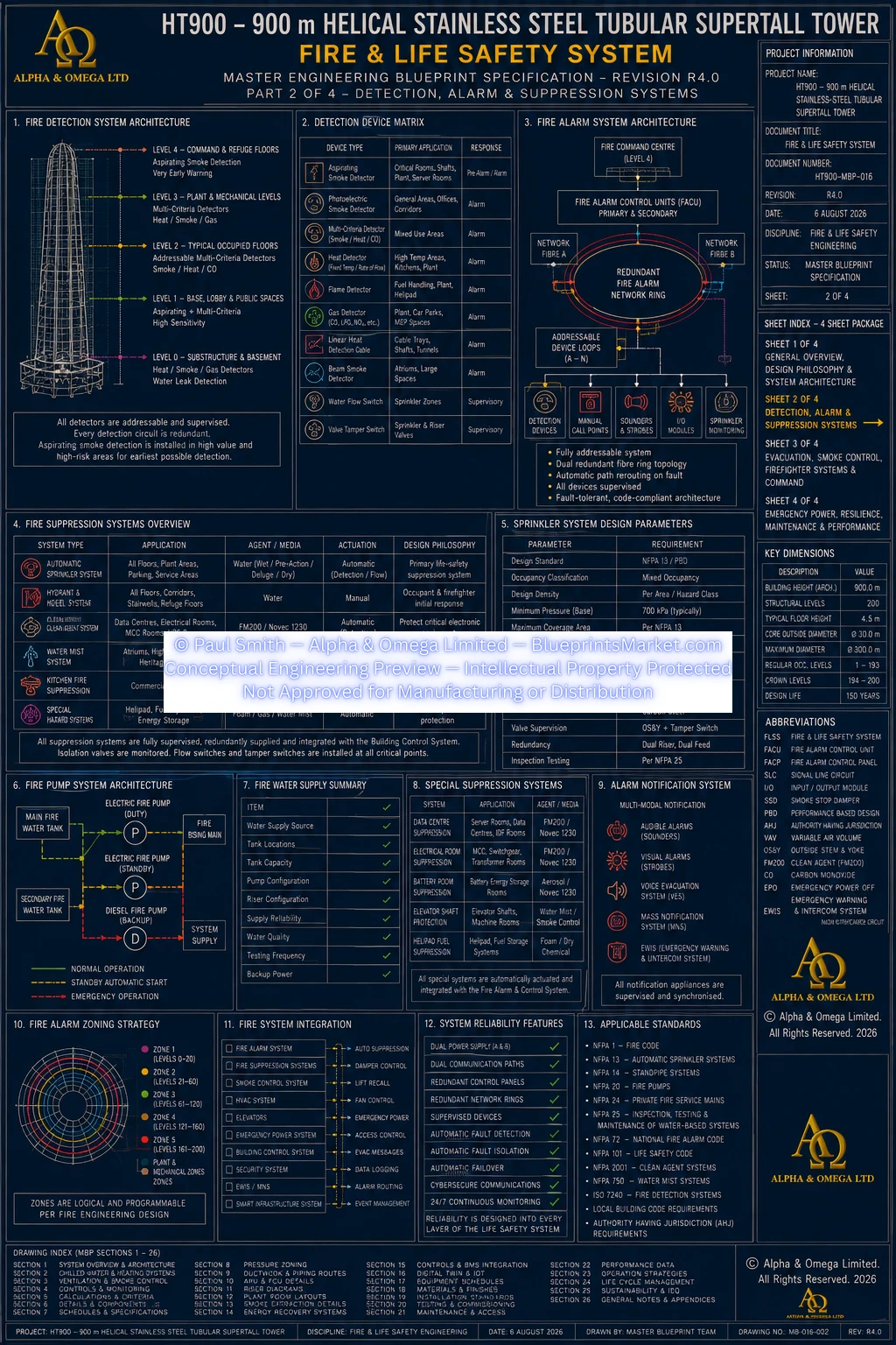
The tower incorporates a fully addressable intelligent fire-detection architecture designed for rapid identification, fault monitoring and coordinated emergency response.
Detection Technologies
- Photoelectric smoke detection
- Heat detection
- Multi-criteria detection
- Aspirating smoke detection
- Beam detection
- Flame detection
- Gas detection
- Linear heat detection where appropriate
Detector type and placement depend on occupancy, ceiling geometry, airflow, environmental conditions and the approved fire strategy.
The Fire Alarm System remains an independent certified life-safety system. General building automation and smart-building systems may monitor or display its status but do not replace the certified fire network.
8.0 Automatic Fire Suppression
Automatic suppression provides primary fire control throughout occupied areas of the tower.
Systems may include:
- Wet-pipe sprinkler systems
- Pre-action sprinkler systems
- Water-mist systems
- Clean-agent suppression
- Foam systems
- Wet-chemical suppression
- Dry-pipe systems where appropriate
Final suppression systems are selected according to occupancy, equipment hazards and hydraulic engineering requirements.
9.0 Pressure-Zoned Fire-Water Distribution
The HT900 does not rely upon one unrestricted full-height high-pressure water riser.
Instead, fire-water distribution is divided into controlled pressure zones throughout the height of the tower.
The system may incorporate:
- Ground-level water storage
- Intermediate storage
- Mechanical-level storage
- Refuge-level storage where required
- Emergency upper-level reserves
- Redundant pumping
- Pressure monitoring
- Isolation and surge-control systems
Storage capacity, pump duty and final pipe sizes are established through project-specific hydraulic calculations.
10.0 Smoke Management
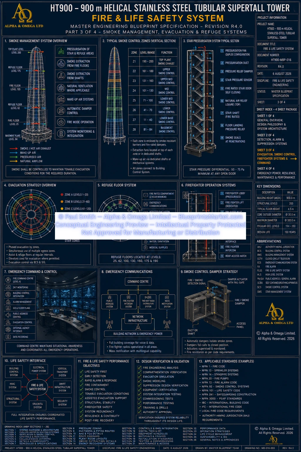
Smoke management is treated as an integrated performance-based system rather than simply a collection of extraction fans.
The strategy coordinates:
- Smoke-control zones
- Mechanical smoke extraction
- Controlled make-up air
- Pressurised stairs
- Protected lift lobbies
- Refuge-floor protection
- Fire dampers
- Smoke curtains and barriers where required
- Post-fire purge operation
Smoke-control performance is developed through fire modelling, pressure analysis and wind and stack-effect assessment.
11.0 Stack-Effect & Wind-Pressure Management
At 900 metres in height, the HT900 requires dedicated modelling of stack effect, reverse stack effect and external wind-pressure interaction.
These effects are evaluated in relation to:
- Protected stairs
- Lift shafts
- Smoke shafts
- Refuge floors
- Sky lobbies
- Mechanical levels
- Façade leakage
- Open-door conditions
- Emergency exhaust systems
Pressure management is coordinated to maintain tenable escape routes without creating excessive door-opening forces.
12.0 Protected Egress
The HT900 life-safety strategy incorporates four protected emergency stairs located within the tubular stainless-steel core.
Protected escape routes incorporate:
- Fire-rated enclosures
- Controlled positive-pressure protection
- Emergency lighting
- Emergency communications
- Smoke-resistant doors
- Protected access from occupied floors
- Connections to refuge floors
- Firefighter access
13.0 Refuge Floors
Dedicated refuge floors form a major part of the vertical life-safety strategy.
The conceptual baseline places refuge functions at approximately twenty-floor intervals, coordinated with principal service and structural levels where appropriate.
Refuge floors may provide:
- Protected occupant refuge
- Assisted-evacuation areas
- Wheelchair refuge spaces
- Firefighter staging
- Emergency medical response areas
- Emergency communications
- Independent smoke-control zones
- Emergency lighting and power
Final refuge-floor locations, capacity and configuration are subject to occupant-load analysis, evacuation modelling and licensed fire engineering.
14.0 Evacuation Strategy
The HT900 uses an engineered mixed-mode evacuation strategy appropriate to the scale and height of the tower.
The strategy may combine:
- Phased evacuation
- Partial relocation
- Refuge-assisted evacuation
- Stair evacuation
- Assisted evacuation
- Approved occupant evacuation elevators where applicable
- Firefighter-managed evacuation
Simultaneous evacuation of the entire building is not automatically assumed to be the normal operating strategy.
Evacuation analysis considers occupant loads, mobility, pre-movement time, stair capacity, queue formation, refuge-floor use, firefighter counterflow and elevator operation.
15.0 Firefighter Operations
The tower includes dedicated facilities designed to support emergency-service operations throughout the height of the building.
These include:
- Four dedicated firefighter/emergency elevator shafts
- Protected firefighter lobbies
- Emergency communications
- Protected firefighting water supplies
- Firefighter staging areas
- Fire-service access routes
- Command and monitoring facilities
Firefighter elevators are treated separately from occupant evacuation elevators unless specifically engineered and approved for dual use.
16.0 Fire Command Centres
The HT900 provides two independent emergency command locations:
- Primary Fire Command Centre
- Secondary Emergency Fire Command Centre
Command-centre functions may include:
- Fire-alarm supervision
- Smoke-control supervision
- Firefighter elevator control
- Emergency communications
- Fire-water system status
- Emergency-power status
- Access-control override
- Structural-monitoring information
- Digital incident mapping
17.0 Emergency Power Architecture
Essential life-safety equipment receives power through dedicated and segregated emergency electrical infrastructure.
The conceptual hierarchy comprises:
- Normal utility supply
- Emergency generator supply through automatic transfer equipment
- UPS or battery no-break supply for selected critical systems
- Dedicated life-safety distribution segregated from normal building loads
Life-safety loads may include fire pumps, smoke-control systems, stair pressurisation, firefighter elevators, emergency lighting, command centres and emergency communications.
18.0 Emergency Communications
Emergency communications are designed to remain available during fire and other major incidents.
Systems may include:
- Voice evacuation
- Public-address emergency messaging
- Firefighter telephones
- Emergency intercoms
- Radio enhancement systems
- Visual notification
- Accessible communication interfaces
- Fire Command Centre communications
Critical communication paths incorporate protected routing, supervision and redundancy appropriate to their life-safety role.
19.0 Reliability, Redundancy & Survivability
Essential life-safety systems are designed around controlled redundancy and survivability.
Depending on system requirements, resilience measures may include:
- Dual communication loops
- Redundant fire-alarm equipment
- Redundant fire pumps
- Standby pressurisation equipment
- Redundant smoke-control systems
- Emergency generators
- UPS systems
- Independent command facilities
- Redundant emergency communications
System survivability is assessed for credible equipment failure, utility power loss, communication failure and selected degraded operating conditions.
20.0 Smart Infrastructure & Digital Twin Integration
Fire and life-safety systems interface with the HT900 Smart Infrastructure and Digital Twin architecture for monitoring, diagnostics, maintenance and incident records.
The Digital Twin may maintain lifecycle records for:
- Commissioning
- Inspection
- Maintenance
- System impairments
- Repairs
- Component replacement
- Configuration changes
- Engineering approvals
- Incident history
Smart Infrastructure remains supportive rather than substituting for independent certified life-safety systems.
21.0 Lifecycle & Maintenance Strategy
The life-safety architecture distinguishes between permanent building infrastructure and active equipment intended for periodic replacement during the tower's operating life.
Permanent Infrastructure
- Protected fire shafts
- Fire compartments
- Refuge-floor structural provisions
- Fire-water riser spaces
- Fire Command Centre accommodation
- Permanent firefighter access routes
- Structural fire-protection interfaces
Replaceable Active Systems
- Detectors
- Fire-alarm equipment
- Fire pumps
- Valves
- Sprinkler heads
- Smoke-control fans
- Dampers
- Emergency-lighting equipment
- Batteries and UPS equipment
- Communication and control hardware
Replacement intervals are governed by equipment condition, manufacturer requirements, inspection findings, regulation and technological lifecycle.
22.0 Multidisciplinary Integration
Fire engineering is integrated with the complete HT900 structural and building-services architecture.
Structural Interfaces
- Stainless-Steel Tubular Core
- Exterior Helical Megaframe
- Outrigger systems
- Belt trusses
- Radial floor framing
- Crown structure
- Foundation isolation system
Building-System Interfaces
- HVAC and smoke management
- Mechanical systems
- Electrical and emergency power
- Vertical transportation
- Building Control System
- Smart Infrastructure
- Structural Health Monitoring
- Digital Twin
Fire-protection installations must remain compatible with structural movement, corrosion protection, maintenance access and the tower's seismic-isolation behaviour.
23.0 Engineering Summary
The HT900 Fire & Life Safety System establishes a comprehensive conceptual fire-engineering framework for a 900-metre tubular stainless-steel supertall tower.
The strategy integrates a nine-layer fire-defence architecture, performance-based fire engineering, intelligent detection, compartmentation, automatic suppression, engineered smoke control, pressure-zoned fire-water distribution, protected refuge floors, phased and assisted evacuation, dedicated firefighter facilities, emergency command infrastructure and lifecycle asset management.
The system is specifically coordinated around the HT900 Stainless-Steel Tubular Core and tubular primary structural system, with structural fire performance verified by engineering analysis rather than by outdated assumptions based on a reinforced-concrete core.
24.0 Conceptual Engineering Notice
This public page provides a high-level overview of the HT900 Fire & Life Safety System.
Detailed fire-system layouts, hydraulic design data, equipment schedules, detector layouts, cause-and-effect matrices, fire-rated assembly details, smoke-control calculations, commissioning procedures and other proprietary engineering information are contained within the licensed HT900 Master Blueprint Package and supporting engineering documentation.
Any real-world project would require complete site-specific and jurisdiction-specific fire engineering, structural fire analysis, evacuation modelling, smoke modelling, hydraulic calculations, authority review, regulatory approval and certification by appropriately qualified and licensed professionals.
HT900-MBP-016 — FIRE & LIFE SAFETY SYSTEM
Copyright — Alpha & Omega Limited
All blueprint files, CAD parameters, architectural concepts, engineering specifications, and written content are the exclusive intellectual property of Alpha & Omega Limited. No part of the Stainless‑Steel Skyscraper Blueprint Package may be reproduced, distributed, or adapted without written consent.
Licensing, Copyright & Patent Restrictions
This engineering system and all associated blueprint materials, CAD files, diagrams, schematics, dimensional tables, and technical narratives are licensed, not sold, and remain the exclusive intellectual property of Alpha & Omega Limited.
This product is not eligible for patenting by any purchaser, user, organization, or third party. Patent filings, provisional patents, utility models, derivative patents, reverse‑engineering for patent purposes, and intellectual property claims are strictly prohibited.
Redistribution, resale, sublicensing, public posting, dataset inclusion, or any form of unauthorized duplication of blueprint materials, CAD files, diagrams, or engineering concepts is strictly prohibited. No license tier grants ownership, patent rights, or rights to file for intellectual property protection.
All architectural & engineering systems are conceptual and require full professional engineering validation before any real‑world use, construction, prototyping, or structural implementation.
Full legal details are available in the Terms & Conditions .