
1.0 Control System Overview
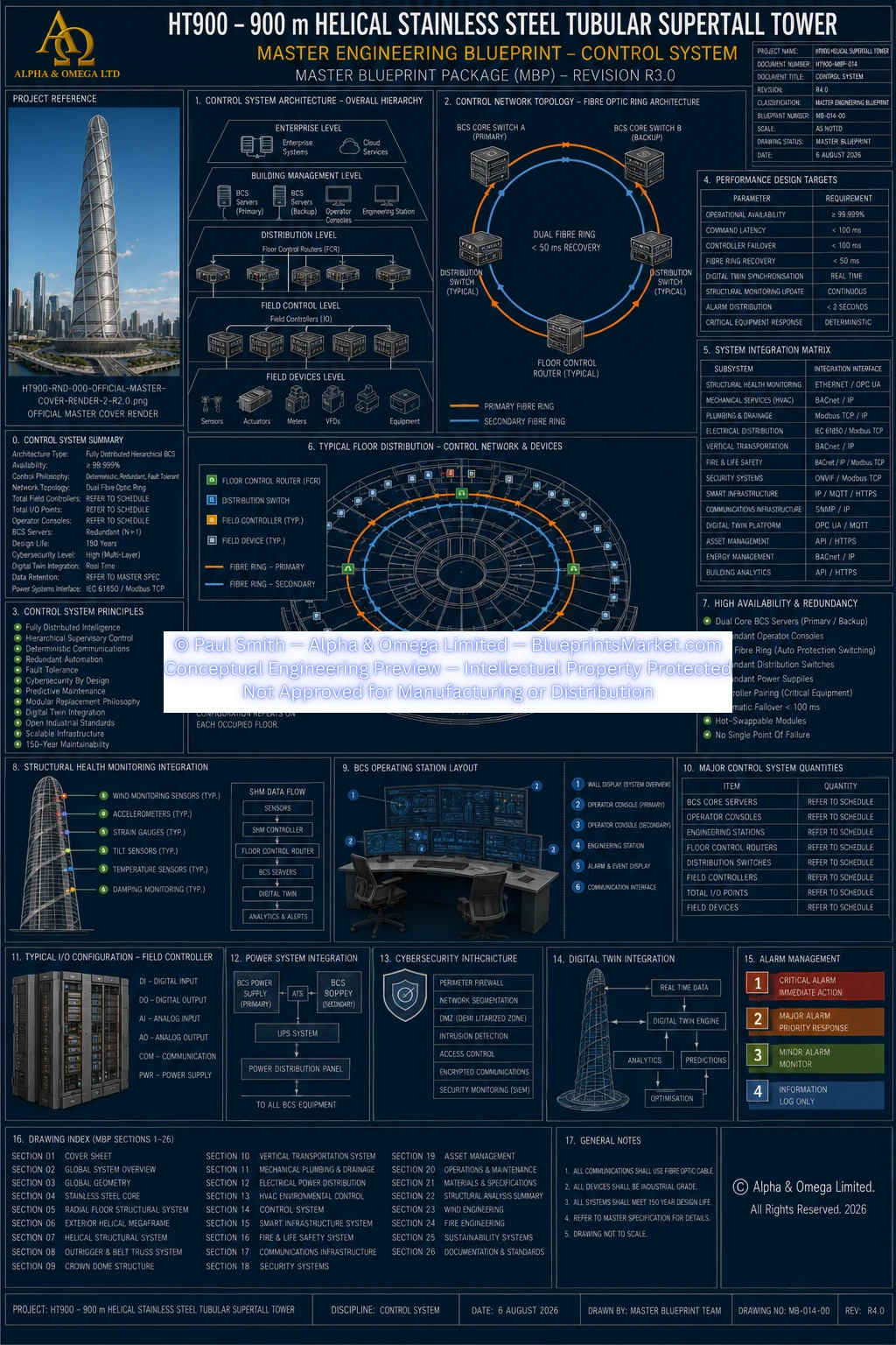
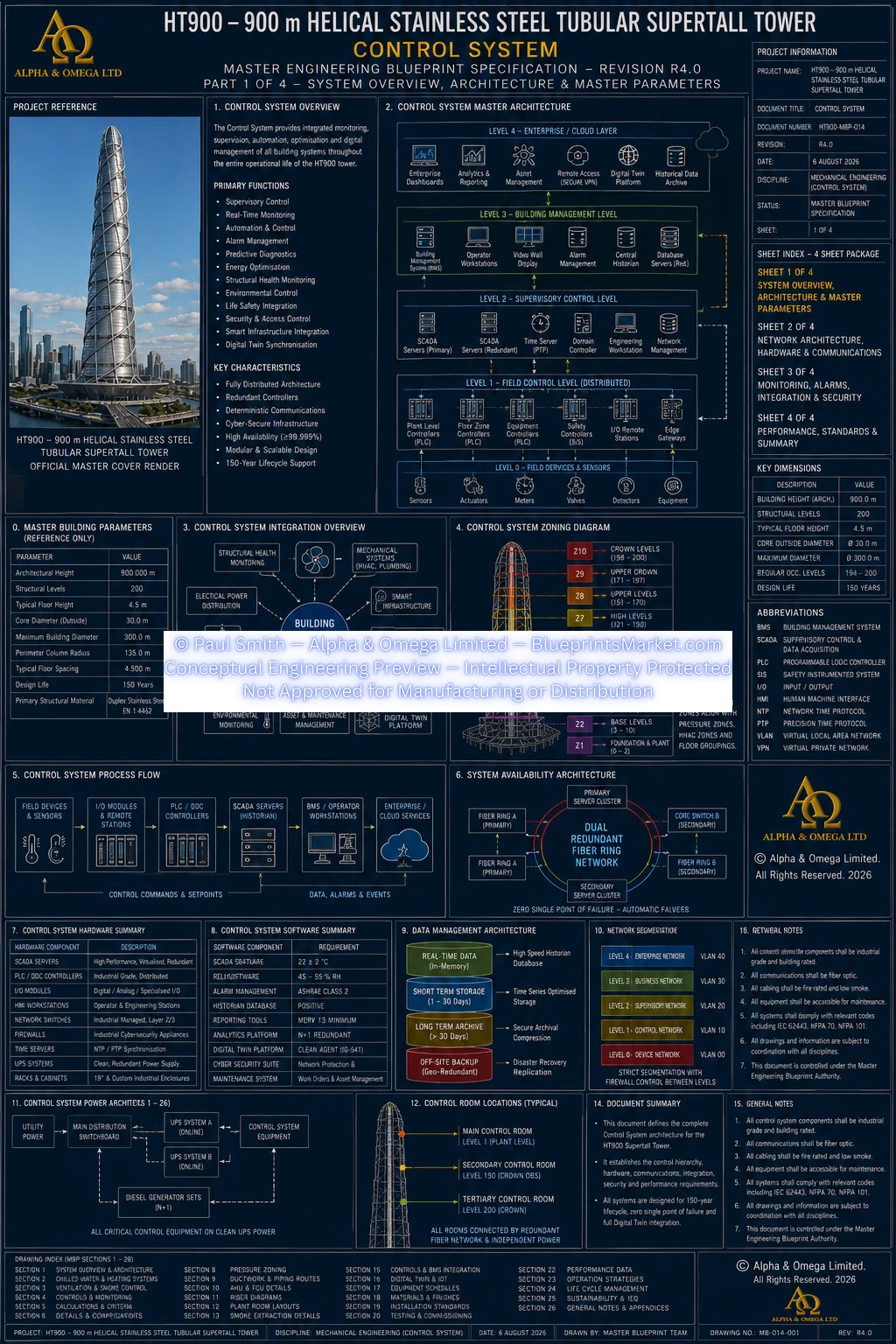
The HT900 Building Control System forms the operational intelligence layer of the 900 metre Helical Stainless-Steel Tubular Supertall Tower.
Rather than operating as a conventional Building Management System limited primarily to HVAC and electrical supervision, the HT900 architecture coordinates the tower's principal engineering, monitoring, operational and lifecycle-management systems through one distributed digital control environment.
Integrated Control Functions
- Mechanical-system supervision
- Electrical-system supervision
- HVAC and environmental control
- Water and drainage monitoring
- Vertical transportation integration
- Fire and life-safety interfaces
- Security-system integration
- Structural Health Monitoring
- Energy management
- Building automation
- Alarm management
- Predictive maintenance
- Digital Twin integration
- Operational analytics
- Lifecycle asset management
2.0 Control-System Design Philosophy
The HT900 control architecture is based on distributed intelligence rather than dependency upon one central controller.
Primary Design Principles
- Fully distributed intelligence
- Hierarchical supervisory control
- Deterministic communications
- Redundant automation
- Fault-tolerant operation
- Cybersecurity by design
- Predictive maintenance
- Modular equipment replacement
- Digital Twin integration
- Enterprise-wide analytics
- Long-term lifecycle management
- Open industrial communication standards
- Scalable infrastructure
Essential equipment is intended to retain autonomous local control during temporary loss of higher-level communications so that failure of a supervisory system does not automatically disable unrelated engineering systems.
3.0 Five-Layer Distributed Control Architecture
The Building Control System is organised into five coordinated control layers.
Layer 1 — Intelligent Field Devices
Distributed instrumentation provides direct measurement, equipment status and actuation throughout the building.
- Temperature sensing
- Pressure sensing
- Flow measurement
- Humidity sensing
- Air-quality monitoring
- Occupancy sensing
- Energy metering
- Water-leak detection
- Structural sensing
- Wind monitoring
- Actuator and equipment interfaces
Layer 2 — Local Equipment Controllers
Major engineering systems use independent local industrial controllers for deterministic real-time operation.
- Closed-loop equipment control
- Equipment sequencing
- Local optimisation
- Equipment protection
- Fault handling
- Functional safety interfaces
- Continuous diagnostics
- Autonomous operation during supervisory communication loss
Layer 3 — Floor Controllers
Each structural floor is coordinated through redundant floor-level control architecture.
- HVAC supervision
- Lighting control
- Environmental monitoring
- Occupancy monitoring
- Energy metering
- Water monitoring
- Local alarm management
- Equipment coordination
Layer 4 — Supervisory Zone Controllers
Groups of floors are coordinated through supervisory zone controllers that manage cross-discipline building operation.
Layer 5 — Building Operations & Enterprise Systems
The highest control layer provides building-wide operational supervision, enterprise analytics, Digital Twin integration, resilience and emergency command capability.
4.0 Ten-Floor Supervisory Control Zoning
The current HT900 control architecture uses ten-floor supervisory control zones.
This replaces the earlier twenty-floor control-zone concept and aligns supervisory control with electrical distribution, communications, Smart Infrastructure, fire engineering, maintenance planning and Digital Twin architecture.
| Zone 1 | Levels 1–10 |
|---|---|
| Zone 2 | Levels 11–20 |
| Zone 3 | Levels 21–30 |
| Zone 4 | Levels 31–40 |
| Zone 5 | Levels 41–50 |
| Continuing | Every subsequent ten-floor group |
Zone-Control Functions
- HVAC optimisation
- Electrical coordination
- Water-system coordination
- Fire-system interfaces
- Lift-zone coordination
- Structural-health monitoring
- Alarm aggregation
- Energy optimisation
- Occupancy analytics
- Predictive maintenance
- Environmental reporting
5.0 Building Operations Centres
The HT900 does not depend upon a single central control room.
Operational command is distributed between a Primary Building Operations Centre and an independent Secondary Emergency Operations Centre.
Primary Building Operations Centre
- Operator supervision
- Engineering supervision
- Digital Twin displays
- Alarm management
- Building analytics
- Security-system integration
- Cybersecurity monitoring
- Maintenance planning
- Incident management
- Communications coordination
Secondary Emergency Operations Centre
The secondary facility is intended to remain operational following loss of the primary command facility and incorporates independent critical infrastructure.
- Independent electrical supply
- Independent UPS support
- Independent communications
- Independent environmental control
- Fire-separated accommodation
- Independent data access
6.0 Resilient Data Centre Architecture
The Building Control System interfaces with Primary and Secondary Data Centres supporting continuous operational data, Digital Twin services, historical records, analytics and disaster recovery.
Primary Data Functions
- Building-management services
- Digital Twin platform
- Historical engineering database
- Alarm services
- Engineering applications
- Asset management
- Predictive maintenance
- Operational analytics
Resilience Strategy
- Primary and secondary facilities
- Active redundancy
- Continuous data replication
- Disaster recovery
- Independent cooling
- Independent UPS
- Independent communications
7.0 Communications & Fibre Backbone
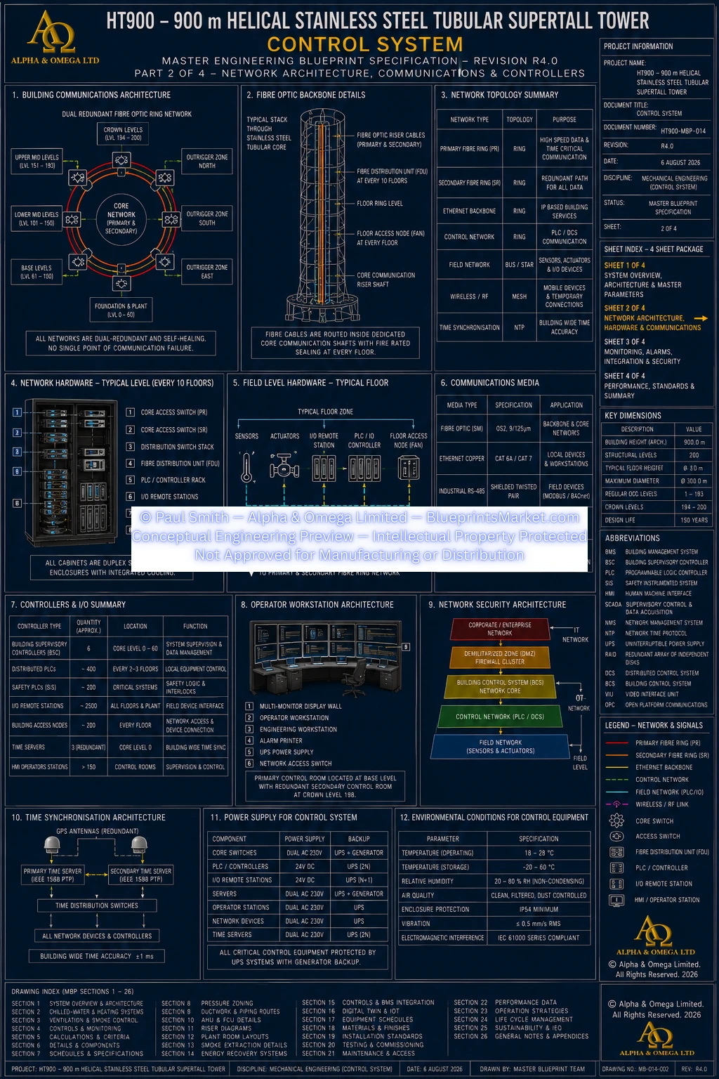
The communications network forms the digital backbone of the Building Control System.
Primary Architecture
- Dual single-mode fibre-optic backbone rings
- Self-healing network topology
- Diverse communications routing
- Independent communications pathways
- Redundant network equipment
- Future expansion capability
Independent Vertical Communications Risers
Three independent communications risers extend through the Stainless Steel Tubular Core.
- Physical separation
- Fire separation
- Maintenance access
- Future expansion
- Redundant routing
The architecture is arranged so that a single communications-path failure does not isolate the entire building.
8.0 Segregated Operational Networks
Critical digital systems are separated through physical and logical network segmentation.
Principal Network Domains
- Life Safety Network
- Building Automation Network
- Structural Monitoring Network
- Security Network
- CCTV Network
- Tenant Data Network
- Digital Twin Data Network
Segmentation is intended to improve operational resilience, cybersecurity, fault containment and system maintainability.
9.0 Open Industrial Communications Architecture
The Building Control System is designed around recognised industrial communication technologies rather than one proprietary closed-control ecosystem.
Supported Communication Families
- BACnet/IP
- OPC UA
- Modbus TCP
- IEC 61850 where applicable
- MQTT
- SNMP
Protocol Selection Objectives
- Deterministic performance
- Cybersecurity
- Interoperability
- Vendor independence
- Long-term lifecycle support
10.0 Industrial PLC & Distributed I/O Architecture
Mission-critical building systems use industrial PLC and distributed I/O architecture designed for continuous operation, modular replacement and fault isolation.
PLC Engineering Principles
- Industrial reliability
- Redundant processing
- Hot-standby capability
- Online diagnostics
- Secure firmware management
- Configuration management
- Remote maintenance capability
- Modular equipment replacement
Distributed I/O Functions
- Hot-swappable modules
- Local diagnostics
- Redundant communications
- Fault isolation
- Maintenance bypass
- Future expansion capability
Detailed controller hardware, memory capacities, I/O quantities and equipment dimensions remain implementation-level engineering decisions and are not fixed by this public overview.
11.0 Human–Machine Interface & Operator Systems
The Human–Machine Interface provides role-based operational access to the HT900 Building Control System.
Authorised Operational Roles
- Building operators
- Engineering staff
- Mechanical engineers
- Electrical engineers
- Structural engineers
- Fire-safety personnel
- Security personnel
- Maintenance technicians
- Asset managers
- System administrators
Operator Functions
- Real-time equipment status
- Alarm monitoring
- Trend analysis
- Digital Twin visualisation
- Maintenance management
- Historical engineering analysis
- Energy monitoring
- Structural-health dashboards
Access permissions are assigned according to operational role, responsibility and cybersecurity policy.
12.0 Integrated Building-System Control
The Building Control System provides coordinated supervisory management across the principal engineering disciplines.
Mechanical Systems
- HVAC systems
- Air Handling Units
- Chiller systems
- Pump systems
- Cooling systems
- Water-treatment systems
- Pressurisation systems
- Smoke-control systems
- Exhaust systems
Electrical Systems
- Utility supply monitoring
- Medium-voltage distribution
- Low-voltage distribution
- UPS systems
- Emergency generation
- Energy metering
- Power-quality monitoring
- Load coordination
Plumbing & Water Systems
- Water supply
- Drainage
- Pressure systems
- Storage systems
- Water-quality monitoring
- Pump operation
- Leak detection
Vertical Transportation
- Passenger lift integration
- Service lift integration
- Firefighter lift integration
- Traffic-management interfaces
- Operational-status monitoring
13.0 Environmental & Energy Optimisation
The control architecture coordinates environmental performance and energy usage throughout the building.
Optimisation Functions
- Occupancy-based environmental control
- Demand-controlled ventilation
- Plant optimisation
- Pump optimisation
- Lighting optimisation
- Energy metering
- Renewable-energy coordination
- Energy-storage coordination
- Operational performance analytics
AI-Assisted Analytics
Advanced analytics may assist engineering operations through:
- Occupancy prediction
- Cooling-load forecasting
- Energy optimisation
- Equipment scheduling
- Demand-response optimisation
- Maintenance prediction
AI-assisted systems are intended to support rather than replace professional engineering judgement.
14.0 Alarm & Event Management
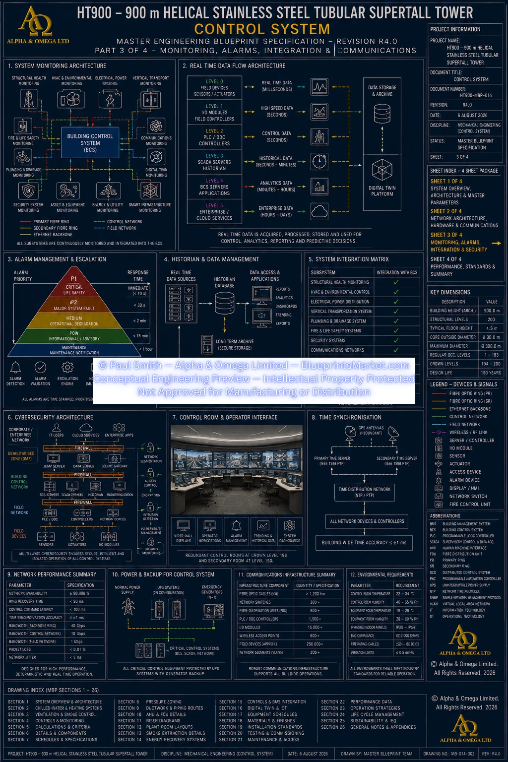
Building-wide alarm management provides prioritised notification, operator guidance and historical event recording across the integrated engineering systems.
Alarm Categories
- Life-safety alarms
- Critical-equipment alarms
- Maintenance notifications
- Operational information
Alarm-Management Functions
- Priority filtering
- Duplicate-event reduction
- Event correlation
- Alarm suppression where appropriate
- Operator acknowledgement
- Escalation logic
- Corrective-action recording
- Historical analysis
Historical alarm information supports root-cause analysis, reliability improvement, maintenance planning and failure prediction.
15.0 Digital Twin Integration
The Building Control System integrates continuously with the HT900 Digital Twin platform.
Digital Twin Functions
- Real-time building model
- Equipment monitoring
- Structural monitoring
- Environmental analysis
- Energy analysis
- Maintenance planning
- Asset management
- Lifecycle analysis
Continuous Data Sources
- Industrial controllers
- Structural sensors
- HVAC systems
- Electrical systems
- Plumbing systems
- Vertical transportation
- Security systems
- Fire systems
Predictive Analytics
- Equipment-degradation analysis
- Structural-movement analysis
- Energy forecasting
- Occupancy modelling
- Lifecycle prediction
- Maintenance optimisation
16.0 Structural Health Monitoring Integration
Structural Health Monitoring is a core function of the HT900 Building Control System rather than an isolated monitoring package.
Principal Monitored Structural Systems
- Stainless Steel Tubular Core
- Exterior Helical Megaframe
- Outrigger systems
- Belt-Truss systems
- Foundation
- Seismic-isolation system
- Crown Dome Structure
Typical Structural Instrumentation
- Strain monitoring
- Acceleration monitoring
- Tilt monitoring
- Displacement monitoring
- Wind monitoring
- Temperature monitoring
- Vibration monitoring
Monitoring Objectives
- Structural-movement assessment
- Wind-response assessment
- Seismic-response assessment
- Long-term deformation monitoring
- Fatigue monitoring
- Structural performance verification
- Predictive maintenance
17.0 Cybersecurity Architecture
Cybersecurity is integrated into the Building Control System using a defence-in-depth philosophy.
Security Objectives
- Confidentiality
- Integrity
- Availability
- Authentication
- Accountability
- Operational resilience
Cybersecurity Principles
- Zero Trust architecture
- Device authentication
- Role-based permissions
- Multi-factor authentication where required
- Network segmentation
- Secure communications
- Certificate management
- Secure firmware management
- Security patch management
- Vulnerability assessment
- Security audit logging
- Incident-response planning
- Backup and disaster recovery
Final cybersecurity controls are established according to project requirements, applicable regulations and the approved information security framework.
18.0 Redundancy, Fault Tolerance & Resilience
The HT900 control architecture is designed to eliminate unnecessary single points of failure and maintain essential building functions during equipment or communications faults.
Redundancy Strategy
- Redundant PLC processing
- Dual fibre communications rings
- Redundant power supplies
- Redundant UPS systems
- Redundant servers
- Redundant storage systems
- Primary and Secondary Data Centres
- Redundant network switches
- Primary and Secondary Operations Centres
Automatic Fault Management
- Fault detection
- Fault isolation
- Alarm generation
- Standby controller activation
- Communications rerouting
- Event logging
- Operator notification
- Digital Twin synchronisation
Degraded Operating Modes
Where full redundancy is temporarily unavailable, predefined degraded modes are intended to preserve critical services and life-safety functionality while isolating affected equipment.
19.0 Conceptual Control-System Performance Targets
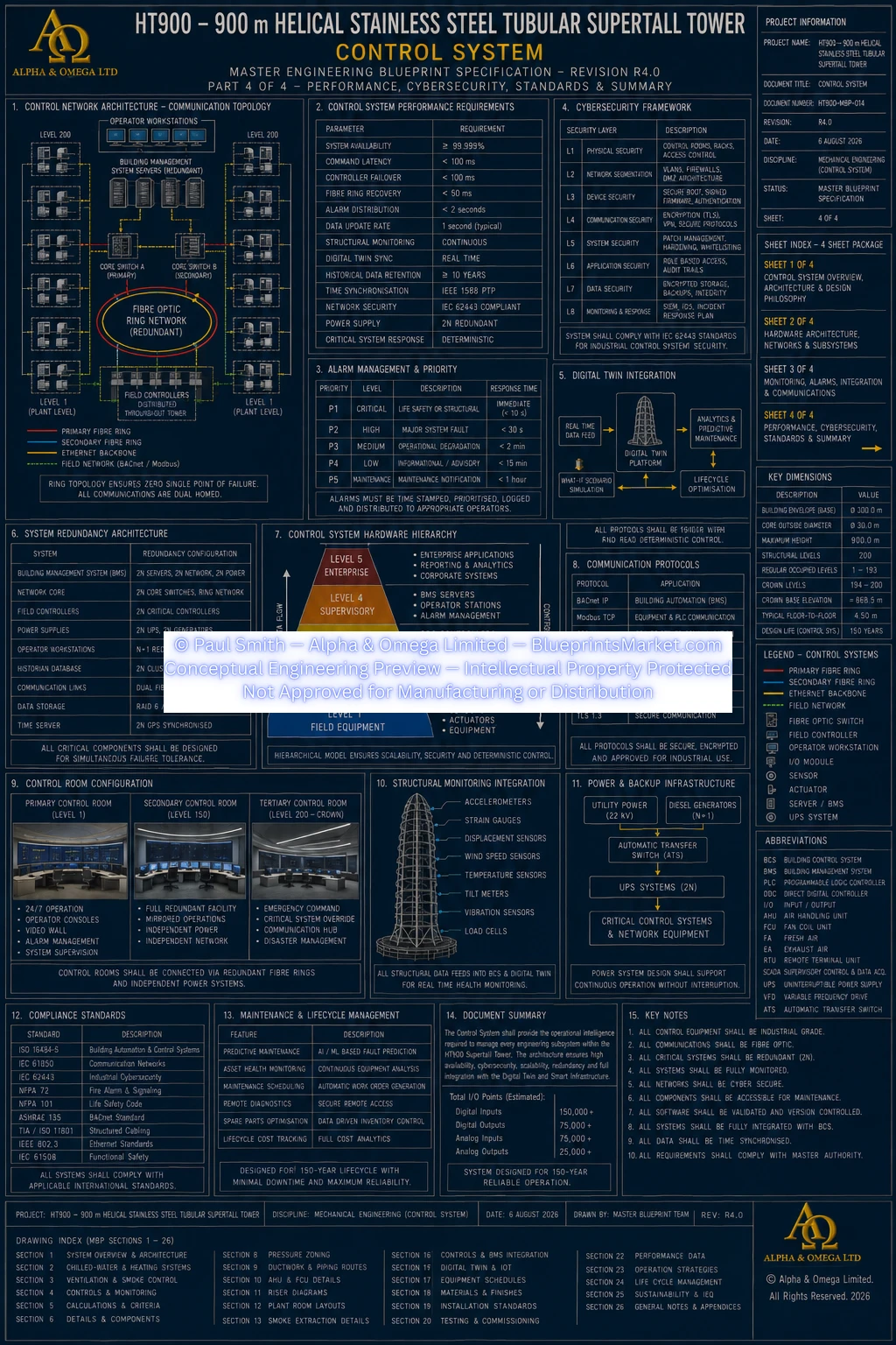
The following values form conceptual control-system performance objectives within the governing specification.
| Operational Availability Target | ≥ 99.999% |
|---|---|
| Command Latency Target | < 100 ms |
| Controller Failover Target | < 100 ms |
| Fibre Ring Recovery Target | < 50 ms |
| Structural Monitoring | Continuous |
| Digital Twin Synchronisation | Real-time target |
These are conceptual engineering performance requirements and require validation during detailed system engineering, Factory Acceptance Testing, Site Acceptance Testing and final commissioning.
20.0 Installation, Testing & Commissioning
The control architecture follows the wider HT900 modular engineering philosophy and is progressively tested from fabrication through final integrated building commissioning.
Principal Commissioning Stages
- Multidisciplinary coordination
- Control-panel fabrication
- Factory Acceptance Testing
- Communications infrastructure installation
- Industrial controller installation
- Distributed I/O installation
- Field-device installation
- Network commissioning
- Control-software installation
- Integration testing
- Cybersecurity validation
- Digital Twin integration
- Site Acceptance Testing
- Integrated system commissioning
- Asset registration
- Operational handover
Integrated Commissioning
- HVAC systems
- Electrical systems
- Mechanical systems
- Plumbing systems
- Vertical transportation
- Fire & Life Safety
- Security systems
- Smart Infrastructure
- Digital Twin
- Structural Health Monitoring
21.0 Lifecycle Asset & Technology Strategy
The HT900 control architecture distinguishes between long-life permanent infrastructure and replaceable electronic technology.
Long-Life Infrastructure
- Communications risers
- Fibre-optic pathways
- Equipment rooms
- Communications shafts
- Cable support infrastructure
- Permanent mounting systems
- Approved structural penetrations
Planned Replaceable Electronic Assets
- PLC processors
- Remote I/O modules
- Industrial computers
- Servers
- Storage systems
- Operator workstations
- Displays
- Network switches
- Firewalls
- Wireless infrastructure
- Sensors
- Controllers
- Power supplies
- UPS electronics
Electronic systems are intended to be replaced and upgraded over the building lifecycle without requiring fundamental reconstruction of the permanent communications infrastructure.
22.0 Future Technology Integration
The permanent control infrastructure is intended to support future generations of operational technology throughout the building lifecycle.
Future Integration Concepts
- AI-assisted optimisation
- Advanced Digital Twin analytics
- Smart-grid integration
- Expanded renewable-energy integration
- Robotic systems
- Autonomous inspection systems
- Future industrial communication protocols
- Expanded sensor networks
- Future predictive-maintenance technologies
23.0 Principal System Interfaces
The Control System interfaces directly with the major HT900 engineering systems.
- Stainless Steel Tubular Core monitoring
- Mechanical, Plumbing & Drainage System
- Electrical Power Distribution System
- HVAC & Environmental Control System
- Vertical Transportation System
- Smart Infrastructure System
- Fire & Life Safety System
- Communications Infrastructure
- Security Systems
- Structural Health Monitoring
- Foundation & Isolation monitoring
- Crown systems
- Hybrid Tuned Mass Damping System
- Asset-management systems
- Maintenance & Access Systems
- Digital Twin platform
24.0 Control-System Engineering Logic Summary
- The HT900 uses a five-layer distributed control architecture rather than one central controller.
- Local equipment controllers retain autonomous operating capability during temporary supervisory communication loss.
- Redundant floor controllers and ten-floor supervisory zones distribute operational intelligence throughout the 200-level tower.
- Primary and Secondary Building Operations Centres provide resilient building-wide command capability.
- Primary and Secondary Data Centres provide operational data, analytics, disaster recovery and Digital Twin services.
- Dual fibre-optic rings and segregated operational networks provide resilient communications.
- Structural Health Monitoring continuously integrates the physical tower structure into the operational control architecture.
- The Digital Twin combines operational, structural, environmental, energy and lifecycle information into a coordinated engineering model.
- Cybersecurity by design protects critical operational technology through authentication, segmentation, controlled access and defence-in-depth principles.
- Permanent pathways and infrastructure are separated from planned replaceable electronic assets, allowing future technology upgrades without rebuilding the tower's permanent communications architecture.
25.0 Professional Engineering Notice
The HT900 Control System forms part of the HT900 conceptual Master Blueprint Package.
This public page summarises the principal control-system architecture, control hierarchy, supervisory zoning, communications strategy, operational redundancy, Digital Twin integration, Structural Health Monitoring, cybersecurity philosophy and lifecycle engineering strategy.
Detailed controller hardware, processor specifications, server capacities, individual I/O counts, sensor quantities, exact network addressing, software logic, control sequences, electrical wiring, cabinet dimensions, device configurations, cybersecurity configurations and implementation-level control engineering are intentionally not presented as public-page specifications.
Those details remain within the applicable HT900 technical documentation or require development during subsequent project-specific detailed engineering.
Any real-world implementation requires complete controls engineering, network engineering, cybersecurity design, electrical coordination, fire and life-safety integration, software development, Factory Acceptance Testing, Site Acceptance Testing, commissioning, regulatory review and certification by appropriately qualified and licensed engineering professionals.
HT900-MBP-014 — CONTROL SYSTEM
Copyright — Alpha & Omega Limited
All blueprint files, CAD parameters, architectural concepts, engineering specifications, and written content are the exclusive intellectual property of Alpha & Omega Limited. No part of the Stainless‑Steel Skyscraper Blueprint Package may be reproduced, distributed, or adapted without written consent.
Licensing, Copyright & Patent Restrictions
This engineering system and all associated blueprint materials, CAD files, diagrams, schematics, dimensional tables, and technical narratives are licensed, not sold, and remain the exclusive intellectual property of Alpha & Omega Limited.
This product is not eligible for patenting by any purchaser, user, organization, or third party. Patent filings, provisional patents, utility models, derivative patents, reverse‑engineering for patent purposes, and intellectual property claims are strictly prohibited.
Redistribution, resale, sublicensing, public posting, dataset inclusion, or any form of unauthorized duplication of blueprint materials, CAD files, diagrams, or engineering concepts is strictly prohibited. No license tier grants ownership, patent rights, or rights to file for intellectual property protection.
All architectural & engineering systems are conceptual and require full professional engineering validation before any real‑world use, construction, prototyping, or structural implementation.
Full legal details are available in the Terms & Conditions .