
Foundation & Substructure System
HT900 — Inverted-Dome Foundation, Seismic Isolation & Deep Foundation Architecture
1.0 System Overview
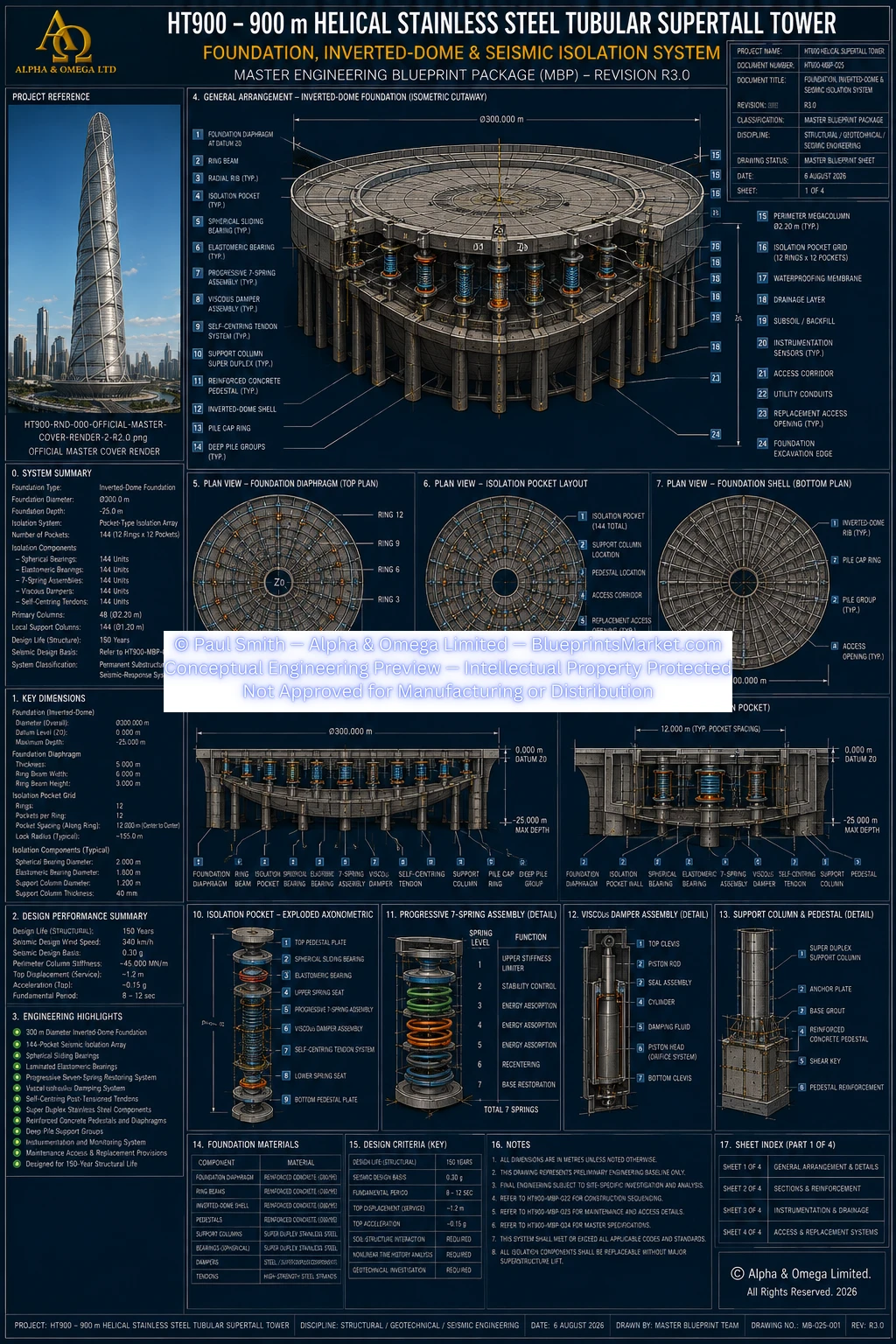
The HT900 Foundation & Substructure System provides the complete conceptual load-transfer and seismic-isolation architecture for the 900-metre Helical Stainless-Steel Tubular Supertall Tower.
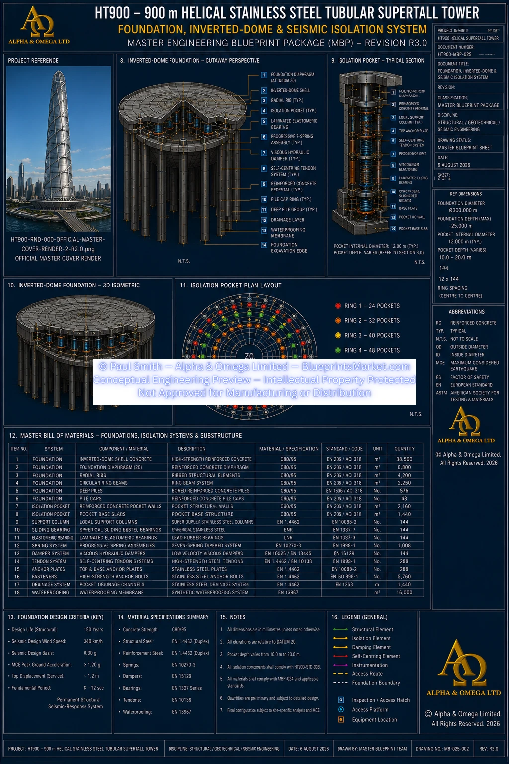
The system combines a large inverted-dome reinforced-concrete foundation, a distributed seismic-isolation pocket array, local stainless-steel support interfaces, deep foundation support, waterproofing, drainage, monitoring and long-term maintenance access.
The foundation is designed to transfer loads from the tubular stainless-steel superstructure into the ground while also allowing controlled movement and energy dissipation during seismic events.
2.0 Master Foundation Parameters
| Tower Architectural Height | 900 m |
|---|---|
| Structural Levels | 200 |
| Foundation Form | Fully Concave Inverted Dome |
| Foundation Diameter | 300 m |
| Foundation Radius | 150 m |
| Approximate Maximum Depth | 25 m below foundation datum |
| Central Tubular Core Diameter | 30 m |
| Primary Structural Sectors | 48 |
| Seismic Isolation Pockets | 144 |
| Foundation Support Groups | 144 |
| Deep Piles per Support Group | 8 |
| Total Deep Piles | 1,152 |
3.0 Foundation System Architecture
The complete foundation and seismic-isolation system is organised into five coordinated structural layers.
Layer 1 — Stainless-Steel Superstructure
- Continuous tubular stainless-steel structural core
- 48 perimeter stainless-steel megacolumns
- Radial floor diaphragms
- Exterior helical megaframe
- Outrigger and belt-truss systems
- Foundation-level structural transfer framing
Layer 2 — Foundation Diaphragm & Support Interfaces
- Reinforced foundation diaphragm
- Central tubular-core interface
- Perimeter structural interfaces
- Local support-column nodes
- Load-spreading zones
- Inspection and maintenance access
- Movement clearances
Layer 3 — Seismic Isolation Pocket System
- Local stainless-steel support interfaces
- Sliding and elastomeric bearing systems
- Progressive restoring systems
- Hydraulic energy-dissipation systems
- Self-centring systems
- Reinforced structural pedestals
- Drainage and monitoring provisions
Layer 4 — Inverted-Dome Foundation
- Variable-thickness reinforced-concrete dome
- Central load-distribution zone
- Intermediate dome shell
- Outer compression-ring zone
- 144 pile-cap interfaces
- Waterproofing and drainage systems
- Inspection provisions
Layer 5 — Deep Foundation
- 144 pile-cap support groups
- Eight piles per support group
- 1,152 total deep piles
- Load transfer into competent founding strata
- Foundation monitoring and testing provisions
4.0 Inverted-Dome Foundation
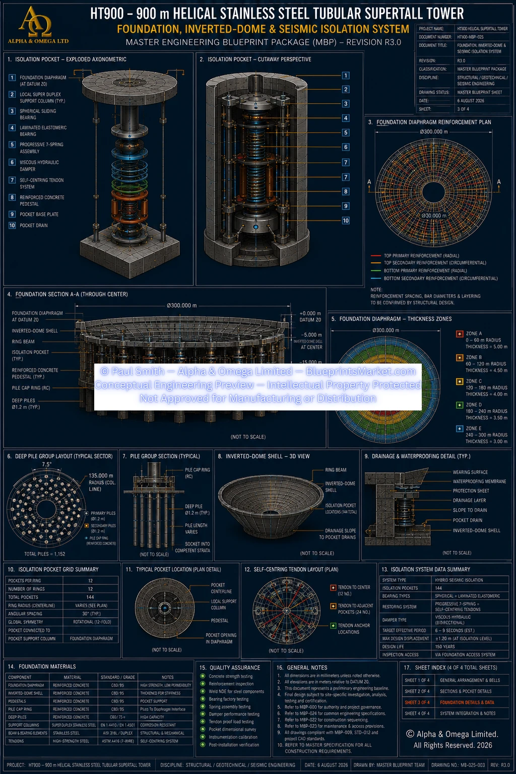
The primary substructure is a 300-metre-diameter concave inverted reinforced-concrete dome extending approximately 25 metres below the foundation datum.
Rather than using a uniform foundation thickness, the updated HT900 baseline uses a variable-thickness structural philosophy.
The dome becomes progressively more substantial through high-demand structural regions such as the central load-transfer zones, intermediate transfer zones and the outer compression-ring region.
Final thicknesses are subject to finite-element analysis, soil-structure interaction, punching-shear checks, crack-control requirements, seismic analysis and site-specific geotechnical data.
5.0 Seismic Isolation Pocket Array
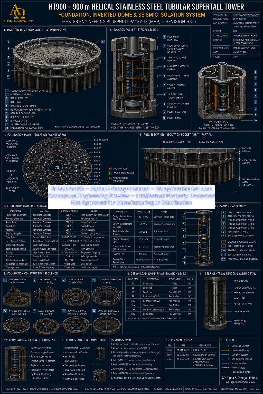
The HT900 foundation incorporates 144 seismic-isolation pocket assemblies.
The preliminary arrangement uses four concentric support groups distributed across the inverted-dome foundation.
| Inner Pocket Group | 24 assemblies |
|---|---|
| Intermediate Pocket Group 1 | 32 assemblies |
| Intermediate Pocket Group 2 | 40 assemblies |
| Outer Pocket Group | 48 assemblies |
| Total | 144 assemblies |
The outer 48-pocket arrangement aligns naturally with the HT900 48-sector structural grid and perimeter structural system.
Final inner-ring positions would be coordinated with the tubular-core footprint, radial floor grid, pile-cap geometry, dome curvature, maintenance access and drainage requirements.
6.0 Seismic Isolation Strategy
The isolation system is intended to partially decouple the superstructure from ground movement while maintaining structural stability, gravity-load support and post-event recoverability.
The system performs five coordinated functions:
- Support permanent gravity loads
- Permit controlled horizontal movement
- Dissipate dynamic energy
- Provide progressive restoring force
- Assist the structure in returning toward its neutral position
These functions are distributed across multiple engineered systems rather than relying on a single isolation component.
7.0 Isolation-System Components
Each conceptual isolation support assembly integrates several coordinated systems.
- Local stainless-steel structural support interface
- Primary bearing system
- Spherical sliding bearing
- Laminated elastomeric bearing
- Progressive multi-spring restoring system
- Hydraulic viscous damping system
- Self-centring tendon system
- Structural reaction plates
- Reinforced-concrete pedestal
- Pile-cap support system
- Deep foundation interface
- Drainage, waterproofing and monitoring systems
Each subsystem performs a different engineering role and is not intended to substitute for the others.
8.0 Foundation Load-Path Philosophy
Gravity Load Path
Occupancy and structural loads are transferred through the floor diaphragms and radial framing into the tubular stainless-steel core and exterior megaframe.
Loads then pass through the foundation diaphragm, local support interfaces, primary bearing system, reinforced pedestals, pile caps and deep foundation into competent founding strata.
Seismic Load Path
Ground movement is transmitted through the deep piles and inverted-dome foundation into the isolation support assemblies.
Sliding and elastomeric bearing systems, restoring components, damping systems and self-centring elements then manage relative movement between the foundation and the superstructure.
Energy Dissipation
Hydraulic damping systems dissipate part of the kinetic energy generated by transient structural movement, helping reduce oscillation and peak movement.
9.0 Deep Foundation System
The HT900 baseline establishes 144 deep-foundation support groups.
Each support group uses:
- One pile-cap structural interface
- Eight deep piles
- Connection into the inverted-dome foundation
- Local structural reinforcement
This produces a total of: 1,152 deep piles.
Final pile diameter, depth, type and capacity are site-dependent and would be determined by geotechnical investigation, load testing, settlement analysis and foundation engineering.
10.0 Material Philosophy
| Primary Superstructure | Duplex Stainless Steel EN 1.4462 |
|---|---|
| Selected High-Demand Isolation Components | Qualified Super Duplex Stainless Steel |
| Foundation Structure | High-Strength Reinforced Concrete |
| Spring Systems | Qualified High-Fatigue Spring Steel |
| Damping Components | High-Strength Engineered Alloy Materials |
| Bearing Interfaces | Stainless Steel, Bearing Steel and Engineered Sliding Materials |
| Waterproofing | Multi-Layer Chemically Compatible Membrane System |
11.0 Waterproofing & Drainage
Because the foundation extends below ground and incorporates numerous inspection and isolation chambers, groundwater control is treated as a permanent engineering requirement.
The system incorporates:
- Multi-layer waterproofing membranes
- Protected construction joints
- Drainage cavities
- Controlled drainage networks
- Inspection points
- Pumped drainage where required
- Water-ingress monitoring
Waterproofing is coordinated with structural movement, maintenance access and the seismic-isolation system.
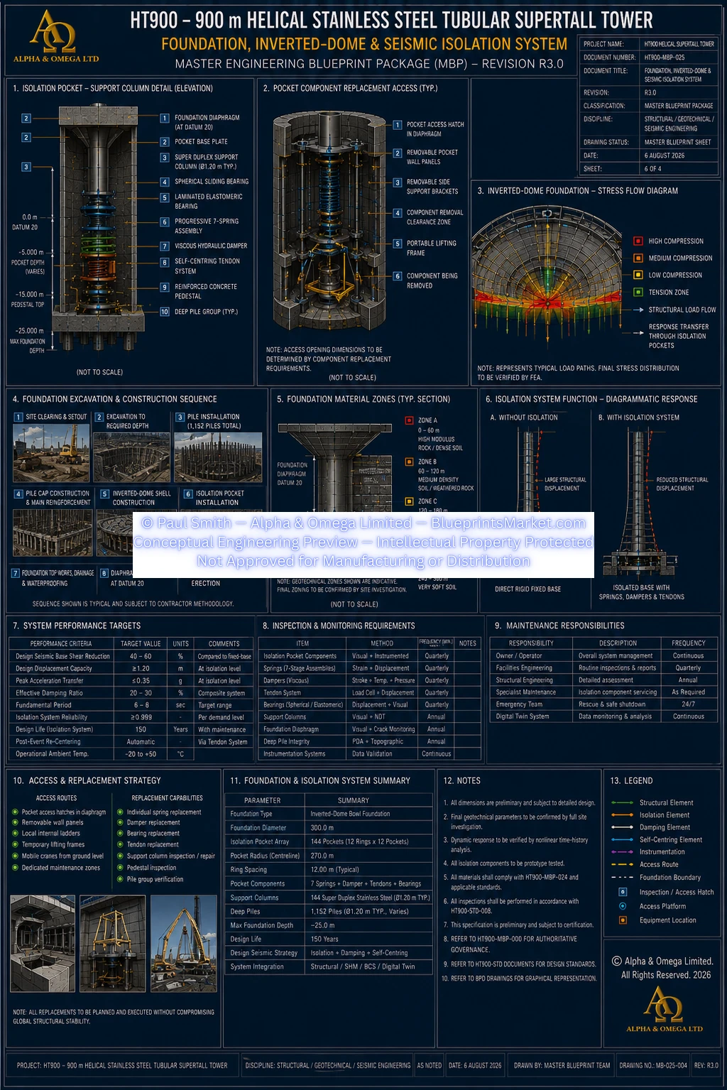
12.0 Inspection, Monitoring & Replaceability
The HT900 foundation philosophy includes permanent provisions for inspection and lifecycle maintenance.
Isolation components are intended to remain accessible for monitoring, inspection and controlled replacement where practical.
Monitoring provisions may include:
- Structural strain monitoring
- Displacement monitoring
- Foundation movement monitoring
- Bearing-condition monitoring
- Damper-condition monitoring
- Tendon-force monitoring
- Temperature monitoring
- Water-ingress monitoring
- Digital Twin lifecycle records
13.0 Structural Redundancy
The foundation is designed around multiple coordinated load-transfer mechanisms rather than a single structural support path.
Redundancy is provided through:
- 144 distributed support locations
- Multiple concentric support groups
- Deep-pile groups beneath individual support locations
- Continuous inverted-dome load distribution
- Multiple bearing systems
- Independent damping systems
- Independent restoring-force systems
- Self-centring components
- Continuous structural-health monitoring
14.0 Principal Engineering Considerations
A foundation system of this scale requires detailed analysis of several interacting structural and geotechnical effects.
- Differential settlement
- Soil-structure interaction
- Groundwater pressure
- Foundation uplift
- Punching shear
- Foundation cracking
- Seismic displacement
- Isolation-system overtravel
- Structural fatigue
- Long-term component ageing
- Maintenance access
- Construction-stage behaviour
These effects would require site-specific nonlinear analysis and geotechnical verification before any real-world implementation.
15.0 Structural Integration
The foundation and seismic-isolation system is directly integrated with the complete HT900 superstructure.
Primary Interfaces
- Stainless-Steel Tubular Core
- 48 Perimeter Megacolumns
- Radial Floor Structural System
- Exterior Helical Megaframe
- Helical Structural System
- Outrigger & Belt-Truss System
- Structural Connection System
- Structural Health Monitoring
- Maintenance & Access Systems
16.0 Engineering Summary
The HT900 Foundation & Substructure System provides a coordinated conceptual foundation architecture for the 900-metre Helical Stainless-Steel Tubular Supertall Tower.
The system combines a 300-metre inverted-dome foundation, 144 distributed seismic-isolation assemblies, 144 deep-foundation support groups and 1,152 total deep piles.
Its engineering philosophy separates gravity-load support, seismic movement, energy dissipation and restoring force into coordinated structural subsystems.
This architecture creates a continuous load-transfer path from the tubular stainless-steel superstructure through the isolation system, inverted-dome foundation and deep foundation into competent founding strata.
17.0 Conceptual Engineering Notice
This public page provides a high-level overview of the HT900 Foundation, Inverted-Dome & Seismic Isolation System.
Detailed pocket geometry, spring schedules, bearing specifications, damper characteristics, tendon forces, fastener schedules, reinforcement layouts, pile capacities, foundation thickness schedules, component tolerances and proprietary construction details are contained within the licensed HT900 Master Blueprint Package and are not reproduced on this public page.
Any real-world construction would require site-specific geotechnical investigation, seismic-hazard analysis, soil-structure interaction modelling, nonlinear structural analysis, foundation testing, prototype isolation-system testing, regulatory review and certification by appropriately qualified and licensed engineering professionals.
HT900-MBP-025 — FOUNDATION, INVERTED DOME & SEISMIC ISOLATION SYSTEM
Copyright — Alpha & Omega Limited
All blueprint files, CAD parameters, architectural concepts, engineering specifications, and written content are the exclusive intellectual property of Alpha & Omega Limited. No part of the Stainless‑Steel Skyscraper Blueprint Package may be reproduced, distributed, or adapted without written consent.
Licensing, Copyright & Patent Restrictions
This engineering system and all associated blueprint materials, CAD files, diagrams, schematics, dimensional tables, and technical narratives are licensed, not sold, and remain the exclusive intellectual property of Alpha & Omega Limited.
This product is not eligible for patenting by any purchaser, user, organization, or third party. Patent filings, provisional patents, utility models, derivative patents, reverse‑engineering for patent purposes, and intellectual property claims are strictly prohibited.
Redistribution, resale, sublicensing, public posting, dataset inclusion, or any form of unauthorized duplication of blueprint materials, CAD files, diagrams, or engineering concepts is strictly prohibited. No license tier grants ownership, patent rights, or rights to file for intellectual property protection.
All architectural & engineering systems are conceptual and require full professional engineering validation before any real‑world use, construction, prototyping, or structural implementation.
Full legal details are available in the Terms & Conditions .