
1. Assembly & Fastener System Overview
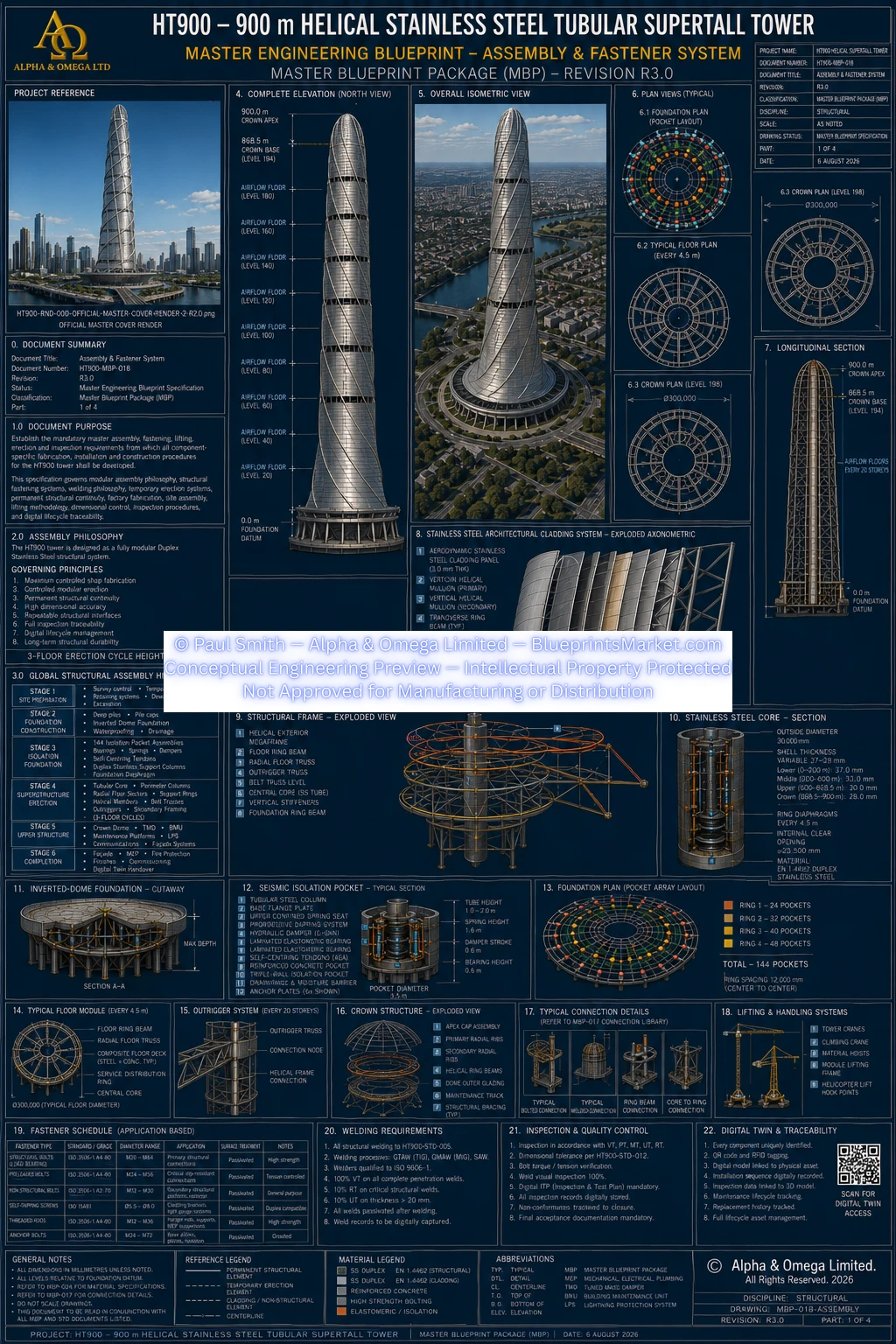
The HT900 R3.0 Assembly & Fastener System establishes the conceptual engineering methodology for the fabrication, transportation, erection, fastening, welding, inspection and lifecycle management of the primary structural systems within the 900 metre Helical Stainless-Steel Tubular Supertall Tower.
The system is based on a fully modular Duplex Stainless Steel structural philosophy intended to maximise controlled factory fabrication while maintaining permanent structural continuity, repeatable interfaces, high dimensional accuracy and long-term inspection accessibility.
Primary Assembly Principles
- Maximum controlled shop fabrication
- Controlled modular erection
- Permanent structural continuity
- High dimensional accuracy
- Repeatable structural interfaces
- Comprehensive inspection traceability
- Long-term structural durability
- Lifecycle maintenance planning
2. Global Structural Assembly Hierarchy
Construction of the HT900 concept is organised through a staged assembly sequence progressing from the deep foundation and seismic-isolation system through the primary superstructure, crown structure and integrated building systems.
Principal Assembly Stages
- Site preparation and survey control
- Deep foundation and inverted-dome foundation construction
- Seismic-isolation foundation installation
- Primary superstructure erection
- Upper structure and Crown Dome installation
- Façade, building services and final system integration
- Testing, inspection and commissioning
Foundation & Isolation Stage
- Deep-pile foundation system
- Pile-cap interfaces
- Inverted Dome Foundation
- 144 Isolation Pocket Assemblies
- Seismic bearing systems
- Progressive spring assemblies
- Hydraulic damping systems
- Self-centering components
- Foundation diaphragm
3. Modular Superstructure Erection Philosophy
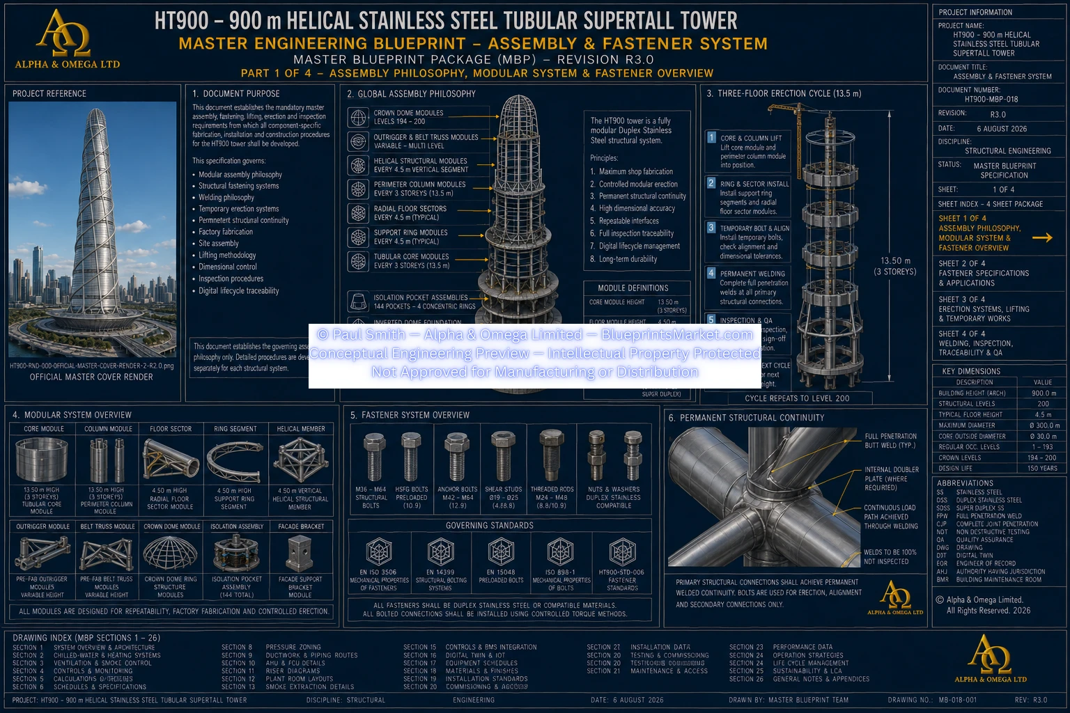
The HT900 tower is designed around coordinated modular erection rather than lifting entire structural floors as complete assemblies.
The governing superstructure erection philosophy uses coordinated 13.5 metre three-floor erection cycles.
Three-Floor Erection Cycle
- Tubular Core Modules
- Perimeter Column Modules
- Radial Floor Sectors
- Concentric Support Ring Segments
- Secondary structural framing
- Helical Structural Members
- Belt-Truss assemblies
- Outrigger assemblies where applicable
Structural floors are assembled progressively from segmented components after primary vertical and radial structural modules have been positioned.
4. Primary Structural Module Families
The HT900 modular system divides the primary structure into transportable and erectable structural module families.
Core Modules
| Typical Module Height | 13.5 metres |
|---|---|
| Structural Levels | 3 levels per typical module cycle |
Radial Floor Assemblies
- 48 Primary Radial Sectors per floor
- Segmented Primary Radial Trusses
- Segmented Concentric Support Rings
- Secondary framing
- Stainless structural deck
- Composite concrete topping
Helical Structural Modules
Typical helical structural modules are coordinated with the 13.5 metre three-floor erection cycle.
Outrigger Assemblies
- Approximately 8–9 metre structural depth
- Typically occupy approximately two structural levels
- Eight primary outrigger arms
- Integrated with the central core and perimeter megaframe
Crown Modules
- Crown rib segments
- Helical crown members
- Structural ring segments
- Structural node assemblies
5. Transport & Lifting Philosophy
HT900 structural modules are divided into practical transport and lifting categories rather than attempting to move or lift complete structural floors as single units.
| Standard Structural Modules | Typical target lift mass: 15–35 tonnes |
|---|---|
| Large Column Modules | Typical target lift mass: 50–120 tonnes |
| Heavy Transfer / Node Modules | Up to approximately 150 tonnes |
| Complete Structural Floor | Never lifted as one module |
Final lifting arrangements remain subject to project-specific lifting engineering, crane selection, rigging analysis, centre-of-gravity verification and site wind conditions.
6. Hybrid Fastener & Structural Connection Philosophy
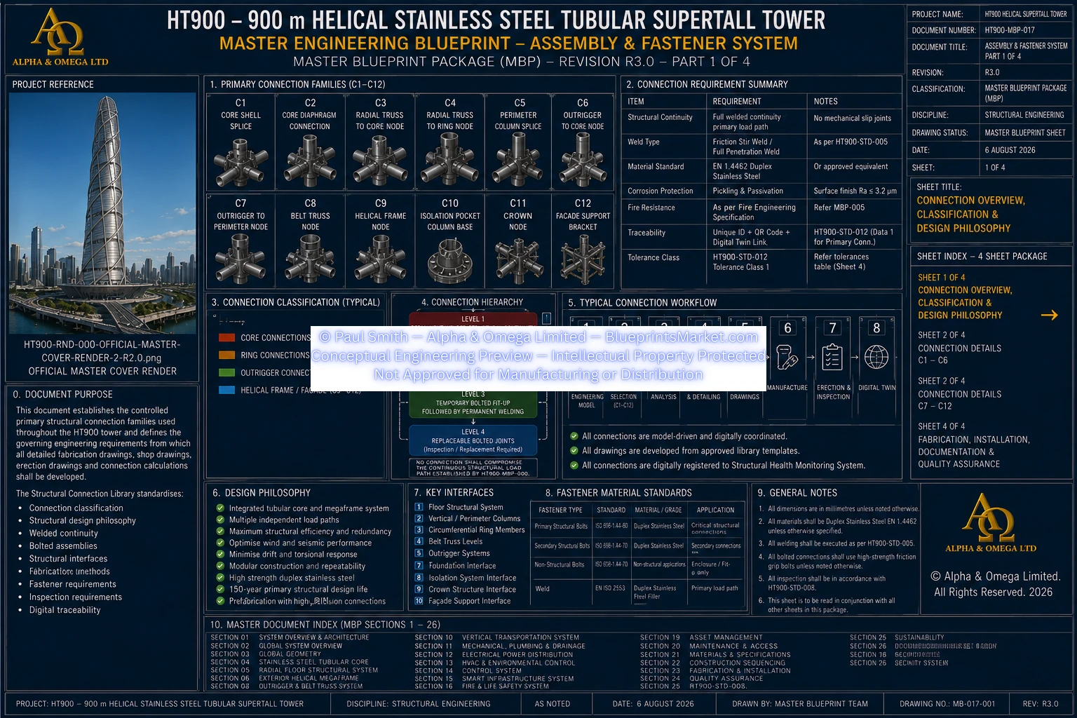
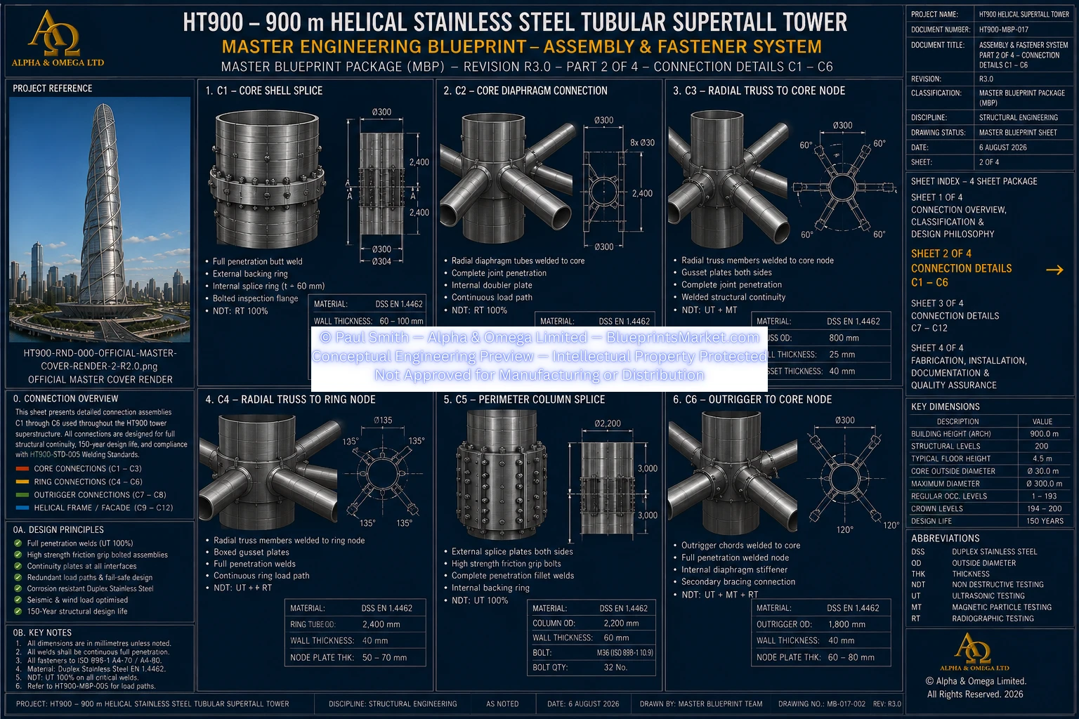
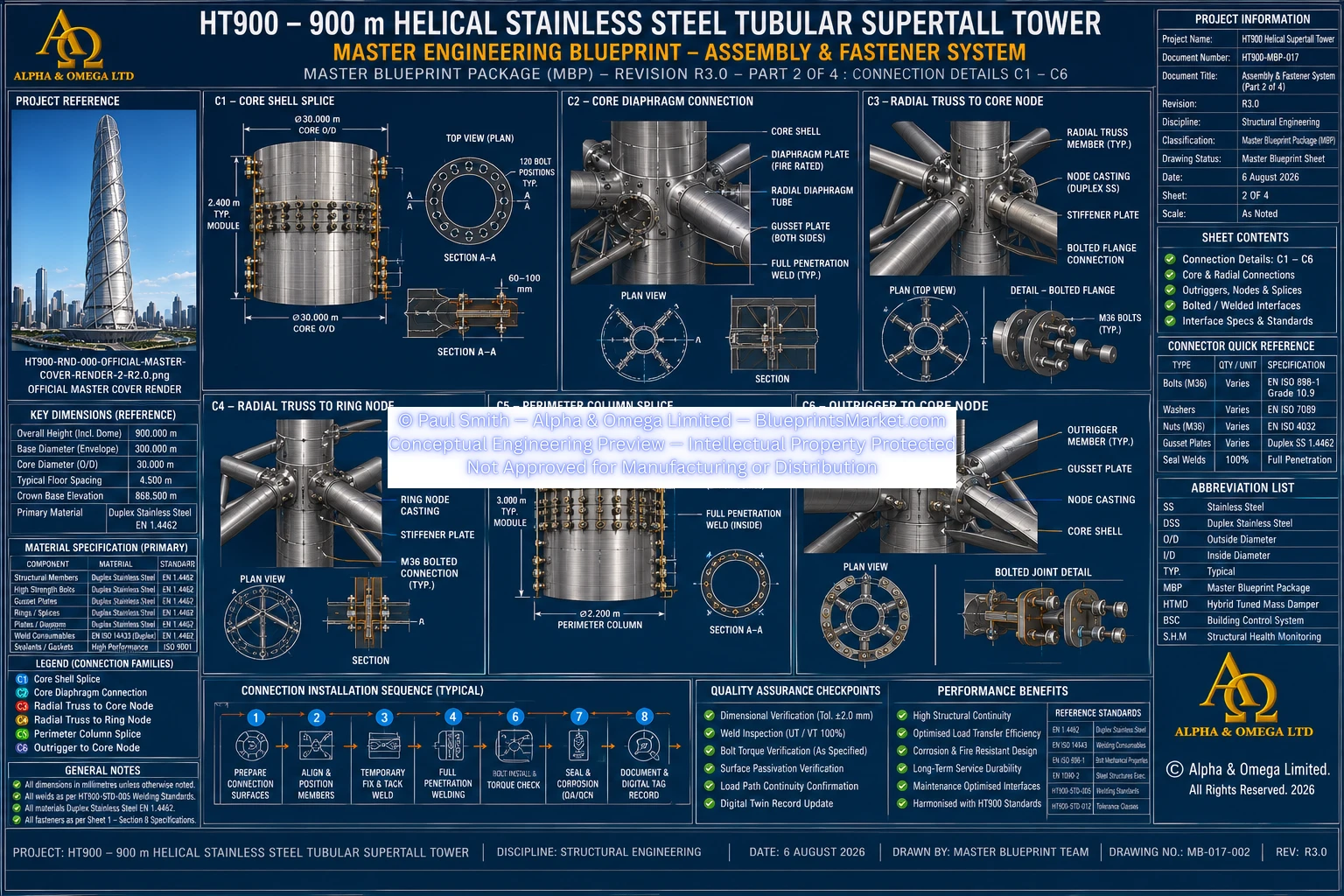
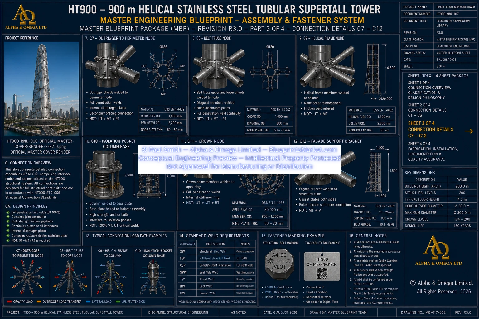
Permanent structural continuity within the HT900 system is achieved through a hybrid approach combining welded structural continuity and application-specific high-strength bolted connections.
Primary Connection Methods
- Full-penetration welded structural joints
- Factory-fabricated structural node assemblies
- Qualified high-strength stainless or Duplex structural bolts
- Temporary bolted fit-up during erection
- Permanent welded closure joints where required
- Replaceable bolted interfaces where future replacement is practical
Temporary erection bolts remain permanent only where specifically permitted by the applicable structural connection design.
7. Application-Based Fastener Classes
R3.0 does not use one universal fastener size for all structural connections. Fastener selection is based on the structural function of each connection.
| Secondary Framing | Preliminary range: M24–M36 |
|---|---|
| Primary Floor Nodes | Preliminary range: M36–M48 |
| Column Splices | Preliminary range: M48–M64 |
| Outrigger Nodes | Preliminary range: M64–M72 |
| Isolation Pocket Base Flange | 24 × M64 per support |
| Façade Support Brackets | A4-80 M10–M16 |
Final fastener sizing requires detailed structural calculations and project-specific connection engineering.
8. Structural Bolted Connection Classes
Class A — Temporary Erection Joints
- Module alignment
- Temporary fit-up
- Survey control
- Construction-stage stability
Class B — Preloaded Slip-Resistant Structural Joints
- Primary structural nodes
- Column splices
- Structural ring connections
- Belt-Truss connections
- Outrigger connections
Class C — Bearing-Type Structural Joints
- Secondary structural framing
- Replaceable structural interfaces
- Selected maintenance structures
Class D — Replaceable Maintenance Joints
- Mechanical equipment interfaces
- Maintenance platforms
- Replaceable architectural components
- Service supports
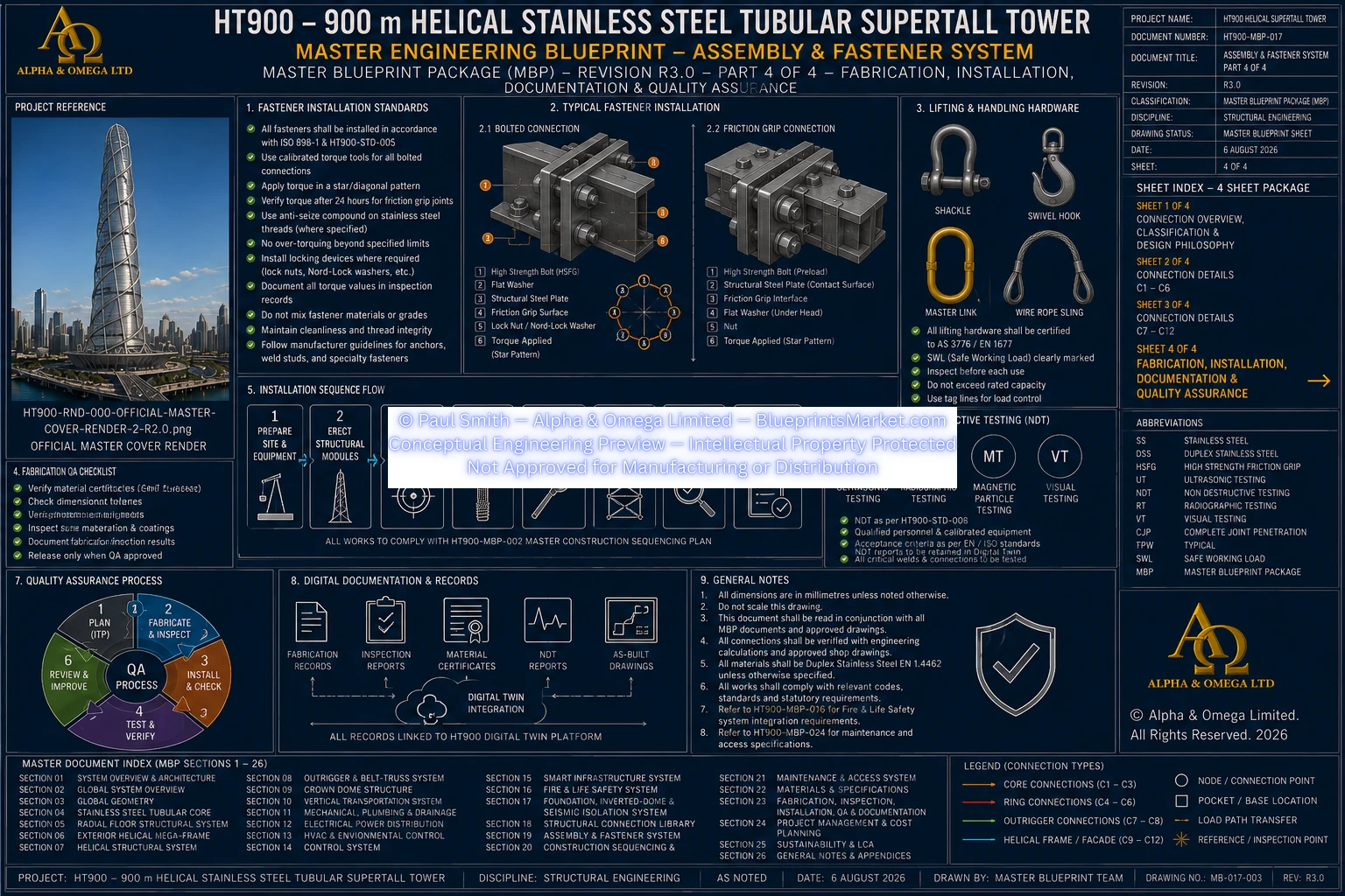
9. Fastener Installation & Preload Control
Large primary structural fasteners require controlled installation and documented preload verification.
Primary Installation Requirements
- Hydraulic bolt tensioning for primary M48 and larger structural bolts
- Controlled preload procedures
- Certified installation processes
- Permanent fastener identification
- Installation and inspection records
Preload Verification
- Direct-Tension Indicators where specified
- Ultrasonic preload verification where specified
- Recorded preload values
- Visual inspection
- Permanent installation records
Calibrated torque alone is not treated as the sole preload-control method for critical high-strength stainless structural bolts.
10. Washer, Nut & Material Compatibility
Permanent structural bolt assemblies use components selected for compatibility with Duplex and Super Duplex Stainless Steel structural systems.
Typical Components
- Hardened flat washers
- Qualified heavy hex nuts
- Approved locking systems
- Direct-Tension Indicators where specified
- Approved lubrication systems where required
Durability Objectives
- Minimise galling
- Minimise crevice corrosion
- Reduce chloride-related deterioration
- Prevent unisolated galvanic incompatibility
- Maintain long-term preload stability
Spring washers are not used within primary slip-resistant structural joints under the current R3.0 philosophy.
11. Structural Welding System
Qualified structural welding provides the primary means of permanent structural continuity throughout major HT900 load paths.
Primary Structural Welds
- Full-penetration groove welds
- Core structural splices
- Perimeter column splices
- Structural ring connections
- Outrigger nodes
- Belt-Truss nodes
- Crown structural nodes
Qualified Welding Processes
- GTAW — Gas Tungsten Arc Welding
- GMAW — Gas Metal Arc Welding
- SAW — Submerged Arc Welding
- FCAW where specifically qualified
Compatible Weld Materials
- ER2209 Duplex Stainless Steel filler
- Qualified equivalent Duplex fillers
- Approved Super Duplex fillers where applicable
Welding procedures require controlled heat input, qualified procedures and welders, inspection hold points and appropriate post-weld cleaning and passivation.
12. Controlled Factory Fabrication
The HT900 construction philosophy maximises factory fabrication before transport to site.
Typical Factory Operations
- CNC cutting
- CNC machining
- Precision forming
- Robotic welding where practical
- Trial assembly
- Laser dimensional survey
- Positive Material Identification
- Weld inspection
- Surface treatment
- Pickling and passivation
- Final acceptance testing
Factory Quality Control
- Material heat-number traceability
- Positive Material Identification
- Match marking
- Lift-point certification
- Structural-node inspection
- Temporary interface inspection
- Carbon-steel contamination prevention
- Digital coordinate capture
- Transport protection
13. Module Lifting System
Every transportable HT900 structural module incorporates engineered lifting provisions suited to its geometry, mass and centre of gravity.
Typical Lifting Provisions
- Certified lifting lugs
- Temporary lifting brackets
- Internal lifting frames where required
- Balanced lifting points
- Lift-identification marks
- Defined rigging interfaces
Lift Engineering Considerations
- Module centre of gravity
- Rigging configuration
- Dynamic lifting effects
- Crane capacity and lifting radius
- Wind operating limits
- Temporary structural stability
- Tagline control
- Lift simulation where required
- Controlled exclusion zones
Final lifting factors and operating limits are established by the applicable lifting code and project-specific lifting engineering.
14. Erection Alignment & Survey Control
Alignment of the 900 metre structural system is controlled through a coordinated project survey framework rather than one universal full-height tolerance.
Alignment Systems
- Laser survey equipment
- Permanent survey monuments
- Precision guide pins
- Adjustable shim systems
- Temporary alignment frames
- Digital survey recording
Primary Survey References
- Tower centreline as global origin
- Foundation diaphragm level as Z0
- 48-sector structural grid
- 7.5° primary angular spacing
- Helical phase control
- Temperature compensation
- Weld-shrinkage correction
- Construction-stage movement compensation
15. Structural Tolerance Philosophy
HT900 R3.0 does not apply one universal tolerance to every structural component.
Tolerances are assigned according to component type, fabrication process, erection stage and structural function.
Representative Factory Fabrication Tolerances
| Tube Outside Diameter | Typical ±2 mm |
|---|---|
| Plate Thickness | Typical ±1 mm |
| Machined Components | Typical ±1 mm |
| Structural Node Geometry | Typical ±2 mm |
| Bolt-Hole Position | Typical ±1 mm |
| Member Length | Typical ±3 mm |
Representative Erection Tolerances
| Module Alignment | Typical ±5 mm |
|---|---|
| Ring Alignment | Typical ±5 mm |
| Outrigger Alignment | Typical ±5 mm |
| Crown Module Alignment | Typical ±5 mm |
Overall building alignment is governed by continuous project survey verification throughout construction.
16. Quality Assurance & Inspection
Quality assurance is integrated throughout fabrication, transport, erection and final structural acceptance.
Material Verification
- Material certification review
- Positive Material Identification
- Heat-number verification
- Mechanical-property verification
- Surface inspection
- Dimensional inspection
Site Inspection
- Delivery and storage inspection
- Lift-preparation inspection
- Alignment verification
- Temporary connection inspection
- Permanent connection inspection
- Bolt preload verification
- Weld inspection
- Survey verification
- Final acceptance inspection
Non-Destructive Testing
- Visual Testing (VT)
- Ultrasonic Testing (UT)
- Phased Array Ultrasonic Testing (PAUT)
- Radiographic Testing where specified
- Dye Penetrant Testing
- Other compatible inspection methods where approved
17. Structural Identification & Lifecycle Traceability
Every structural module is intended to receive a permanent identification record before leaving the fabrication facility.
Module Records
- Module identification number
- Material certification records
- Fabrication records
- Inspection records
- Welding records
- Fastener records
- Transport records
- Installation records
- Maintenance records
Detailed digital asset architecture, system databases and implementation-level traceability requirements remain within the applicable HT900 technical documentation and subsequent project-specific engineering systems.
18. Stainless-Steel Corrosion Control
Long-term structural durability is supported through material selection, fabrication quality, surface treatment and controlled structural detailing.
Primary Durability Measures
- EN 1.4462 Duplex Stainless Steel where specified
- Super Duplex Stainless Steel where required
- Pickling
- Passivation
- Drainage detailing
- Crevice minimisation
- Surface cleaning
- Permanent inspection access
Construction Contamination Controls
- Carbon-steel contamination prevention
- Chloride contamination control
- Surface-damage prevention
- Heat-tint removal where required
- Controlled storage
- Prevention of standing-water accumulation
19. Typical Installation Sequence
- Survey verification
- Foundation construction
- Isolation foundation installation
- Stainless Steel Tubular Core erection
- Perimeter tubular column installation
- Radial floor-sector installation
- Concentric support-ring installation
- Helical structural-member installation
- Belt-Truss installation
- Outrigger installation
- Crown Dome installation
- Façade installation
- Mechanical-system installation
- Electrical-system installation
- Smart-infrastructure installation
- Fire & Life Safety installation
- Final testing and commissioning
Major construction stages require structural verification before progression to the next principal phase.
20. Structural Safety & Construction Control
- Engineered lifting plans
- Temporary-works certification
- Fall-protection systems
- Controlled exclusion zones
- Temporary structural-stability verification
- Crane and rigging coordination
- Welding and hot-work procedures
- Weather monitoring
- Survey hold points
- Structural inspection hold points
- Quality-assurance checkpoints
Temporary structural stability must be maintained throughout every stage of the erection process.
21. Inspection & Structural Acceptance
Structural assemblies undergo progressive inspection from factory fabrication through transport, erection and final commissioning.
Factory Acceptance
- Material certification verification
- Positive Material Identification
- Dimensional inspection
- Structural-node inspection
- Weld inspection
- Non-Destructive Testing where specified
- Surface-treatment verification
- Trial-assembly verification
- Lifting-point certification
Site Acceptance
- Survey verification
- Module-alignment inspection
- Structural-connection inspection
- Bolt-preload verification
- Weld inspection
- Structural-movement verification
- Temporary-works removal inspection
- Final dimensional survey
22. Maintenance & Design-Life Philosophy
The HT900 assembly philosophy incorporates long-term inspection accessibility and maintainability throughout the intended structural lifecycle.
Permanent Maintenance Provisions
- Structural inspection galleries
- Internal maintenance corridors
- Permanent access platforms
- Crown maintenance systems
- Foundation inspection access
- Certified lifting points
- Replaceable equipment interfaces
- Structural Health Monitoring access
| Primary Structural Design Life | 150 years |
|---|---|
| Permanent Welded Structure | 150-year design objective |
| Duplex Stainless Structural Members | 150-year design objective |
| Replaceable Mechanical Components | Scheduled lifecycle replacement |
| Replaceable Structural Fasteners | Inspectable and replaceable where applicable |
23. System Integration
The Assembly & Fastener System is coordinated with the principal HT900 structural and construction systems.
- Stainless Steel Tubular Core
- Radial Floor Structural System
- Exterior Tubular Megaframe
- Helical Structural System
- Outrigger & Belt-Truss System
- Crown Dome Structure
- Foundation & Isolation System
- Structural Connection Library
- Construction Sequencing
- Maintenance & Access Systems
- Master Engineering Specifications
24. Engineering Logic Summary
- Controlled factory fabrication maximises quality and repeatability before modules reach the construction site.
- 13.5 metre three-floor erection cycles provide a repeatable structural assembly sequence.
- Application-specific structural bolts are used instead of a single universal fastener specification.
- Full-penetration structural welding establishes permanent continuity through major primary load paths.
- Survey-controlled erection manages alignment, helical phase and cumulative dimensional variation.
- Inspection and Non-Destructive Testing provide progressive verification throughout fabrication and erection.
- Corrosion-control and maintenance provisions support the long-term structural design-life objective.
25. Professional Engineering Notice
The HT900 Assembly & Fastener System forms part of the HT900 R3.0 conceptual Master Blueprint Package.
Information presented on this public page summarises the principal assembly philosophy, modular erection strategy, connection classes, fastener hierarchy, welding philosophy, lifting concepts, fabrication controls, inspection principles and lifecycle maintenance strategy.
Detailed bolt schedules, complete connection geometry, preload values, fabrication procedures, welding procedures, lifting calculations, tolerance schedules, inspection plans, quantities and component-specific assembly instructions remain within the applicable HT900 technical documentation or require subsequent project-specific professional engineering.
Any real-world fabrication, erection or construction requires complete structural calculations, connection engineering, fabrication drawings, shop drawings, erection drawings, qualified welding procedures, project lifting plans, temporary-works engineering, inspection and test plans, regulatory approval and certification by appropriately qualified and licensed engineering professionals.
HT900-MBP-018 — ASSEMBLY & FASTENER SYSTEM
Copyright — Alpha & Omega Limited
All blueprint files, CAD parameters, architectural concepts, engineering specifications, and written content are the exclusive intellectual property of Alpha & Omega Limited. No part of the Stainless‑Steel Skyscraper Blueprint Package may be reproduced, distributed, or adapted without written consent.
Licensing, Copyright & Patent Restrictions
This engineering system and all associated blueprint materials, CAD files, diagrams, schematics, dimensional tables, and technical narratives are licensed, not sold, and remain the exclusive intellectual property of Alpha & Omega Limited.
This product is not eligible for patenting by any purchaser, user, organization, or third party. Patent filings, provisional patents, utility models, derivative patents, reverse‑engineering for patent purposes, and intellectual property claims are strictly prohibited.
Redistribution, resale, sublicensing, public posting, dataset inclusion, or any form of unauthorized duplication of blueprint materials, CAD files, diagrams, or engineering concepts is strictly prohibited. No license tier grants ownership, patent rights, or rights to file for intellectual property protection.
All architectural & engineering systems are conceptual and require full professional engineering validation before any real‑world use, construction, prototyping, or structural implementation.
Full legal details are available in the Terms & Conditions .