
Full Bill of Materials & Engineering Specification Set
HT900 — Integrated Materials, Asset Classification, Traceability & Lifecycle Engineering System
1.0 Master Bill of Materials Overview
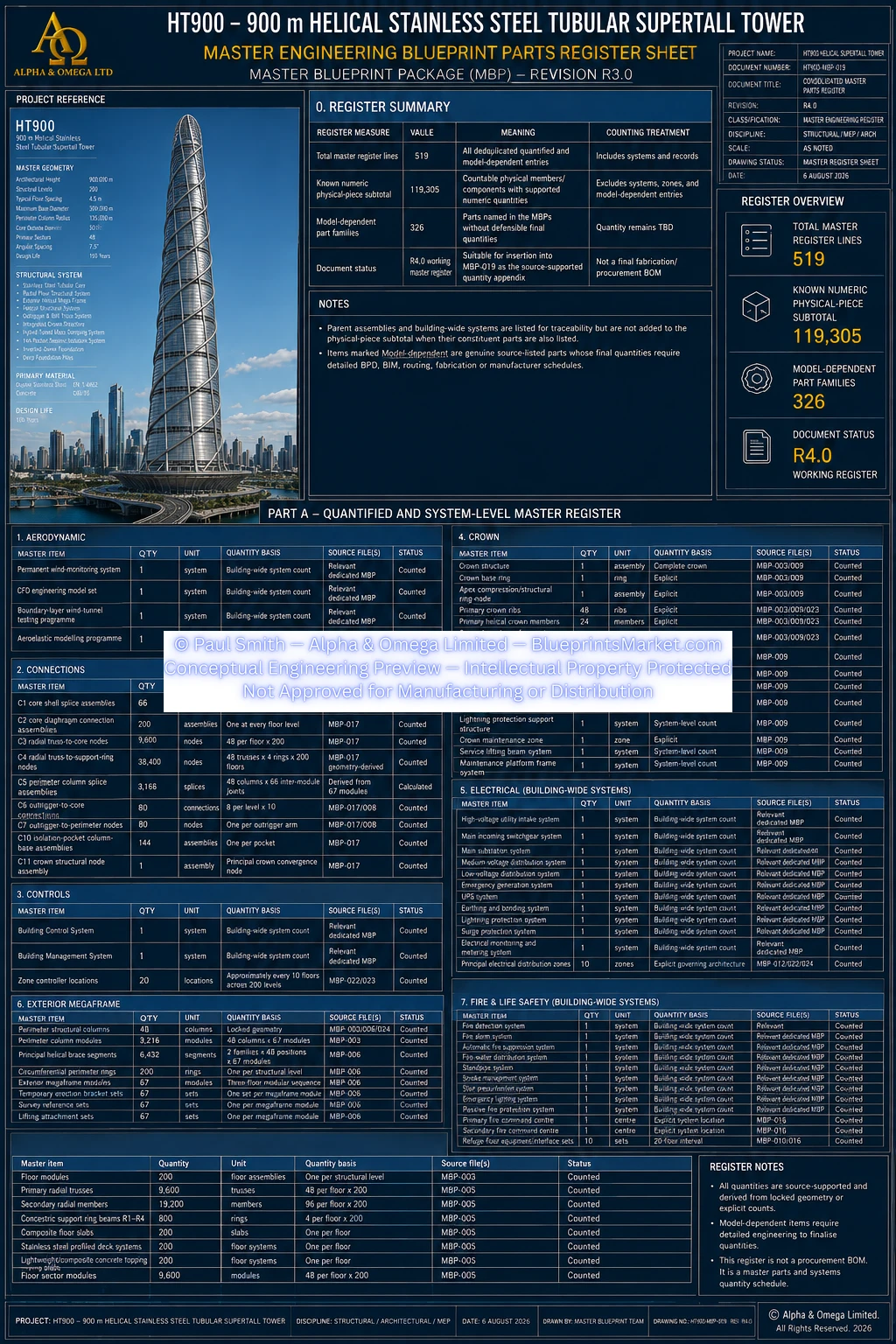
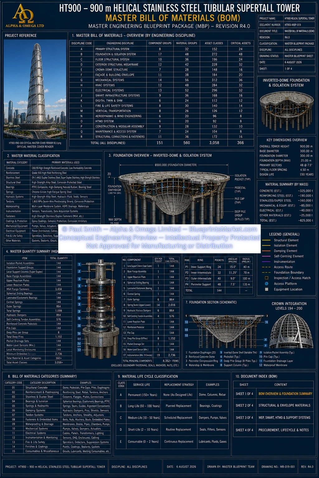
The HT900 Master Bill of Materials provides the coordinated engineering framework for classifying the permanent, replaceable and temporary assets associated with the 900-metre Helical Stainless-Steel Tubular Supertall Tower.
It is considerably more than a conventional purchasing list. The system connects materials, assemblies, equipment, engineering disciplines, inspection records, lifecycle information and Digital Twin asset records within one coordinated engineering structure.
Final procurement quantities are not represented as universally fixed values where those quantities depend upon coordinated BIM modelling, structural analysis, manufacturer selection, fabrication detailing or project-specific engineering.
2.0 Governing Project Baseline
| Architectural Height | 900 m |
|---|---|
| Structural Levels | 200 |
| Typical Structural Level Height | 4.5 m |
| Maximum Base Envelope Diameter | 300 m |
| Foundation Diameter | 300 m |
| Tubular Structural Core Diameter | 30 m |
| Primary Structural Grid | 48 sectors |
| Primary Angular Grid | 7.5° |
| Seismic Isolation Pockets | 144 |
| Deep Foundation Piles | 1,152 |
| Primary Structural Design Life | 150 years |
3.0 Engineering BOM Philosophy
Every controlled HT900 material, component and assembly is treated as an engineering asset rather than simply a purchasing item.
Asset records within the complete engineering package are organised around information such as:
- Part and assembly identification
- Engineering discipline and system classification
- Revision status
- Material specification
- Manufacturing and inspection status
- Installation and commissioning status
- BIM and Digital Twin identification
- Maintenance and inspection history
- Replacement strategy
- Lifecycle condition records
This allows material and equipment records to remain traceable throughout design, construction, commissioning, operation, maintenance and eventual replacement.
4.0 Master Engineering Classification
The HT900 Bill of Materials is organised across the complete multidisciplinary building system.
Primary Structural System
Tubular core, perimeter megaframe, helical framing, structural rings, nodes and major load-bearing assemblies.
Foundation & Isolation
Inverted-dome foundation, isolation support systems, deep foundation and associated permanent substructure.
Floor Structural System
Radial structural sectors, ring systems, secondary framing and composite floor construction.
Exterior Megaframe
Perimeter columns, helical structural members, structural nodes and exterior load-transfer interfaces.
Crown Structure
Upper structural framing, crown interfaces, access systems and integrated equipment supports.
Façade & Building Envelope
Stainless-steel cladding, curtain-wall systems, secondary façade framing, insulation, weather-control systems and support interfaces.
Mechanical Systems
Water, drainage, pumping and associated mechanical infrastructure and replaceable equipment.
HVAC Systems
Environmental control, ventilation, air distribution and associated plant systems.
Electrical Systems
Power distribution, emergency systems, electrical infrastructure and equipment.
Smart Infrastructure
Building controls, communications, sensing networks and intelligent infrastructure.
Digital Twin
Asset identification, lifecycle records, inspection history and engineering configuration data.
Fire & Life Safety
Detection, suppression, smoke management, emergency systems and protected life-safety infrastructure.
Vertical Transportation
Passenger, service, freight and firefighter transportation systems and associated infrastructure.
Maintenance & Access
Permanent inspection access, Building Maintenance Units and lifecycle servicing systems.
Connections & Fasteners
Controlled structural connection families, permanent joining systems and associated hardware.
Construction Systems
Temporary lifting, transport, erection, survey and modular assembly infrastructure.
5.0 Master Material Philosophy
Material classification follows the coordinated HT900 engineering baseline and preserves the tower's tubular stainless-steel structural architecture.
| Primary Structural System | Duplex Stainless Steel EN 1.4462 |
|---|---|
| Foundation & Isolation | Reinforced Concrete, Duplex Stainless Steel and selected Super Duplex Stainless Steel |
| Floor Structural System | Duplex Stainless Steel with Composite Floor Construction |
| Exterior Structural Megaframe | Duplex Stainless Steel EN 1.4462 |
| Crown Structural System | Duplex Stainless Steel |
| Façade & Building Envelope | Stainless Steel, Aluminium and Architectural Glass Systems |
| Mechanical Systems | Stainless Steel, Copper, HDPE, EPDM and system-specific engineering materials |
| Smart Infrastructure | Fibre Optics, Electronics and Protected Equipment Enclosures |
| Fire & Life Safety | Certified Fire-Protection Materials and Systems |
Reinforced concrete is not used as the primary HT900 structural core. The governing structural core and principal above-foundation framing remain tubular stainless steel.
6.0 Primary Structural BOM Scope
The Master BOM covers the permanent primary structural system of the tower, including:
- Stainless-steel tubular core assemblies
- Core shell and diaphragm systems
- 48 perimeter megacolumns
- Exterior helical structural framing
- Structural ring systems
- Radial floor structural framing
- Outrigger structures
- Belt-truss systems
- Crown framing
- Primary structural nodes
- Permanent structural connections
- Inspection and maintenance interfaces
Detailed member dimensions, structural connection schedules, fabrication data and procurement quantities remain within the licensed engineering package.
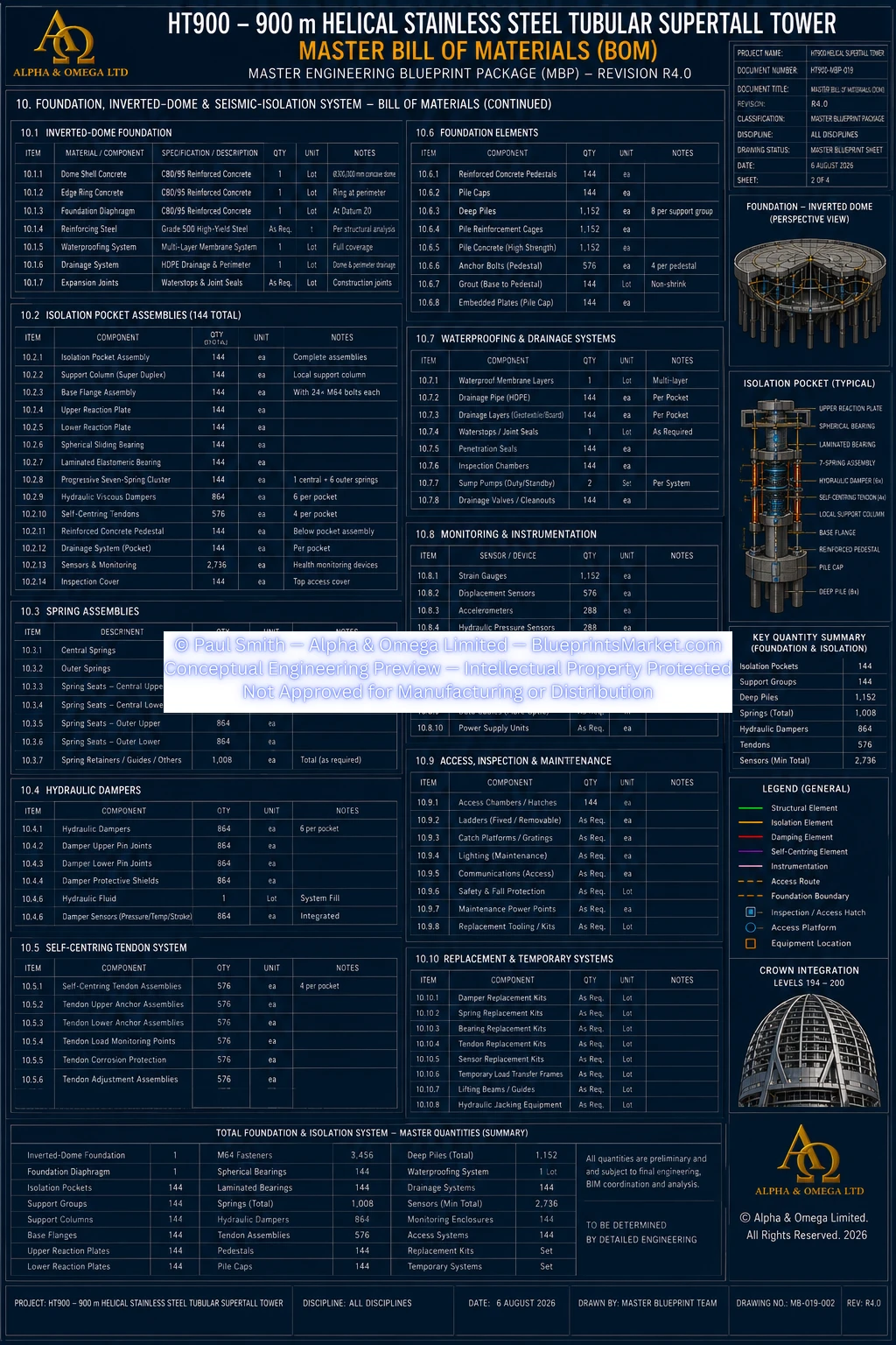
7.0 Foundation & Seismic-Isolation BOM Scope
The foundation BOM is coordinated around the current 300-metre inverted-dome foundation baseline.
Public Baseline
- 1 complete inverted-dome foundation system
- 1 reinforced foundation diaphragm
- 144 seismic-isolation pocket assemblies
- 144 foundation support groups
- 144 local isolation-support interfaces
- 144 pile-cap groups
- 1,152 total deep piles
- Complete foundation waterproofing
- Complete drainage infrastructure
- Structural-health monitoring interfaces
- Inspection and component-replacement provisions
Detailed bearing specifications, spring schedules, damper characteristics, tendon data, reinforcement, fastener quantities and component geometry are retained within the licensed Master Blueprint Package.
8.0 Radial Floor Structural BOM
The floor-system BOM follows the current 48-sector radial structural architecture rather than the superseded concept of a single transportable floor assembly.
Each structural floor is coordinated around:
- 48 radial structural sectors
- Primary radial tubular framing
- Concentric structural ring systems
- Secondary stainless-steel framing
- Composite floor construction
- Architectural floor systems
- Service support systems
- Inspection and access interfaces
9.0 Exterior Cladding & Curtain-Wall BOM
The Master BOM now includes the complete HT900 Exterior Cladding & Curtain Wall System as a dedicated building-envelope engineering category.
The façade is a secondary, maintainable and replaceable envelope system connected to the exterior tubular stainless-steel megaframe.
It does not replace or interrupt the primary structural load path formed by the tubular core, perimeter megacolumns, helical structural members, radial framing, outriggers, belt trusses and crown structure.
Façade BOM Categories
- Architectural stainless-steel cladding
- Unitised curtain-wall glazing
- Secondary façade framing
- Façade support interfaces
- Pressure-equalised rainscreen systems
- Thermal insulation
- Air and water-control systems
- Weather seals and gaskets
- Fire and cavity barriers
- Crown façade systems
- Maintenance and access interfaces
- Lightning and monitoring interfaces
Final opaque-panel counts, glazed-unit counts, support-bracket quantities, façade fasteners and final façade mass remain dependent upon the coordinated architectural and engineering model.
10.0 Mechanical, HVAC & Electrical BOM
Building-services assets are classified separately from the permanent structural framework and include both permanent infrastructure and equipment intended for planned replacement.
Mechanical
- Water systems
- Pumping systems
- Drainage systems
- Valves and control devices
- Mechanical equipment
HVAC
- Air-distribution infrastructure
- Environmental-control plant
- Ventilation equipment
- Ductwork systems
- Control interfaces
Electrical
- Power-distribution infrastructure
- Emergency power
- Transformers
- Switchboards
- UPS systems
- Lighting systems
- Monitoring and metering
11.0 Fire & Life Safety BOM
Fire and life-safety assets are independently classified within the Master BOM.
Categories include:
- Fire detection
- Fire alarm infrastructure
- Automatic suppression
- Fire-water systems
- Smoke-control infrastructure
- Pressurisation equipment
- Emergency communications
- Emergency lighting
- Refuge-floor equipment
- Fire Command Centre systems
12.0 Smart Infrastructure & Digital Twin
Digital asset identification is integrated into the HT900 Bill of Materials architecture.
Smart Infrastructure categories include:
- Fibre-optic communications backbone
- Network infrastructure
- Industrial control hardware
- Structural monitoring sensors
- Environmental sensors
- Vibration and displacement monitoring
- Energy monitoring
- Digital Twin computing infrastructure
- Engineering workstations and data systems
13.0 Vertical Transportation BOM
Vertical-transportation systems maintain their own independent equipment and lifecycle asset records.
The BOM includes categories for:
- Passenger elevators
- Express elevator systems
- Service and freight elevators
- Firefighter elevators
- Guide systems
- Motors and drives
- Doors and landing equipment
- Control systems
- Emergency communications
14.0 Dynamic & Aerodynamic Systems
The Master BOM also coordinates the specialist systems associated with tower motion, aerodynamic monitoring and vibration control.
Hybrid Tuned Mass Damper System
- Primary damping mass
- Support structure
- Actuation and damping systems
- Bearings and guide systems
- Sensors
- Controllers
- Hydraulic infrastructure
- Maintenance systems
Aerodynamic & Wind Monitoring
- Wind instrumentation
- Pressure monitoring
- Weather stations
- Façade-pressure monitoring
- Data-acquisition infrastructure
15.0 Maintenance & Access BOM
Maintenance equipment and permanent access infrastructure form dedicated BOM categories.
Permanent Infrastructure
- Maintenance platforms
- Catwalks and walkways
- Permanent safety systems
- Inspection platforms
- Equipment access floors
- Permanent lifting interfaces
Replaceable Access Equipment
- Building Maintenance Units
- Inspection equipment
- Suspended work platforms
- Rescue equipment
- Certified lifting and rigging equipment
16.0 Permanent & Replaceable Asset Classification
The HT900 distinguishes permanent infrastructure from assets intended for periodic replacement.
Permanent Infrastructure
- Tubular stainless-steel structural core
- Exterior structural megaframe
- Radial floor framing
- Structural ring systems
- Outriggers and belt trusses
- Crown structural framing
- Primary structural nodes
- Permanent foundations
- Permanent structural support systems
Planned Replaceable Assets
- Bearings
- Damping equipment
- Selected isolation components
- Pumps and valves
- Mechanical plant
- Electrical equipment
- Control equipment
- Sensors and electronics
- Façade glazing and seals
- Building Maintenance Units
Replacement intervals are based on condition, inspection history, manufacturer recommendations, operating performance and lifecycle engineering.
17.0 Digital Asset Traceability
Controlled components can maintain a permanent Digital Twin engineering identity linking the physical asset to its engineering and lifecycle records.
Lifecycle records may include:
- Procurement records
- Manufacturing history
- Material certification
- Transport records
- Installation records
- Commissioning reports
- Inspection history
- Maintenance history
- Repairs and modifications
- Condition assessments
- Replacement history
18.0 Quality Assurance & Inspection
Quality assurance forms part of the BOM system rather than being maintained as an unrelated project record.
Inspection and quality records may include:
- Material certification
- Dimensional inspection
- Welding inspection
- Surface and passivation inspection
- Non-destructive examination
- Pressure testing
- Electrical testing
- Functional testing
- Installation verification
- Commissioning verification
19.0 Procurement Philosophy
The HT900 Master Bill of Materials establishes procurement governance rather than presenting unverified purchasing totals.
Final procurement schedules would be generated from the fully coordinated engineering model using:
- Approved structural calculations
- Coordinated BIM models
- Approved fabrication drawings
- Equipment schedules
- Final manufacturer selections
- Mechanical and hydraulic calculations
- Electrical load studies
- HVAC engineering
- Approved structural connection designs
This prevents preliminary planning values from being incorrectly represented as final procurement quantities.
20.0 Multidisciplinary Engineering Coordination
The Master BOM acts as a central coordination layer linking the major HT900 engineering disciplines.
- Primary Structural System
- Foundation & Seismic Isolation
- Radial Floor System
- Exterior Helical Megaframe
- Façade & Curtain Wall
- Mechanical Systems
- HVAC
- Electrical Distribution
- Fire & Life Safety
- Vertical Transportation
- Smart Infrastructure
- Structural Health Monitoring
- Hybrid Tuned Mass Damping
- Aerodynamic Engineering
- Construction Sequencing
- Maintenance & Access
- Digital Twin & Lifecycle Management
A change to one engineering discipline therefore requires coordinated review of affected assets across the BOM system.
21.0 Engineering Summary
The HT900 Master Bill of Materials provides the central material, asset and lifecycle classification system for the complete 900-metre tubular stainless-steel skyscraper concept.
It preserves the governing 30-metre tubular stainless-steel structural core, 48-sector primary structural grid, 300-metre foundation envelope, 144 seismic-isolation assemblies and 1,152-pile deep-foundation baseline while coordinating the tower's structural, architectural, façade, mechanical, electrical, life-safety, transportation and digital systems.
Rather than treating the BOM as a static list of assumed quantities, the current system treats it as a controlled engineering asset database supporting procurement, fabrication, inspection, commissioning, operations, maintenance and future lifecycle replacement.
22.0 Licensed Engineering Documentation
This public page presents the scope and engineering philosophy of the HT900 Master Bill of Materials.
The licensed HT900 Master Blueprint Package contains the detailed conceptual engineering BOM documentation, including controlled material classifications, component schedules, system breakdowns, foundation and isolation component data, façade engineering schedules, connection information, engineering traceability requirements and associated blueprint documentation.
Exact procurement quantities, fabrication dimensions, member schedules, connection details, fastener schedules, welding data and other implementation-level technical specifications are intentionally not reproduced on this public overview page.
Final real-world procurement or construction quantities would require coordinated project-specific BIM modelling, engineering analysis, detailed design, manufacturer selection, regulatory review and certification by appropriately qualified engineering professionals.
HT900-MBP-019 — FULL BILL OF MATERIALS & SPECIFICATION SET
Copyright — Alpha & Omega Limited
All blueprint files, CAD parameters, architectural concepts, engineering specifications, and written content are the exclusive intellectual property of Alpha & Omega Limited. No part of the Stainless‑Steel Skyscraper Blueprint Package may be reproduced, distributed, or adapted without written consent.
Licensing, Copyright & Patent Restrictions
This engineering system and all associated blueprint materials, CAD files, diagrams, schematics, dimensional tables, and technical narratives are licensed, not sold, and remain the exclusive intellectual property of Alpha & Omega Limited.
This product is not eligible for patenting by any purchaser, user, organization, or third party. Patent filings, provisional patents, utility models, derivative patents, reverse‑engineering for patent purposes, and intellectual property claims are strictly prohibited.
Redistribution, resale, sublicensing, public posting, dataset inclusion, or any form of unauthorized duplication of blueprint materials, CAD files, diagrams, or engineering concepts is strictly prohibited. No license tier grants ownership, patent rights, or rights to file for intellectual property protection.
All architectural & engineering systems are conceptual and require full professional engineering validation before any real‑world use, construction, prototyping, or structural implementation.
Full legal details are available in the Terms & Conditions .