
1. Construction Sequencing & Assembly Methodology Overview
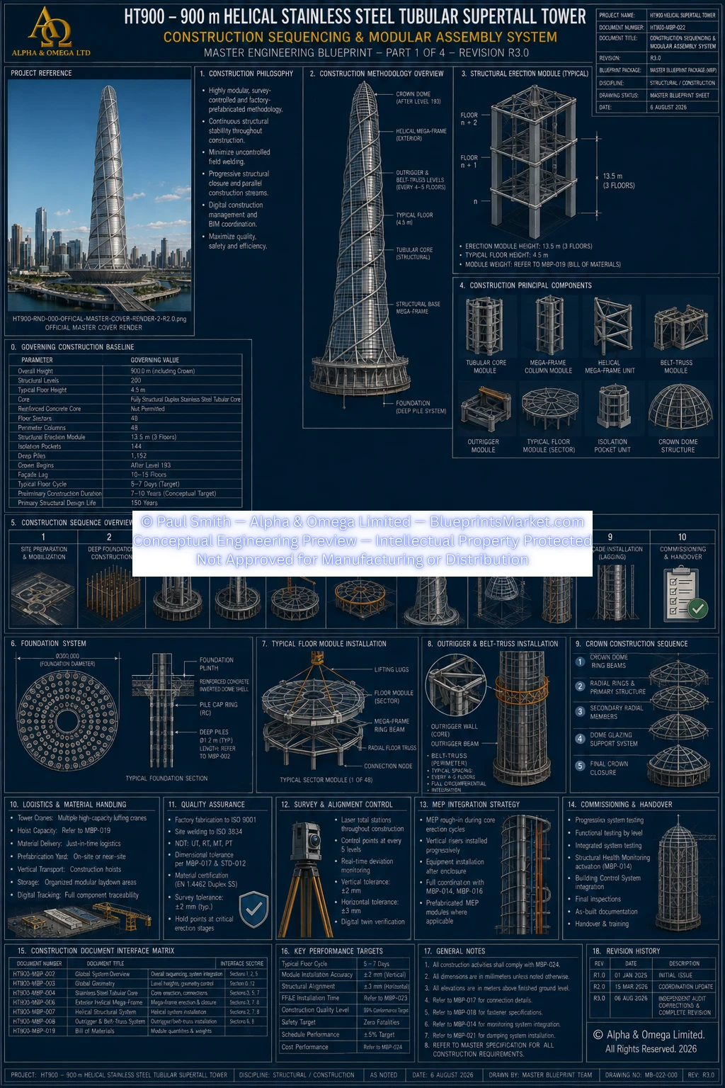
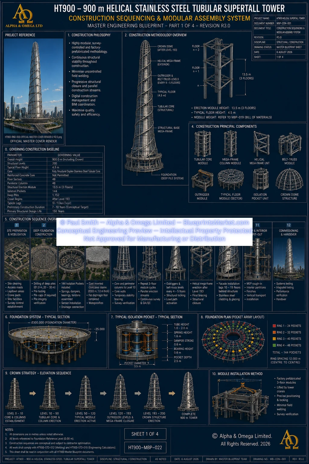
The HT900 construction methodology is based on a coordinated, modular erection strategy developed specifically for the 900 metre Helical Stainless-Steel Tubular Supertall Tower.
Construction progresses from site investigation and deep-foundation works through the inverted-dome foundation, seismic-isolation system, stainless-steel structural base, tubular core, perimeter megaframe, radial floor systems, helical structural systems, outriggers, belt trusses, building services, façade, Crown Dome and final integrated commissioning.
The strategy prioritises:
- Controlled modular fabrication
- Balanced structural erection
- Continuous survey verification
- Temporary structural stability
- Permanent structural continuity
- Progressive quality assurance
- Non-Destructive Testing
- Structural Health Monitoring integration
- Digital construction records
- Lifecycle traceability
2. Locked Construction Baseline
Before physical construction or fabrication release, the principal HT900 geometry and structural interfaces are frozen against the governing project baseline.
| Architectural Height | 900.0 metres |
|---|---|
| Structural Levels | 200 |
| Typical Floor Spacing | 4.5 metres |
| Typical Structural Erection Module | 13.5 metres / 3 floors |
| Maximum Base Diameter | 300.0 metres |
| Tubular Structural Core Outside Diameter | 30.0 metres |
| Primary Structural Sectors | 48 |
| Primary Sector Spacing | 7.5° |
| Total Helical Rotation | 160° |
| Primary Structural Material | Duplex Stainless Steel EN 1.4462 |
| Primary Structural Design-Life Objective | 150 years |
The central tower core is a full tubular Duplex Stainless-Steel structural core. A reinforced-concrete structural tower core is not part of the HT900 superstructure.
3. Pre-Construction Engineering & Project Controls
Construction begins with design freeze, coordinate control, system-interface verification and establishment of the permanent engineering control network.
Principal Pre-Construction Activities
- Topographical survey
- Geotechnical investigation
- Groundwater investigation
- Seismic site characterisation
- Environmental assessment
- Utility identification and diversion planning
- Heavy-haul and construction access planning
- Temporary drainage and dewatering planning
- Crane and lifting-zone planning
- Material laydown planning
- Protected stainless-steel storage planning
- Permanent survey-reference establishment
Core geometry, radial sectors, floor elevations, helical geometry, foundation interfaces, isolation pockets, vertical transportation, services, outriggers, belt trusses, Crown Dome and major structural connections are coordinated before fabrication release.
4. Foundation Excavation & Groundworks
Excavation is undertaken for the full approximately 300 metre diameter inverted-dome foundation and associated isolation and deep-foundation infrastructure.
Principal Groundworks
- Staged excavation
- Groundwater control
- Temporary drainage
- Excavation support where required
- Inverted-dome formation
- Isolation-pocket excavations
- Pile working platforms
- Temporary construction access
- Foundation drainage infrastructure
- Waterproofing preparation
| Foundation Diameter | Approximately 300 metres |
|---|---|
| Maximum Inverted-Dome Depth | Approximately 25 metres |
5. Deep Foundation Construction
The deep foundation system is constructed and verified before tower superstructure erection begins.
Typical Deep-Foundation Sequence
- Digital setting-out of pile locations
- Trial and test piling where required
- Production pile boring
- Bore inspection
- Reinforcement-cage installation
- High-strength concrete placement
- Pile-integrity verification
- Specified pile-load testing
- Pile-head trimming
- Completed pile survey
- Pile-cap construction
- Integration with the overlying foundation structure
Tower steel erection does not proceed until the required foundation acceptance and structural-strength criteria are achieved.
6. Inverted-Dome Foundation Construction
The reinforced-concrete inverted-dome foundation forms the principal below-ground load-distribution system beneath the isolated tower.
Principal Construction Sequence
- Prepare the final formation
- Install foundation drainage
- Install waterproofing
- Install structural reinforcement
- Install embedded structural interfaces
- Integrate isolation-pocket interfaces
- Integrate pile-cap interfaces
- Form the inverted-dome geometry
- Place concrete in controlled construction sectors
- Manage thermal and shrinkage effects
- Cure the foundation structure
- Survey the completed geometry
- Inspect waterproofing interfaces
- Complete structural acceptance
7. Foundation Diaphragm & Structural Interface
A reinforced-concrete foundation diaphragm is constructed above the inverted-dome system to form the principal horizontal structural interface beneath the isolated superstructure.
Integrated Elements
- Radial structural ribs
- Circular structural rings
- Isolation-pocket openings
- Local support zones
- Tubular-core interfaces
- Perimeter megaframe interfaces
- Drainage systems
- Waterproofing
- Inspection access
- Monitoring infrastructure
- Embedded structural anchorage
8. 144-Pocket Seismic-Isolation Array Construction
The seismic-isolation system is constructed as an integral part of the foundation rather than installed later as an independent secondary system.
| Isolation Ring 1 | 24 pockets |
|---|---|
| Isolation Ring 2 | 32 pockets |
| Isolation Ring 3 | 40 pockets |
| Isolation Ring 4 | 48 pockets |
| Total Isolation Pockets | 144 |
Principal Isolation-System Components
- Reinforced-concrete isolation pockets
- Stainless-steel support interfaces
- Laminated elastomeric bearings
- Spherical/sliding bearing systems
- Progressive spring assemblies
- Hydraulic damping systems
- Self-centering systems
- Drainage
- Waterproofing
- Inspection access
- Structural monitoring instrumentation
9. Isolation-System Preload & Initial Commissioning
Before superstructure loading begins, the complete isolation system is inspected, surveyed, instrumented and commissioned.
Initial Verification
- Dimensional inspection
- Bearing inspection
- Spring inspection
- Damper inspection
- Self-centering system inspection
- Anchorage verification
- Drainage testing
- Waterproofing inspection
- Sensor calibration
- Zero-load displacement recording
- Baseline vibration monitoring
- Structural Health Monitoring communication verification
This establishes the initial structural-health reference state before tower erection begins.
10. Structural Base Megaframe Erection
Above the isolated foundation, the stainless-steel structural base creates the transition into the principal HT900 superstructure.
Principal Base Components
- Isolation support interfaces
- Structural base plates
- Base structural ring
- Perimeter column starters
- Tubular-core starter structure
- Radial base framing
- Circumferential structural members
- Temporary stability systems
Structural connections follow the controlled HT900 connection methodology rather than being independently redesigned or improvised during field erection.
11. 30 Metre Tubular Stainless-Steel Core Erection
The central structural core is erected from prefabricated Duplex Stainless-Steel tubular structural assemblies.
It is not constructed using reinforced-concrete slipform or jump-form construction.
| Core Outside Diameter | 30.0 metres |
|---|---|
| Typical Core Erection Module | 13.5 metres |
| Levels per Typical Module | 3 |
Typical Core-Module Sequence
- Lift prefabricated core sections
- Position to survey control
- Install temporary restraint
- Connect the lower structural interface
- Install ring diaphragms
- Install internal structural stiffening
- Complete structural connections
- Complete specified welding
- Complete required bolting and preload
- Perform Non-Destructive Testing
- Complete dimensional survey
- Release the module for subsequent construction
12. Perimeter Megacolumn Erection
The perimeter tubular megacolumn system is erected progressively in coordination with the central tubular core.
| Primary Structural Sectors | 48 |
|---|---|
| Angular Spacing | 7.5° |
Erection proceeds in balanced sectors around the tower to minimise excessive temporary eccentric loading.
Typical Erection Activities
- Megacolumn segment lifting
- Survey-controlled alignment
- Temporary bracing
- Ring-member connections
- Radial structural connections
- Permanent welding
- High-strength bolting
- Non-Destructive Testing
- Survey verification
- Structural monitoring baseline update
13. Radial Floor Structural System Installation
Floor construction progresses sector-by-sector between the tubular core and exterior megaframe.
Principal Floor-System Elements
- Primary radial structural members
- Circumferential and concentric ring members
- Secondary stainless-steel framing
- Structural deck
- Composite slab construction
- Diaphragm connections
- MEP penetrations
- Vertical transportation openings
- Service-riser openings
- Façade interfaces
Each structural level follows the controlled 48-sector floor geometry.
14. Typical 13.5 Metre / Three-Floor Erection Cycle
The principal repetitive superstructure sequence is organised around a coordinated three-floor construction module.
Floor n → Floor n+1 → Floor n+2 = one 13.5 metre structural erection cycle.
Typical Cycle
- Install tubular-core module
- Install perimeter megacolumn module
- Install primary structural ring members
- Install radial floor structure
- Install floor-sector modules
- Install secondary structural framing
- Maintain temporary structural stability
- Complete permanent structural connections
- Extend service risers
- Extend vertical transportation infrastructure
- Install façade-support interfaces
- Extend Structural Health Monitoring
- Complete dimensional survey
- Complete required NDT
- Issue quality release
The following 13.5 metre erection module proceeds only after the preceding cycle has achieved the required structural, dimensional and inspection acceptance.
15. Exterior Helical Megaframe Erection
The exterior helical structural system is installed progressively with the rising tower rather than added later as architectural cladding.
The helical system is a primary structural component and develops the controlled 160° total tower rotation.
Principal Interfaces
- Perimeter megacolumns
- Floor structural rings
- Radial floor framing
- Outrigger systems
- Belt-Truss systems
- Crown Dome Structure
- Façade-support structure
- Primary structural nodes
Helical members are installed in balanced sectors to maintain temporary structural stability throughout erection.
16. Outrigger & Belt-Truss Construction
The Outrigger & Belt-Truss System is installed progressively as the rising tower reaches the designated structural transfer levels.
Principal Outrigger Levels
Main outrigger zones occur at approximately twenty-level intervals through the tower structure.
Typical Outrigger Installation Sequence
- Prepare tubular-core connection nodes
- Install local structural reinforcement
- Prepare perimeter structural nodes
- Lift prefabricated outrigger assemblies
- Install temporary support
- Connect to the tubular core
- Connect to the perimeter megaframe
- Complete structural plates and stiffeners
- Complete high-strength bolting where required
- Complete specified permanent welding
- Perform critical NDT
- Verify structural geometry
- Transfer structural load progressively
- Remove temporary supports after acceptance
Circumferential Belt-Truss systems are installed at principal outrigger levels and at intermediate structural levels as required by the HT900 structural architecture.
17. Structural Connections, Welding, Fasteners & NDT
Structural connections are based on the controlled HT900 connection-family system and are predominantly prefabricated under controlled factory conditions.
Construction Control Principles
- Controlled factory fabrication
- Precision CNC cutting and machining
- Qualified welding procedures
- Qualified welders
- High-strength structural fasteners where required
- Controlled bolt preload and verification
- Dimensional inspection
- Non-Destructive Testing
- Material traceability
- Connection identification
- Permanent inspection records
Detailed weld geometry, fastener schedules, preload requirements and connection dimensions remain within the applicable HT900 technical documentation and subsequent project-specific construction engineering.
18. Vertical Transportation & Core Services Installation
Vertical transportation and core-service infrastructure are installed progressively as the Stainless Steel Tubular Core rises.
Progressively Installed Systems
- Passenger elevator infrastructure
- Service elevator infrastructure
- Firefighter and emergency elevator infrastructure
- Protected emergency stairs
- Mechanical risers
- Electrical risers
- Water and drainage risers
- Smoke-exhaust shafts
- Communications risers
- Maintenance corridors
Sensitive final equipment is installed after the applicable shaft and building zones are sufficiently enclosed and controlled.
19. MEP, Fire & Life-Safety Installation
Mechanical, electrical, plumbing, drainage, communications, control and fire/life-safety infrastructure progresses in parallel with structural construction wherever practical.
Progressive Systems Integration
- Mechanical distribution
- Electrical distribution
- Water systems
- Drainage
- Communications infrastructure
- Building controls
- Fire detection
- Fire suppression
- Smoke-management systems
- Emergency power and communications
- Refuge-floor infrastructure
- Firefighter operational systems
Life-safety infrastructure is installed progressively rather than deferred until the end of the project.
20. Façade, Cladding & Weather-Envelope Installation
Façade installation progresses from structurally released areas while the tower continues upward.
Principal Envelope Activities
- Façade-support bracket installation
- Stainless-steel architectural cladding
- Glazing and infill systems
- Weather membranes
- Seals and flashings
- Drainage paths
- Movement joints
- Façade fire stopping
- Progressive water-tightness testing
- Progressive air-tightness testing
The envelope is coordinated with structural movement, thermal movement, seismic-isolation displacement and the tower's helical aerodynamic geometry.
21. Structural Health Monitoring During Construction
Structural Health Monitoring is extended progressively as the building rises.
Construction Monitoring Concepts
- Foundation movement monitoring
- Isolation-pocket monitoring
- Core deformation monitoring
- Megaframe movement monitoring
- Structural acceleration monitoring
- Displacement monitoring
- Critical connection monitoring
- Environmental monitoring
- HTMD monitoring
- Digital construction records
Major structural construction stages establish successive baseline condition records for comparison throughout the remainder of the project and subsequent operational life.
22. Hybrid Tuned Mass Damper Installation
The Hybrid Tuned Mass Damping System is installed within the upper structural zone after its dedicated structural support interfaces have been completed and surveyed.
Principal Installation Stages
- Construct upper support structure
- Survey structural interfaces
- Install primary damping-system components
- Install damping and tuning systems
- Install monitoring sensors
- Install control and power infrastructure
- Complete maintenance and access provisions
- Commission passive operating mode
- Commission active control mode
- Integrate with BMS and Structural Health Monitoring
Final tuning is performed against the measured as-built dynamic properties of the completed tower.
23. Crown Dome Construction — Levels 194–200
Normal tower erection continues through Level 193 before transitioning into the integrated Crown Dome Structure.
| Crown Levels | 194–200 |
|---|---|
| Approximate Crown Base Elevation | 868.5 metres |
| Architectural Apex | 900.0 metres |
Principal Crown Construction
- Install crown base ring
- Connect crown to tubular core and perimeter structure
- Install primary crown ribs
- Install secondary structural members
- Install circumferential crown rings
- Complete apex structural closure
- Install crown floor diaphragms
- Install equipment and maintenance platforms
- Install permanent maintenance access
- Install crown communications and MEP systems
- Install lightning-protection infrastructure
- Install BMU and external maintenance systems
- Complete crown envelope closure
The Crown Dome is a structural continuation of the tower rather than an ornamental element attached after structural completion.
24. Continuous QA, Survey & Inspection
Quality assurance is maintained throughout the entire construction sequence rather than being treated only as a final commissioning task.
Principal Verification Activities
- Material certification
- Visual Testing
- Liquid Penetrant Testing where applicable
- Ultrasonic Testing
- Radiographic Testing where required
- Fastener preload verification
- Dimensional inspection
- Weld-profile inspection
- Corrosion-control inspection
- Structural survey
- Connection acceptance
- Progressive quality-release hold points
Continuous Geometric Control
- Tubular core
- Perimeter columns
- Floor structural rings
- Helical structural members
- Outrigger nodes
- Belt-Truss geometry
- Façade supports
- Crown structure
- Isolation-system movement
25. Integrated Testing & Final Commissioning
After major construction is complete, the tower enters a coordinated integrated testing and commissioning programme.
Principal Commissioning Systems
- Seismic-isolation system recommissioning
- Hybrid Tuned Mass Damper tuning
- Structural Health Monitoring baseline
- Fire and life-safety testing
- Smoke-control testing
- Emergency-power testing
- Vertical transportation commissioning
- Mechanical systems commissioning
- Electrical systems commissioning
- Water and drainage commissioning
- Façade performance testing
- Building Management System integration
- Communications testing
- Maintenance-system verification
The seismic-isolation system is reassessed under the substantially completed building dead load and compared with its original zero-load reference state.
26. Final Handover & Lifecycle Transition
Construction handover includes final structural acceptance, commissioning records, maintenance-access verification, operational training and establishment of the completed-building monitoring baseline.
Handover Framework
- Final structural inspection
- Final dimensional acceptance
- Structural Health Monitoring baseline
- Isolation-system acceptance
- HTMD acceptance
- Façade acceptance
- MEP commissioning records
- Fire and life-safety acceptance
- Vertical transportation certification
- Maintenance-access verification
- Operating procedures
- Maintenance procedures
- Inspection schedules
- Emergency procedures
- Operator training
Permanent access to major structural, foundation, isolation, building-service, damping and maintenance systems is verified as part of the handover process.
27. Completed Structural Construction Path
At final structural handover, the completed load-resisting system extends continuously from the crown and occupied tower levels through the foundation and into the ground.
Crown / façade / occupied floors → floor diaphragms and radial structural system → Exterior Helical Megaframe + perimeter megacolumns ↔ Belt Trusses & Outriggers ↔ 30 metre Tubular Duplex Stainless-Steel Core → structural base megaframe → 144 seismic-isolation pockets → inverted-dome foundation → pile caps → deep-pile foundation → competent ground.
28. Construction Engineering Logic Summary
- Construction begins with a locked global geometry and controlled project datum.
- The deep foundation, inverted-dome foundation and 144-pocket isolation system are completed and verified before major superstructure loading.
- The 30 metre tubular Duplex Stainless-Steel Core and perimeter megaframe rise together rather than as independent structures.
- The typical superstructure progresses through a 13.5 metre / three-floor repeating erection cycle.
- The 48-sector radial floor system and 160° helical megaframe are erected progressively as part of the primary structure.
- Outriggers and Belt Trusses are integrated at their designated structural levels as the tower rises.
- MEP, vertical transportation, fire/life safety, façade-support and monitoring infrastructure are installed progressively rather than being deferred until structural top-out.
- Continuous survey, NDT, structural inspection and quality-release hold points govern progression between major construction stages.
- The Crown Dome, HTMD, communications, maintenance and lightning-protection systems complete the upper tower.
- Final integrated testing establishes the tower's operational structural and monitoring baseline before occupancy.
29. Professional Engineering Notice
The HT900 Construction Sequencing & Assembly Methodology forms part of the HT900 conceptual Master Blueprint and Construction Sequence framework.
This public page summarises the overall construction philosophy, principal sequencing stages, modular erection concept, structural integration strategy, progressive building-services installation, inspection philosophy and commissioning framework.
Detailed lift plans, crane selection, rigging calculations, temporary-works engineering, fabrication sequences, weld procedures, fastener installation schedules, detailed construction tolerances, temporary bracing calculations, logistics planning, construction programme durations, workforce requirements and implementation-level construction instructions require subsequent project-specific professional engineering.
The information presented here is not a construction method statement, fabrication instruction, temporary-works design or construction-ready engineering package.
Any real-world implementation requires complete site-specific construction engineering, geotechnical verification, temporary-works design, lifting engineering, contractor planning, structural analysis, approved construction drawings, inspection and test plans, regulatory approvals and supervision by appropriately qualified and licensed engineering professionals.
HT900-MBP-022 — CONSTRUCTION SEQUENCING & ASSEMBLY METHODOLOGY
Copyright — Alpha & Omega Limited
All blueprint files, CAD parameters, architectural concepts, engineering specifications, and written content are the exclusive intellectual property of Alpha & Omega Limited. No part of the Stainless‑Steel Skyscraper Blueprint Package may be reproduced, distributed, or adapted without written consent.
Licensing, Copyright & Patent Restrictions
This engineering system and all associated blueprint materials, CAD files, diagrams, schematics, dimensional tables, and technical narratives are licensed, not sold, and remain the exclusive intellectual property of Alpha & Omega Limited.
This product is not eligible for patenting by any purchaser, user, organization, or third party. Patent filings, provisional patents, utility models, derivative patents, reverse‑engineering for patent purposes, and intellectual property claims are strictly prohibited.
Redistribution, resale, sublicensing, public posting, dataset inclusion, or any form of unauthorized duplication of blueprint materials, CAD files, diagrams, or engineering concepts is strictly prohibited. No license tier grants ownership, patent rights, or rights to file for intellectual property protection.
All architectural & engineering systems are conceptual and require full professional engineering validation before any real‑world use, construction, prototyping, or structural implementation.
Full legal details are available in the Terms & Conditions .