
Vertical Transportation Systems
HT900 — Core-Integrated Passenger, Service, Firefighter & Emergency Vertical Circulation System
1.0 System Overview
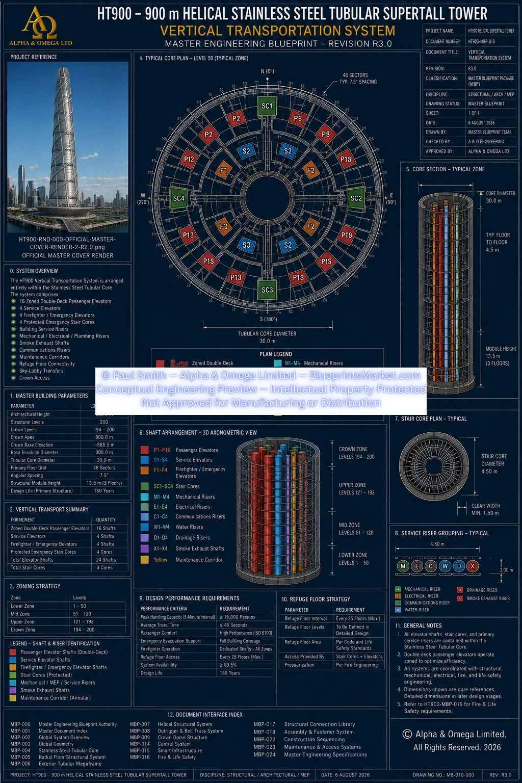
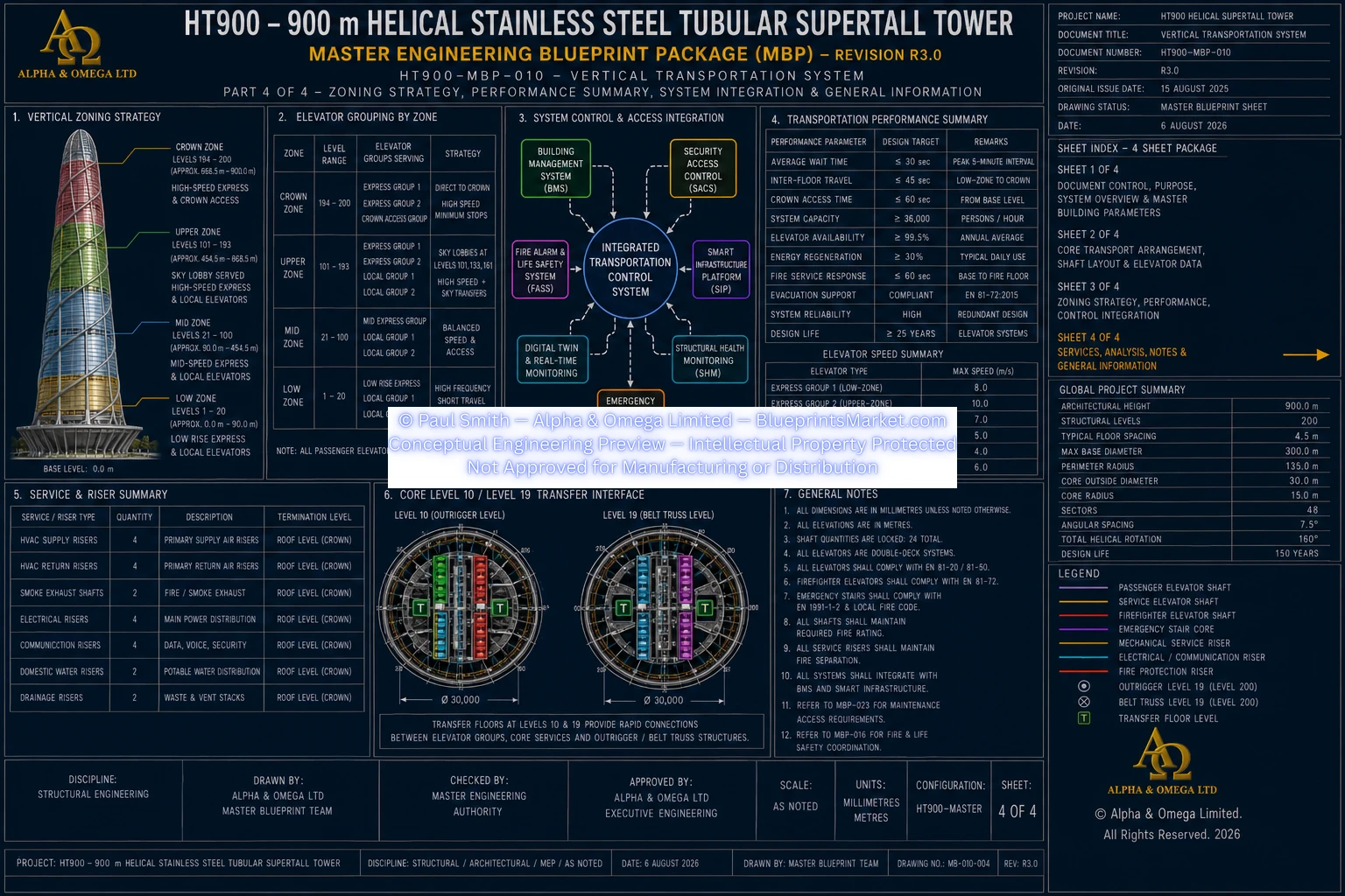
The HT900 Vertical Transportation System provides the principal passenger, service, logistics, emergency-response and maintenance circulation network for the 900-metre Helical Stainless-Steel Tubular Supertall Tower.
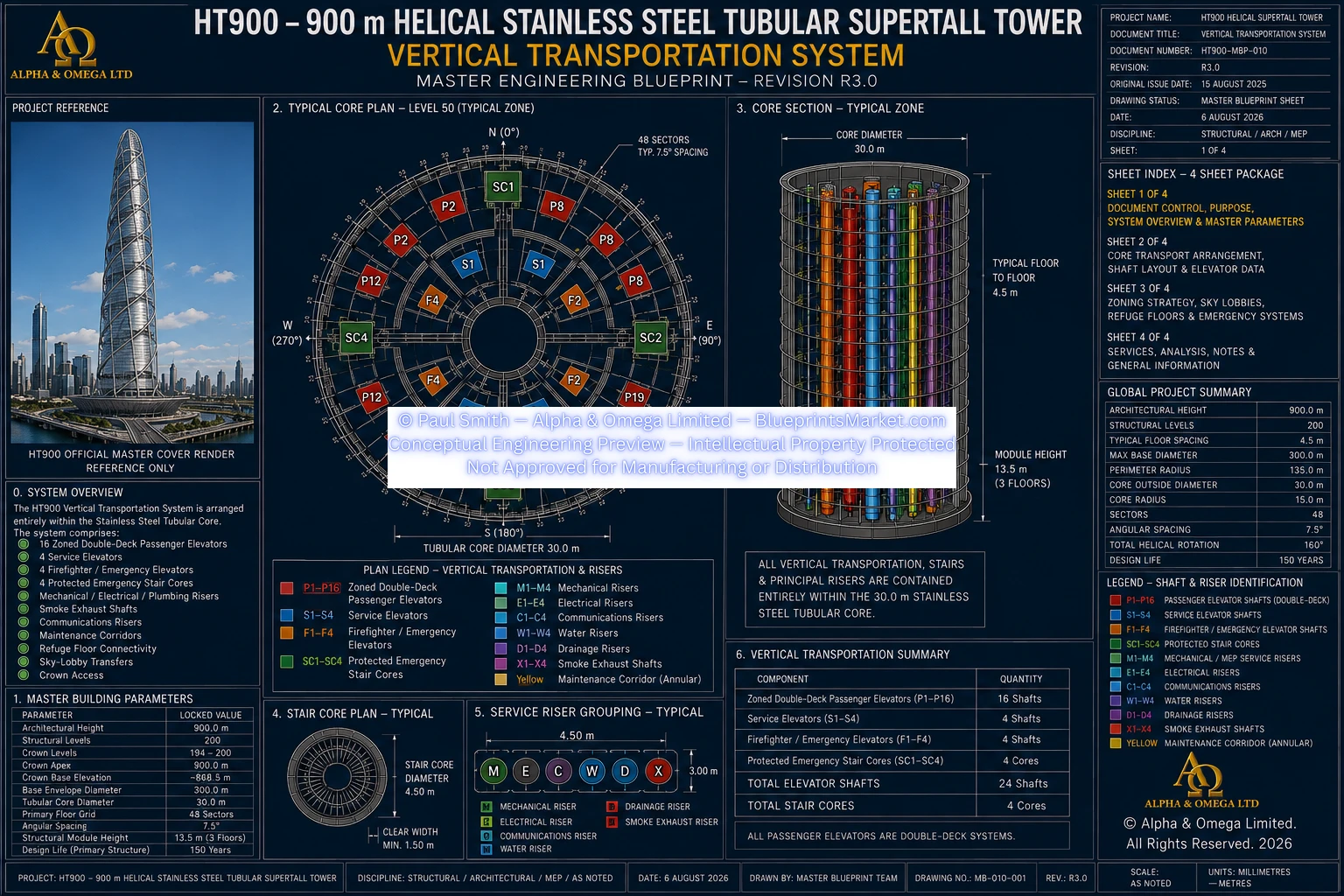
The entire principal vertical transportation system is integrated within the building's 30-metre-diameter Duplex Stainless-Steel Tubular Core.
All principal elevator shafts, all protected emergency stair cores and the major vertical service risers are contained inside the stainless-steel structural core.
The surrounding occupied floors and exterior structure follow the tower's helical geometry while the central transportation core maintains the coordinated vertical circulation, service and life-safety infrastructure.
There is no reinforced-concrete primary structural core.
2.0 Governing Building Baseline
| Architectural Height | 900 m |
|---|---|
| Structural Levels | 200 |
| Regular Occupied Levels | Levels 1–193 |
| Integrated Crown | Levels 194–200 |
| Crown Base Elevation | Approximately 868.5 m |
| Crown Apex | 900 m |
| Maximum Base Envelope Diameter | 300 m |
| Structural Core Diameter | 30 m |
| Primary Floor Grid | 48 sectors |
| Primary Structural Design Life | 150 years |
3.0 Core-Integrated Transportation Architecture
Vertical transportation is concentrated within the stainless-steel tubular core so that passenger, service and emergency movement remains coordinated with the tower's principal vertical structural spine.
Principal Core Transportation Systems
- 16 zoned double-deck passenger elevator shafts
- 4 dedicated service elevator shafts
- 4 dedicated firefighter / emergency elevator shafts
- 4 protected emergency stair cores
Associated Core Service Infrastructure
- HVAC supply risers
- HVAC return risers
- Smoke-exhaust shafts
- Electrical risers
- Communications risers
- Fire-protection risers
- Domestic-water risers
- Drainage risers
- Protected maintenance corridors
Horizontal passenger circulation and horizontal service distribution transfer outward from the core at the relevant structural levels.
4.0 Principal Elevator Shaft Matrix
| Passenger Elevator Shafts | 16 |
|---|---|
| Passenger Configuration | Zoned Double-Deck |
| Service Elevator Shafts | 4 |
| Firefighter / Emergency Elevator Shafts | 4 |
| Total Principal Elevator Shafts | 24 |
| Protected Emergency Stair Cores | 4 |
| Primary Location | Inside the Stainless-Steel Tubular Core |
Express or shuttle operation is accommodated within the controlled passenger-shaft arrangement rather than by adding an independent uncoordinated shaft group.
5.0 Passenger Transportation Zoning
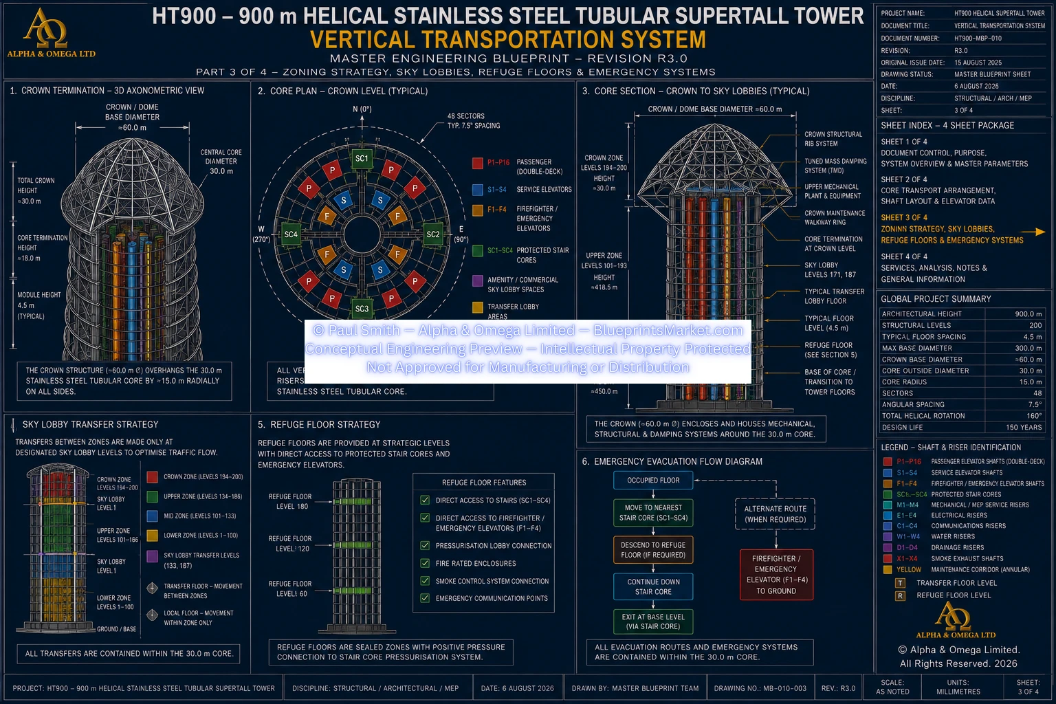
Passenger movement is divided into three principal vertical zones to reduce unnecessary full-height travel and improve operational efficiency.
| Low Zone | Ground to approximately 300 m |
|---|---|
| Middle Zone | Approximately 300–600 m |
| High Zone | Approximately 600–868.5 m |
| Crown Connection | Upper occupied levels to Crown facilities |
Crown transportation provides access to appropriate upper-level operational, observation, communications, maintenance and structural-service areas.
6.0 Passenger Elevator Speed Strategy
Elevator speed varies according to the transportation zone rather than applying one universal speed throughout the tower.
| Low Zone | Approximately 8–10 m/s |
|---|---|
| Middle Zone | Approximately 10–14 m/s |
| High Zone | Approximately 14–18 m/s |
Final operating speeds, acceleration, jerk, ride-quality limits and car characteristics are subject to manufacturer selection, traffic modelling and certification.
7.0 Double-Deck Passenger Elevator System
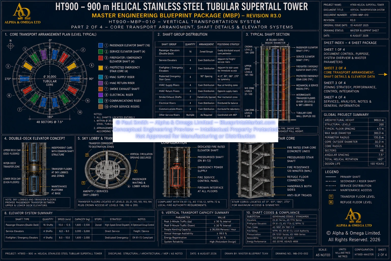
The primary passenger system uses 16 zoned double-deck passenger elevator shafts located within the Tubular Stainless-Steel Core.
Primary Functions
- High-capacity passenger movement
- Zoned tower circulation
- Sky-lobby transfers
- Peak-period traffic management
- Inter-zone passenger transfers
- Crown connectivity
- Accessible transportation
Control Functions
- Destination dispatch
- Intelligent group control
- Passenger-flow balancing
- Peak-period management
- Energy optimisation
- Maintenance diagnostics
- Predictive maintenance
- Digital Twin integration
Final elevator-car dimensions and rated loads remain manufacturer-dependent and are not represented as locked universal values on this public page.
8.0 Sky-Lobby & Transfer Strategy
Major passenger-transfer zones are coordinated with the tower's structural, mechanical and life-safety architecture.
Principal transfer areas occur conceptually near:
- Approximately 300 m
- Approximately 600 m
- Approximately 810–850 m
These transfer zones may coordinate with:
- Sky lobbies
- Refuge floors
- Mechanical distribution zones
- Outrigger levels
- Belt-truss levels
- Structural Health Monitoring systems
- Service and maintenance facilities
9.0 Service Elevator System
Four dedicated service elevator shafts are located inside the Stainless-Steel Tubular Core.
These elevators support:
- Building operations
- Equipment transport
- Maintenance activities
- Plant replacement
- Waste handling
- Mechanical-level access
- Refuge-floor access
- Crown maintenance
- Construction and logistics functions
Service-elevator capacity, speed and equipment selection remain subject to detailed logistics analysis and manufacturer coordination.
10.0 Firefighter & Emergency Elevator System
The HT900 incorporates four dedicated firefighter / emergency elevator shafts, all contained within the protected Stainless-Steel Tubular Core.
Their principal functions include:
- Firefighter access
- Emergency-response movement
- Emergency evacuation support
- Rescue operations
- Medical emergency transport
- Fire-command access
- Maintenance emergency response
Life-Safety Features
- Protected shaft construction
- Fire-rated lobbies
- Independent emergency power
- Redundant communications
- Smoke protection
- Fire-command integration
- Drainage provisions
- Emergency recall
- Seismic operating logic
- Wind operating logic
11.0 Protected Emergency Stair System
The HT900 incorporates four permanently protected emergency stair cores.
All four stair systems are contained inside the 30-metre Stainless-Steel Tubular Core.
They remain vertically coordinated within the central core rather than following the helical rotation of the exterior tower envelope.
Primary Stair Functions
- Protected emergency evacuation
- Firefighter circulation
- Refuge-floor connectivity
- Emergency access between levels
- Redundant vertical escape routes
Stair-System Features
- Protected fire-rated enclosures
- Positive-pressure smoke protection
- Automatic pressure regulation
- Redundant pressurisation equipment
- Emergency power
- Emergency lighting
- Emergency communications
- Firefighter access
- Refuge-floor access
12.0 Refuge-Floor Connectivity
Protected refuge floors are distributed through the tower and form an important part of the vertical transportation and life-safety strategy.
The current conceptual baseline places refuge floors at approximately 20-floor intervals, equivalent to approximately 90 metres vertically.
Refuge floors connect with:
- Four protected emergency stairs
- Four firefighter / emergency elevators
- Service elevators
- Passenger elevators
- Protected circulation corridors
Final refuge-floor area and occupant capacity require project-specific occupant-load and fire-engineering analysis.
13.0 Elevator Machinery & Equipment Strategy
The transportation system may use conventional machine rooms, distributed machinery spaces or machine-room-less technologies, depending upon final elevator-manufacturer selection.
Equipment zones may be coordinated with:
- Base plant areas
- 300 m transfer zone
- 600 m transfer zone
- 810–850 m upper transfer zone
- Crown interface
Typical equipment may include traction machines, drive systems, controllers, braking equipment, communications hardware, monitoring systems and emergency-power interfaces.
Specific motor powers, sheave dimensions, suspension technology and equipment-room configurations remain manufacturer-dependent.
14.0 Elevator Shaft Engineering
Elevator shafts are integrated with the internal structural architecture of the Duplex Stainless-Steel Tubular Core.
Shaft systems incorporate:
- Independent guide-rail support framing
- Fire-rated shaft enclosures
- Fire-rated landing doors
- Maintenance clearances
- Drainage provisions
- Equipment-access provisions
- Structural-movement allowances
Guide systems must accommodate thermal movement, structural shortening, wind-induced sway, seismic movement and construction tolerances without compromising passenger safety or ride quality.
15.0 Structural Integration With the Stainless-Steel Core
Operational elevator loads are transferred directly into the Stainless-Steel Tubular Core.
Guide-rail and shaft-support systems interface with:
- Core shell structure
- Core ring diaphragms
- Internal core stiffeners
- Dedicated transportation-support framing
The transportation system remains structurally independent from the principal radial floor framing and the exterior structural megaframe.
Operational elevator loads are therefore not intentionally transferred into:
- Primary radial floor trusses
- Four concentric support rings
- Exterior Helical Megaframe
- Helical Structural System
- Curtain-wall framing
16.0 Structural Movement Accommodation
A 900-metre tower experiences measurable movement due to wind, thermal effects, structural shortening and seismic response.
The vertical transportation system therefore accommodates:
- Wind-induced building movement
- Thermal expansion and contraction
- Long-term structural shortening
- Seismic movement
- Construction-stage movement
- Local alignment tolerances
Flexible guide-support systems and intelligent operating logic are used rather than assuming unrealistic full-height shaft alignment tolerances.
17.0 Intelligent Transportation Control
The Vertical Transportation System interfaces with the HT900 Control System and Smart Infrastructure architecture.
Passenger & Operational Functions
- Destination dispatch
- Intelligent group control
- Traffic optimisation
- Passenger allocation
- Sky-lobby transfer coordination
- Peak-period traffic management
- Energy optimisation
- Maintenance diagnostics
- Predictive maintenance
Emergency Functions
- Fire recall
- Firefighter operation
- Emergency evacuation support
- Wind operating mode
- Seismic operating mode
- Emergency communications
18.0 Building-System Integration
Transportation controls receive coordinated information from multiple building systems.
- Destination-dispatch terminals
- Elevator-position systems
- Door-monitoring systems
- Passenger-loading sensors
- Structural Health Monitoring
- Wind-monitoring systems
- Fire-alarm network
- Building Management System
- Emergency-power systems
- Maintenance diagnostics
- Digital Twin
19.0 Electrical Power & Emergency Supply
Vertical transportation operates from the tower's redundant electrical infrastructure.
Normal Supply
- Redundant building electrical supplies
- Dedicated transportation distribution
- Equipment-specific power distribution
Emergency Supply
- Standby generation
- Emergency switchboards
- Protected emergency feeders
- Automatic transfer systems
- UPS-supported critical controls
Emergency power prioritises firefighter and emergency transportation, control systems, communications, shaft lighting and associated life-safety functions.
20.0 Elevator Safety Systems
The Vertical Transportation System incorporates multiple independent safety functions.
- Overspeed protection
- Redundant braking
- Emergency stopping systems
- Suspension monitoring
- Door-protection systems
- Car-position monitoring
- Load monitoring
- Emergency communications
- Automatic rescue operation
- Fire recall
- Seismic operating mode
- Wind operating mode
Detailed braking values, suspension specifications, emergency-deceleration criteria and other manufacturer-controlled safety parameters remain subject to certified elevator-system design.
21.0 Fire & Emergency Operation
During a fire or other emergency, the transportation system interfaces directly with the Fire & Life Safety architecture.
Depending upon the emergency condition, the system may:
- Recall normal passenger elevators
- Place firefighter elevators into emergency service
- Prioritise emergency communications
- Coordinate with smoke-control systems
- Coordinate with Fire Command
- Maintain protected emergency circulation
22.0 Seismic Operating Strategy
The transportation system interfaces with tower-wide seismic detection and Structural Health Monitoring.
Following significant seismic detection, the system may:
- Safely stop affected elevators
- Return cars to designated floors where appropriate
- Prevent unsafe automatic operation
- Perform system diagnostics
- Await structural clearance before returning to normal service
23.0 Wind & Structural-Movement Operation
Elevator operation is coordinated with the tower's wind-monitoring and Structural Health Monitoring systems.
During excessive building movement, the control system may:
- Reduce operating speeds
- Temporarily suspend selected passenger services
- Maintain appropriate emergency transport capability
- Continue structural monitoring
- Coordinate with tower motion-control systems
24.0 Passenger Traffic Analysis
Final transportation performance must be established through project-specific passenger traffic simulation.
Analysis includes:
- Morning up-peak traffic
- Evening down-peak traffic
- Lunch-period traffic
- Inter-floor movement
- Mixed-use operation
- Sky-lobby transfer operation
- Emergency scenarios
- Maintenance operation
Simulation is used to optimise shaft grouping, destination-dispatch logic, transfer-floor operation, waiting time and overall passenger journey time.
25.0 Digital Twin & Predictive Maintenance
Vertical transportation forms part of the HT900 Digital Twin and lifecycle-management environment.
Monitoring may include:
- Elevator operational status
- Car position
- Door cycles
- Motor condition
- Brake performance
- Suspension condition
- Guide-system movement
- Structural movement
- Power consumption
- Maintenance history
- Fault diagnostics
Major equipment can receive permanent digital asset identification linked to inspection, maintenance and replacement records.
26.0 Maintenance & Equipment Replacement
The transportation system is designed to remain maintainable throughout the operational life of the tower.
Maintenance provisions include:
- Dedicated maintenance corridors inside the core
- Equipment replacement routes
- Machine access
- Service platforms
- Maintenance lighting
- Guide-system inspection access
- Suspension-system inspection access
- Crown maintenance access
- Structural Health Monitoring interfaces
27.0 Lifecycle Engineering
The permanent transportation-support interfaces incorporated into the Stainless-Steel Tubular Core are coordinated with the building's 150-year primary structural design-life philosophy.
Operational transportation equipment is intentionally replaceable throughout the building lifecycle.
Replaceable Equipment Includes
- Elevator cars
- Traction machines
- Controllers
- Landing and car doors
- Suspension systems
- Braking systems
- Sensors
- Electronic equipment
Replacement timing is based upon equipment condition, certified service requirements, manufacturer recommendations, operating duty and lifecycle monitoring.
28.0 Installation Philosophy
Vertical transportation equipment is installed only after the associated Stainless-Steel Tubular Core structural modules have been completed and verified.
Installation is coordinated with:
- Core structural erection
- Permanent survey control
- Shaft structural framing
- Guide-system installation
- Fire-rated shaft construction
- Electrical distribution
- Communications infrastructure
- Emergency-power interfaces
- Control-system installation
- Structural Health Monitoring
- Commissioning and certification
29.0 Multidisciplinary System Coordination
Vertical transportation is coordinated directly with:
- Stainless-Steel Tubular Core
- Fire & Life Safety Systems
- Electrical Power Distribution
- Mechanical & HVAC Systems
- Control System
- Smart Infrastructure
- Structural Health Monitoring
- Digital Twin
- Maintenance & Access Systems
- Construction Sequencing
- Crown Dome Structure
This coordination allows transportation, emergency circulation, building services and structural engineering to remain integrated without compromising the continuous stainless-steel core.
30.0 Engineering Summary
The HT900 Vertical Transportation System is based on a completely core-integrated circulation strategy.
All 24 principal elevator shafts and all four protected emergency stair cores are located inside the 30-metre Duplex Stainless-Steel Tubular Core.
The controlled elevator matrix comprises 16 zoned double-deck passenger shafts, 4 service shafts and 4 dedicated firefighter / emergency shafts.
Passenger transportation is divided into low, middle and high zones with coordinated sky-lobby transfer levels, while the protected emergency stairs remain vertically organised within the central stainless-steel core.
Operational elevator forces are transferred directly into the Tubular Stainless-Steel Core, preserving the structural independence of the radial floor framing, concentric structural rings, Exterior Helical Megaframe and architectural curtain wall.
Together with redundant electrical supply, emergency operation, intelligent destination dispatch, Structural Health Monitoring and Digital Twin lifecycle management, the system provides the conceptual vertical circulation architecture for the complete 900-metre tower.
31.0 Conceptual Engineering Notice
This public page presents the high-level engineering architecture and operational philosophy of the HT900 Vertical Transportation System.
Detailed shaft dimensions, elevator-car dimensions, machine capacities, traction-system specifications, suspension-system details, guide-rail sizes, bracket spacing, equipment-room dimensions, braking parameters, installation tolerances, connection geometry, detailed maintenance intervals and manufacturer-specific performance information are contained within the licensed HT900 Master Blueprint Package or require final manufacturer coordination and are intentionally not reproduced on this public overview page.
Any real-world implementation requires project-specific elevator traffic analysis, manufacturer engineering, structural-movement analysis, fire and life-safety engineering, electrical and emergency-power coordination, accessibility design, commissioning, regulatory approval and certification by appropriately qualified engineering and vertical-transportation professionals.
HT900-MBP-010 — VERTICAL TRANSPORTATION SYSTEM
Copyright — Alpha & Omega Limited
All blueprint files, CAD parameters, architectural concepts, engineering specifications, and written content are the exclusive intellectual property of Alpha & Omega Limited. No part of the Stainless‑Steel Skyscraper Blueprint Package may be reproduced, distributed, or adapted without written consent.
Licensing, Copyright & Patent Restrictions
This engineering system and all associated blueprint materials, CAD files, diagrams, schematics, dimensional tables, and technical narratives are licensed, not sold, and remain the exclusive intellectual property of Alpha & Omega Limited.
This product is not eligible for patenting by any purchaser, user, organization, or third party. Patent filings, provisional patents, utility models, derivative patents, reverse‑engineering for patent purposes, and intellectual property claims are strictly prohibited.
Redistribution, resale, sublicensing, public posting, dataset inclusion, or any form of unauthorized duplication of blueprint materials, CAD files, diagrams, or engineering concepts is strictly prohibited. No license tier grants ownership, patent rights, or rights to file for intellectual property protection.
All architectural & engineering systems are conceptual and require full professional engineering validation before any real‑world use, construction, prototyping, or structural implementation.
Full legal details are available in the Terms & Conditions .