
6.0 Complete Structural System Overview
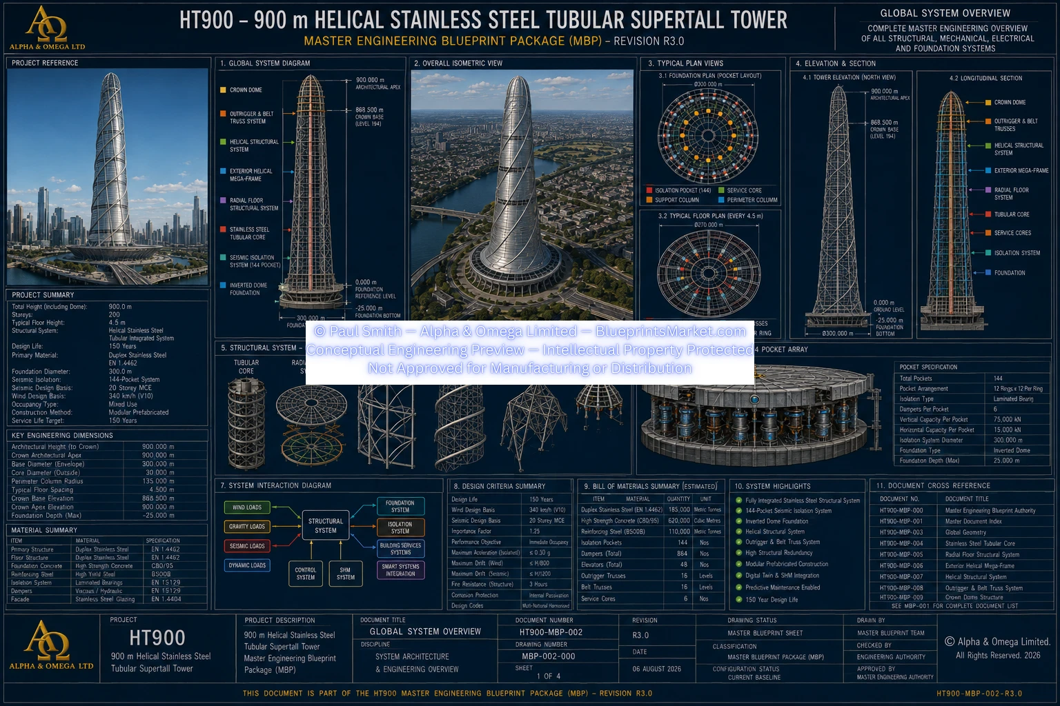
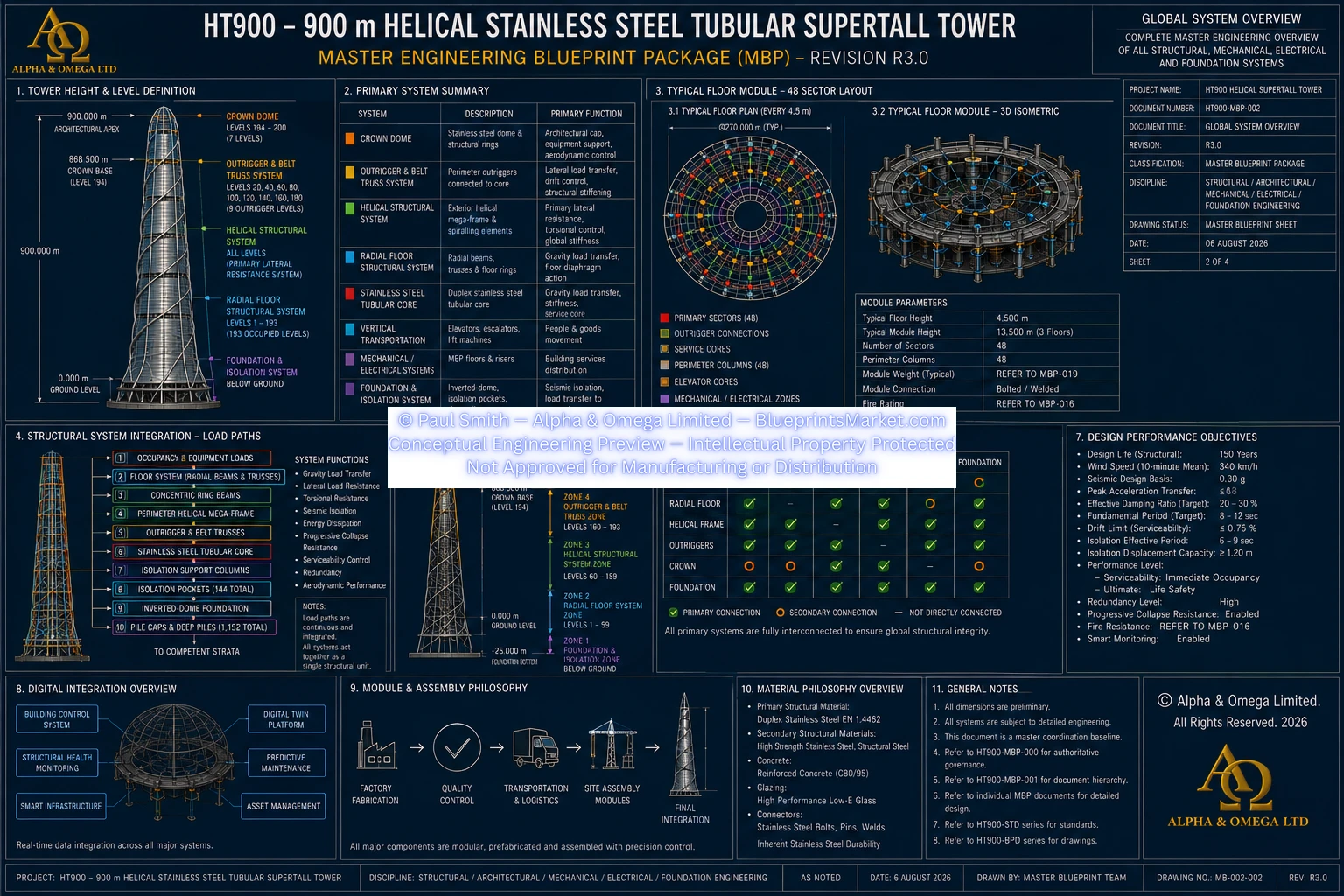
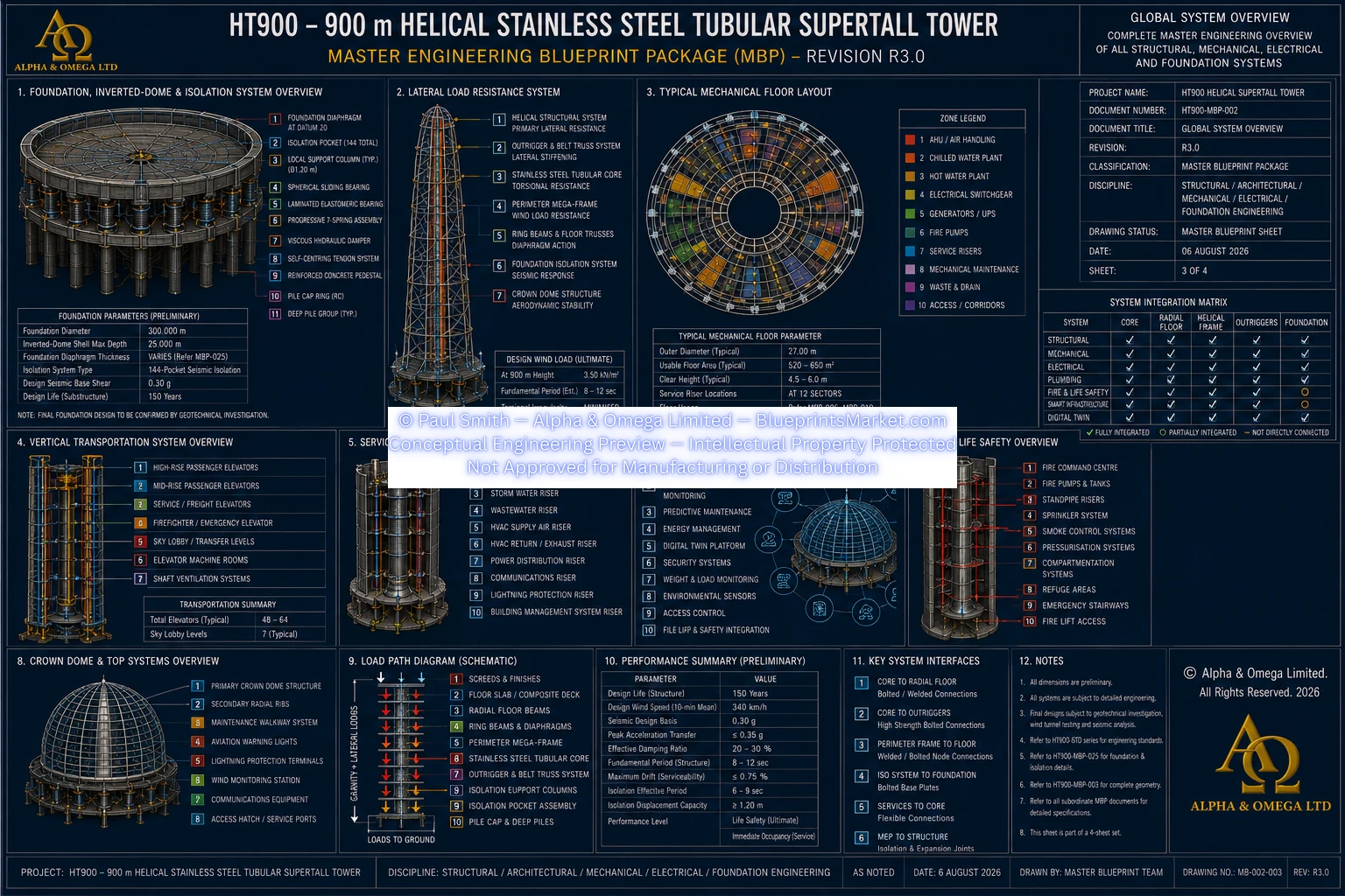
The HT900 R3.0 structural architecture is conceived as a unified three-dimensional stainless-steel tubular megastructure extending continuously from the deep foundation system to the 900 metre architectural crown.
Unlike conventional supertall buildings that commonly use a reinforced-concrete structural core working with separate perimeter framing, the HT900 integrates its Stainless Steel Tubular Core, Radial Floor Structural System, Exterior Helical Megaframe, Helical Structural System, Concentric Structural Support Rings, Outrigger & Belt-Truss System, Crown Dome Structure and Isolation Foundation into one coordinated structural framework.
Every principal structural subsystem participates in the transfer and redistribution of gravity, wind, seismic, torsional and dynamic loading while providing structural redundancy and continuous load-path behaviour.
Primary Building Parameters
| Architectural Height | 900.0 metres including crown |
|---|---|
| Structural Levels | 200 |
| Typical Structural Level Spacing | 4.5 metres |
| Maximum Base Envelope Diameter | 300.0 metres |
| Maximum Base Envelope Radius | 150.0 metres |
| Perimeter Structural Radius at Base | 135.0 metres |
| Central Structural Core Outside Diameter | 30.0 metres |
| Primary Structural Grid | 48 sectors at 7.5° spacing |
| Primary Structural Material | Duplex Stainless Steel EN 1.4462 |
| Structural System | Integrated Tubular Megastructure |
| Foundation Type | Inverted-Dome Base-Isolation System |
| Primary Structural Design-Life Objective | 150 years |
6.1 Integrated Structural System Hierarchy
The HT900 structural hierarchy is based on permanently interconnected systems rather than independent structural components.
Principal Structural Systems
- Integrated Crown Dome Structure
- Upper Crown Hybrid Tuned Mass Damping System
- Continuous Exterior Helical Tubular Megaframe
- Dual Opposing Helical Structural Systems
- Forty-Eight Perimeter Structural Columns
- Outrigger Transfer Trusses
- Belt-Truss System
- Circumferential Structural Ring-Beam Network
- Forty-Eight Primary Radial Floor Sectors
- Four Concentric Structural Support Rings
- Composite Structural Floor Diaphragms
- Thirty-Metre Stainless Steel Tubular Core
- Isolation Support Structure
- 144 Isolation Pocket Assemblies
- 300-Metre Inverted-Dome Foundation
- Deep-Pile Foundation System
No principal structural subsystem is intended to function independently. Each works with adjacent systems to maintain structural continuity throughout the tower.
6.2 Global Structural Geometry
The complete structural system follows the controlled HT900 helical tapered circular geometry.
Principal Geometry
- 900 metre maximum architectural height
- 200 structural levels
- Levels 194–200 integrated into the crown structure
- 300 metre maximum base envelope diameter
- 270 metre perimeter-column centreline diameter at the base
- 30 metre central tubular structural core
- 48 primary perimeter structural sectors
- 7.5° primary angular spacing
- Four concentric floor-support rings
- Progressive taper toward the crown
- Continuous helical tower geometry
- 160° total helical rotation
The continuously rotating and progressively tapered configuration is coordinated with both the structural and aerodynamic behaviour of the tower.
6.3 Stainless Steel Tubular Core
The 30 metre outside-diameter Stainless Steel Tubular Core forms the principal internal structural spine of the HT900 tower.
The core consists of a continuous circular EN 1.4462 Duplex Stainless Steel structural shell extending from the foundation interface into the Crown Dome transition.
No reinforced-concrete structural core forms part of the HT900 superstructure.
Primary Core Functions
- Gravity-load resistance
- Lateral-force resistance
- Global torsional stiffness
- Radial floor-system support
- Outrigger structural coupling
- Vertical transportation accommodation
- Building-services distribution
- Fire-protection riser integration
- Communications infrastructure
- Structural monitoring integration
6.4 Radial Floor Structural System
Every typical structural level is divided into 48 primary radial structural sectors extending outward from the Stainless Steel Tubular Core toward the perimeter structural system.
The floor system does not rely upon a single unsupported radial span between the core and perimeter.
Instead, the radial floor structure is supported by four concentric structural support rings between the core interface and the perimeter structural frame.
Primary Functions
- Gravity-load transfer
- Structural diaphragm action
- Wind-load distribution
- Seismic-load distribution
- Torsional restraint
- Core-to-perimeter structural coupling
- Architectural floor support
- Building-services support
Typical Floor Structural Arrangement
- 48 primary radial truss lines
- 48 primary structural sectors
- Four concentric structural support rings
- Secondary stainless-steel floor framing
- Structural diaphragm bracing
- Profiled stainless-steel deck
- Reinforced-concrete composite topping
6.5 Concentric Structural Support Ring System
Four principal concentric structural support rings are incorporated into each typical structural level between the central core and perimeter frame.
Structural Functions
- Equalise radial structural loading
- Reduce unsupported radial floor spans
- Redistribute concentrated structural forces
- Increase diaphragm stiffness
- Improve torsional resistance
- Maintain circular structural geometry
- Improve structural redundancy
- Provide alternate load paths following local damage
The concentric ring system is one of the defining structural characteristics of the HT900 floor architecture.
6.6 Exterior Helical Tubular Megaframe
The exterior structural system forms a continuous Duplex Stainless Steel tubular megaframe around the perimeter of the tower.
The megaframe follows the helical and tapered architectural geometry and functions as a structural exoskeleton rather than a decorative façade element.
Primary Functions
- Gravity-load participation
- Lateral-load resistance
- Torsional rigidity
- Outrigger structural coupling
- Floor-diaphragm connection
- Façade structural support
- Aerodynamic structural integration
- Progressive-collapse redundancy
6.7 Helical Structural System
The HT900 incorporates dual opposing continuous helical structural systems extending through the primary tower structure.
These structural members are integrated directly with the perimeter megaframe, floor rings, radial framing and Crown Dome.
Structural Functions
- Gravity-load participation
- Wind resistance
- Torsional restraint
- Dynamic-load redistribution
- Structural continuity
- Aerodynamic integration
- Redundant alternate load paths
The helical structural system therefore forms part of the primary load-resisting architecture and is not merely an architectural exterior treatment.
6.8 Outrigger Transfer System
Major outrigger systems structurally couple the Stainless Steel Tubular Core to the perimeter megaframe.
Principal Distribution
- Main outrigger levels occur at approximately 20-floor intervals
- Typical vertical interval is approximately 90 metres
- Outriggers coordinate with major structural transfer zones
- Outrigger levels interface directly with the core and perimeter frame
Primary Functions
- Increase global tower stiffness
- Reduce overturning response
- Reduce lateral drift
- Couple core and perimeter structural behaviour
- Improve torsional resistance
- Improve structural redundancy
- Improve dynamic behaviour under wind and seismic loading
6.9 Belt-Truss System
Circumferential Belt-Truss systems provide additional structural coupling and force redistribution around the tower perimeter.
Principal Distribution
- Belt-Truss levels occur at approximately 10-floor intervals
- Main Belt-Truss and Outrigger systems coincide at approximately 20-floor intervals
- Intermediate Belt-Truss levels operate between principal outrigger zones
Primary Functions
- Connect perimeter structural columns
- Redistribute circumferential structural forces
- Improve global stiffness
- Improve torsional resistance
- Support structural redundancy
- Support core-to-perimeter load sharing
6.10 Integrated Crown Dome Structure
The Crown Dome occupies the final seven structural levels of the tower and forms the structural and aerodynamic termination of the HT900 megastructure.
| Integrated Crown Levels | 194–200 |
|---|---|
| Approximate Crown Base Elevation | 868.5 metres |
| Crown Apex | 900.0 metres |
Integrated Crown Systems
- Tubular crown structural framing
- Crown support rings
- Helical structural continuity
- Hybrid Tuned Mass Damper support system
- Mechanical-support interfaces
- Communications infrastructure
- Maintenance access
- Lightning-protection interfaces
The crown completes the principal structural load paths while also providing aerodynamic closure to the tower.
6.11 Foundation & Seismic-Isolation Structural System
The HT900 superstructure is supported by an integrated 300 metre inverted-dome foundation and distributed seismic-isolation system.
| Foundation Diameter | 300 metres |
|---|---|
| Foundation Radius | 150 metres |
| Maximum Inverted-Dome Depth | Approximately 25 metres |
| Isolation Pocket Assemblies | 144 |
| Isolation Pocket Rings | 4 concentric rings |
Foundation Structural Components
- Inverted reinforced-concrete dome foundation
- Isolation support structure
- 144 isolation pocket assemblies
- Isolation bearing systems
- Progressive spring systems
- Hydraulic damping systems
- Self-centering systems
- Pile-cap network
- Deep-pile foundation system
- Drainage and waterproofing systems
- Foundation monitoring provisions
Reinforced concrete is used within the foundation and designated substructure elements. It is not used as the tower's structural core.
6.12 Complete Structural Load-Path Philosophy
Continuous and redundant load paths are fundamental to the HT900 structural architecture.
Gravity Load Path
Occupancy and equipment → composite floor construction → secondary stainless-steel framing → primary radial floor trusses → concentric structural support rings → Stainless Steel Tubular Core + perimeter megaframe → foundation support structure → isolation pocket assemblies → pile caps → deep piles → competent founding strata.
Wind Load Path
Wind loading → façade system → exterior helical megaframe → circumferential ring network → helical structural system → floor diaphragms → Outrigger & Belt-Truss System → Stainless Steel Tubular Core → isolation foundation → deep piles.
Seismic Load Path
Ground motion → deep piles → pile caps → inverted-dome foundation → isolation pocket assemblies → isolation and damping systems → support structure → Stainless Steel Tubular Core → floor diaphragms → perimeter megaframe → complete superstructure.
Dynamic Wind-Response Path
Wind excitation → exterior megaframe → Helical Structural System → outriggers → Stainless Steel Tubular Core → crown support structure → Hybrid Tuned Mass Damper → controlled energy dissipation and reduced structural motion.
6.13 Structural Redundancy & Progressive-Load Redistribution
The complete HT900 structure is designed around multiple interconnected load paths so that structural demand can be redistributed through adjacent systems rather than concentrated within one isolated component.
Redundancy Features
- Continuous tubular Stainless Steel Core
- 48 primary radial structural sectors
- 48 perimeter structural columns
- Four concentric structural support rings
- Continuous perimeter framing
- Dual opposing helical structural systems
- Outrigger network
- Belt-Truss network
- Composite structural floor diaphragms
- Integrated Crown Dome Structure
- Continuous structural connection network
This interconnected arrangement provides alternate load paths intended to improve structural robustness and resilience against localised damage.
6.14 Structural Connection System
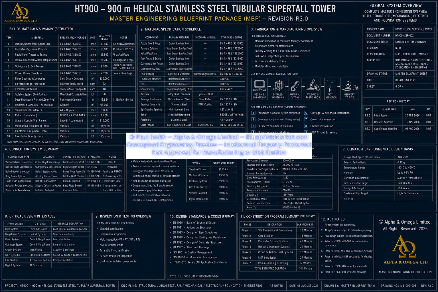
Major HT900 structural interfaces are governed by a coordinated Structural Connection Library covering the principal structural connection families throughout the tower.
The connection philosophy prioritises continuous structural load paths, permanent welded continuity, modular prefabrication, fatigue resistance, corrosion durability, inspection accessibility and replaceable interfaces where appropriate.
Principal Connection Types
- Core shell structural splices
- Core diaphragm connections
- Radial truss-to-core connections
- Radial truss-to-ring connections
- Perimeter-column splices
- Outrigger-to-core connections
- Outrigger-to-perimeter connections
- Belt-Truss structural nodes
- Helical-frame nodes
- Isolation-support interfaces
- Crown structural nodes
- Façade-support interfaces
Detailed connection geometry, plate sizes, fastener schedules, weld preparations and structural calculations remain within the applicable HT900 technical documentation and subsequent detailed engineering.
6.15 Structural Material Philosophy
The principal structural material throughout the HT900 superstructure is Duplex Stainless Steel EN 1.4462.
Primary Stainless-Steel Applications
- Stainless Steel Tubular Core
- Perimeter structural columns
- Exterior Helical Megaframe
- Helical structural members
- Radial floor trusses
- Concentric structural support rings
- Circumferential structural ring beams
- Outrigger systems
- Belt-Truss systems
- Crown structural framing
- Structural diaphragms
- Primary structural nodes and connections
Material Engineering Objectives
- High structural strength
- High fatigue resistance
- Corrosion resistance
- Long-term durability
- Reduced lifecycle maintenance
- Fabrication compatibility
- Inspection accessibility
Compatible Super Duplex Stainless Steel may be used at selected high-demand structural interfaces where required by detailed structural or corrosion engineering.
6.16 Modular Construction Philosophy
Major HT900 structural components are conceived for controlled factory manufacture followed by coordinated modular erection on site.
Principal Construction Objectives
- Controlled fabrication quality
- Improved dimensional accuracy
- Repeatable structural interfaces
- Controlled transportation
- Reduced uncontrolled field fabrication
- Progressive structural erection
- Improved construction safety
- Comprehensive inspection and quality assurance
Typical primary structural erection cycles are coordinated around 13.5 metre three-floor module groups.
Complete structural floors are assembled progressively from component sectors and are not intended to be transported or lifted as one complete floor module.
6.17 Aerodynamic & Dynamic Structural Integration
Structural response to wind is addressed through the coordinated interaction of tower geometry, structural stiffness, damping and monitoring rather than through one isolated structural device.
Integrated Dynamic Systems
- 160° helical tower geometry
- Progressive structural taper
- Exterior Helical Megaframe
- Helical Structural System
- Stainless Steel Tubular Core
- Outrigger & Belt-Truss System
- Crown Dome Structure
- Hybrid Tuned Mass Damper
- Structural Health Monitoring
Final wind performance, dynamic response and façade pressures require project-specific computational analysis, physical wind-tunnel testing and structural dynamic verification.
6.18 Seismic Structural Philosophy
Seismic resilience within the HT900 concept is achieved through a combination of continuous structural load paths, high structural redundancy, the distributed foundation-isolation system, energy dissipation and structural monitoring.
Primary Seismic Features
- 144 distributed isolation pocket assemblies
- Four concentric isolation rings
- Isolation bearing systems
- Progressive spring assemblies
- Hydraulic damping systems
- Self-centering systems
- Continuous Stainless Steel Tubular Core
- Continuous perimeter megaframe
- Four concentric floor-support rings
- Radial structural diaphragms
- Helical structural systems
- Outrigger and Belt-Truss networks
- Structural monitoring provisions
6.19 Structural Monitoring & Lifecycle Philosophy
The HT900 complete structural architecture incorporates permanent provisions for inspection, condition monitoring and long-term structural asset management.
Monitoring & Inspection Concepts
- Structural strain monitoring
- Acceleration monitoring
- Displacement monitoring
- Structural vibration monitoring
- Temperature monitoring
- Corrosion-condition monitoring
- Foundation and settlement monitoring
- Connection inspection
- Weld inspection
- Long-term structural survey
- Condition-based maintenance planning
| Primary Structural Design-Life Objective | 150 years |
|---|---|
| Primary Structural Material | Duplex Stainless Steel EN 1.4462 |
| Maintenance Philosophy | Inspectable, monitored and lifecycle-managed |
6.20 Complete Structural Engineering Summary
The HT900 complete structural system is founded on the principle that the tower behaves as one continuous, interconnected structural megastructure.
- The 30 metre Stainless Steel Tubular Core forms the principal internal structural spine.
- 48 radial structural sectors and four concentric structural support rings distribute loads between the core and perimeter structure.
- The 48-column Exterior Helical Megaframe provides a continuous perimeter structural system.
- Dual opposing helical structural systems provide structural and aerodynamic integration throughout the height of the tower.
- Outriggers and Belt Trusses couple the central core to the perimeter structure and improve global stiffness and load redistribution.
- The Integrated Crown Dome completes the primary structural load paths and supports the upper dynamic-control systems.
- The 300 metre inverted-dome foundation and 144-pocket seismic-isolation system form the principal structural interface between the superstructure and deep foundation.
- Continuous structural connections, modular fabrication, inspection access and monitoring support long-term structural reliability and the 150-year primary structural design-life objective.
6.21 Professional Engineering Notice
The HT900 Complete Structural System forms part of the HT900 R3.0 conceptual Master Blueprint Package.
This public page summarises the principal structural architecture, locked global geometry, major structural systems, load-path philosophy, material strategy, foundation concept, construction philosophy and lifecycle engineering objectives.
Detailed member sizes, shell-thickness schedules, structural-node geometry, connection calculations, fastener schedules, welding details, foundation reinforcement, isolation-component dimensions, fabrication tolerances, structural calculations and other implementation-level engineering information remain within the applicable HT900 technical documentation or require subsequent project-specific professional engineering.
The HT900 Master Blueprint Package is a conceptual engineering reference and is not a certified construction drawing package.
Any real-world implementation requires complete site-specific architectural and structural engineering, geotechnical investigation, nonlinear structural analysis, wind-tunnel testing, seismic analysis, fire engineering, detailed connection design, fabrication and construction documentation, independent professional review, regulatory approval and certification by appropriately qualified and licensed engineering professionals.
HT900-MBP-002 — GLOBAL SYSTEM OVERVIEW
Copyright — Alpha & Omega Limited
All blueprint files, CAD parameters, architectural concepts, engineering specifications, and written content are the exclusive intellectual property of Alpha & Omega Limited. No part of the Stainless‑Steel Skyscraper Blueprint Package may be reproduced, distributed, or adapted without written consent.
Licensing, Copyright & Patent Restrictions
This engineering system and all associated blueprint materials, CAD files, diagrams, schematics, dimensional tables, and technical narratives are licensed, not sold, and remain the exclusive intellectual property of Alpha & Omega Limited.
This product is not eligible for patenting by any purchaser, user, organization, or third party. Patent filings, provisional patents, utility models, derivative patents, reverse‑engineering for patent purposes, and intellectual property claims are strictly prohibited.
Redistribution, resale, sublicensing, public posting, dataset inclusion, or any form of unauthorized duplication of blueprint materials, CAD files, diagrams, or engineering concepts is strictly prohibited. No license tier grants ownership, patent rights, or rights to file for intellectual property protection.
All architectural & engineering systems are conceptual and require full professional engineering validation before any real‑world use, construction, prototyping, or structural implementation.
Full legal details are available in the Terms & Conditions .