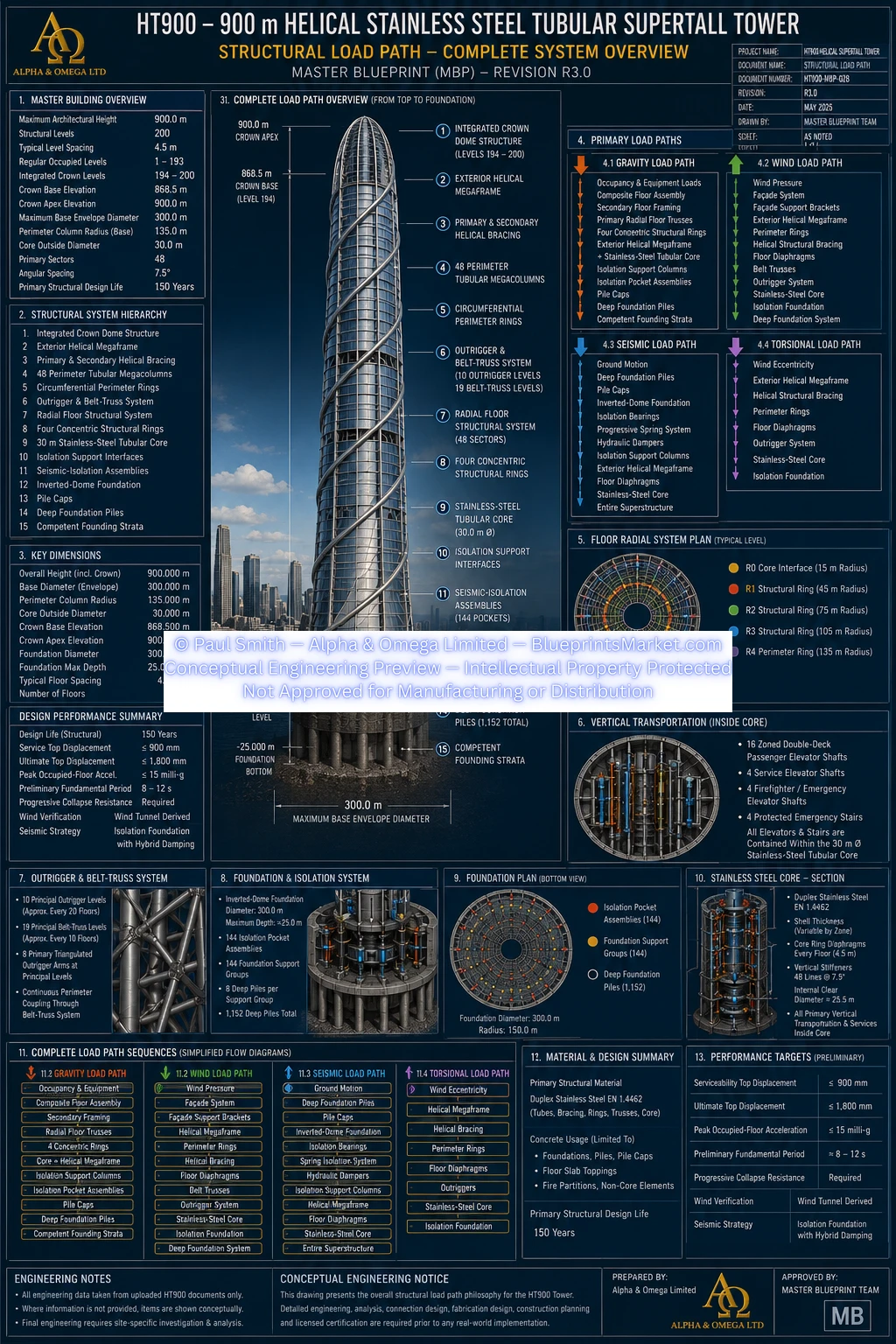
Structural Load Path — HT900 Helical Stainless-Steel Tubular Supertall
900 m • 200 Structural Levels • 300 m Maximum Base Envelope • Integrated Tubular Stainless-Steel Megastructure
1.0 Complete Structural Load Path Overview
The HT900 is a 900-metre Helical Stainless-Steel Tubular Supertall Tower developed around a continuous, redundant and fully integrated three-dimensional structural load-transfer system.
Gravity, wind, seismic, torsional and dynamic forces are not resisted by one isolated structural component. Instead, the tower's major structural systems work together to distribute forces through multiple interconnected load paths from the occupied floors and crown to the foundation and competent founding strata.
The principal structural load-resisting systems include the 30-metre Duplex Stainless-Steel Tubular Core, radial floor structural system, four concentric structural support rings, Exterior Helical Megaframe, opposing helical bracing systems, 48 perimeter megacolumns, Outrigger & Belt-Truss System, integrated Crown Dome Structure, seismic-isolation system, inverted-dome foundation and deep-foundation system.
The central structural core is entirely tubular stainless steel. No reinforced-concrete structural core is used in the HT900.
2.0 Governing Structural Geometry
| Maximum Architectural Height | 900 m |
|---|---|
| Structural Levels | 200 |
| Typical Structural Level Spacing | 4.5 m |
| Regular Occupied Levels | Levels 1–193 |
| Integrated Crown Levels | Levels 194–200 |
| Crown Base Elevation | Approximately 868.5 m |
| Crown Apex | 900 m |
| Maximum Base Envelope Diameter | 300 m |
| Perimeter-Column Centreline Radius | 135 m at base |
| Tubular Structural Core Diameter | 30 m |
| Primary Structural Grid | 48 sectors |
| Primary Angular Spacing | 7.5° |
| Total Helical Rotation | 160° |
| Primary Structural Design Life | 150 years |
3.0 Structural Load-Path Hierarchy
The HT900 structural hierarchy connects the complete building from the architectural apex to the supporting ground.
- Integrated Crown Dome Structure
- Exterior Helical Megaframe
- Primary and Secondary Helical Structural Bracing
- 48 Perimeter Tubular Megacolumns
- Circumferential Perimeter Rings
- Outrigger & Belt-Truss System
- Radial Floor Structural System
- Four Concentric Structural Support Rings
- 30 m Duplex Stainless-Steel Tubular Core
- Isolation Support Interfaces
- Seismic-Isolation Assemblies
- Inverted-Dome Foundation
- Pile Caps
- Deep Foundation Piles
- Competent Founding Strata
These systems operate as one coordinated structural network rather than as independent structures.
4.0 Gravity Load Path
The governing HT900 gravity-load path transfers occupancy, equipment and permanent building loads through the floor structure, into the shared central and perimeter structural systems, and ultimately into the deep foundation.
Occupancy & Equipment Loads
↓
Architectural Floor Finishes
↓
Composite Concrete Topping
↓
Stainless-Steel Profiled Floor Deck
↓
Secondary Floor Framing
↓
Primary Radial Floor Trusses
↓
Four Concentric Structural Support Rings
↓
Exterior Helical Megaframe + Stainless-Steel Tubular Core
↓
Isolation Support Columns
↓
Isolation Pocket Assemblies
↓
Pile Caps
↓
Deep Foundation Piles
↓
Competent Founding Strata
5.0 Floor Structural Load Path
Each typical structural floor is divided into 48 primary radial sectors rather than being treated as one transportable floor assembly.
The primary radial floor system distributes gravity and diaphragm forces through a sequence of concentric structural support rings.
| Core Interface | 15 m radius |
|---|---|
| Structural Ring R1 | 45 m radius |
| Structural Ring R2 | 75 m radius |
| Structural Ring R3 | 105 m radius |
| Perimeter Ring R4 | 135 m radius |
This creates approximately 30-metre radial structural bays, avoiding the obsolete concept of a single unsupported core-to-perimeter floor span.
The simplified floor load path is:
Composite Floor → Stainless-Steel Deck → Secondary Framing → Radial Trusses → Concentric Rings → Core + Perimeter Frame → Foundation
6.0 Shared Core & Megaframe Gravity Path
The HT900 does not transfer all gravity loading exclusively into the central core.
The Stainless-Steel Tubular Core and Exterior Helical Megaframe form a shared primary vertical load path.
Floor reactions are distributed between these systems through radial floor framing, circumferential rings, floor diaphragms and major transfer structures.
This shared structural philosophy provides redundancy and prevents the complete tower gravity-load demand from being concentrated within one central vertical element.
7.0 Stainless-Steel Tubular Core Load Path
The central core is a continuous circular tubular structural shell fabricated from Duplex Stainless Steel EN 1.4462.
The core receives forces from:
- Radial floor framing
- Floor diaphragms
- Outrigger structures
- Belt-truss coupling
- Vertical transportation support systems
- Internal structural diaphragms
- Upper crown structural systems
Core ring diaphragms located at each structural floor distribute local floor and outrigger reactions into the tubular shell while helping restrain shell ovalisation.
The core then transfers structural reactions vertically toward the foundation and seismic-isolation system.
8.0 Exterior Helical Megaframe Load Path
The Exterior Helical Megaframe forms one of the principal structural load-carrying systems within the HT900 tower.
It incorporates:
- 48 perimeter tubular megacolumn lines
- Two opposing primary helical brace families
- Secondary helical structural bracing
- Circumferential perimeter rings
- Structural node assemblies
- Floor-truss interfaces
- Outrigger interfaces
- Belt-truss interfaces
- Crown transition structures
- Foundation support interfaces
The megaframe participates in gravity, wind, seismic, torsional and overturning load transfer.
9.0 Wind Load Path
Wind pressure acting on the architectural envelope is transferred into the primary structural system through the façade support network.
Wind Pressure
↓
Façade System
↓
Façade Support Brackets
↓
Exterior Helical Megaframe
↓
Circumferential Perimeter Rings
↓
Helical Structural Bracing
↓
Floor Diaphragms
↓
Belt Trusses
↓
Outrigger System
↓
Stainless-Steel Tubular Core
↓
Isolation Foundation
↓
Deep Foundation System
10.0 Façade-to-Structure Load Interface
The HT900 exterior cladding and curtain-wall system is a secondary environmental envelope mounted outside the tubular stainless-steel structural megaframe.
It does not form the primary global structural frame.
Wind pressure and façade dead loads are transferred through engineered façade support brackets into the Exterior Helical Megaframe.
Façade attachment systems must accommodate differential structural movement while maintaining weather protection and load-transfer continuity.
11.0 Torsional Load Path
Because the HT900 is a tapered helical tower, torsional forces form an important part of its global structural behaviour.
The governing torsional load path is:
Wind Eccentricity
↓
Exterior Helical Megaframe
↓
Helical Bracing
↓
Perimeter Rings
↓
Floor Diaphragms
↓
Outriggers
↓
Stainless-Steel Tubular Core
↓
Isolation Foundation
Opposing helical structural families allow torsional actions to be redistributed continuously through the exterior structural network rather than concentrated at isolated braces.
12.0 Outrigger & Belt-Truss Load Transfer
The Outrigger & Belt-Truss System couples the central Stainless-Steel Tubular Core with the exterior perimeter structure.
The current HT900 baseline incorporates:
- 10 principal outrigger levels
- Principal outriggers approximately every 20 floors
- 19 principal belt-truss levels
- Belt trusses approximately every 10 floors
- Eight primary triangulated outrigger arms at principal levels
- Continuous perimeter coupling through the belt-truss system
Under lateral loading, the outriggers transfer core overturning action into axial tension and compression within the perimeter megacolumn system.
Core Overturning Action
↓
Core Transfer System
↓
Primary Outriggers
↓
Belt Truss
↓
Perimeter Megacolumns
↓
Foundation System
13.0 Floor Diaphragm Load Transfer
Completed floors act as flexible but highly stiffened composite diaphragms.
They are not assumed to behave as perfectly rigid plates.
Floor diaphragms distribute:
- Wind-induced in-plane shear
- Seismic diaphragm forces
- Torsional actions
- Gravity-load redistribution
- Forces between the core and perimeter structure
- Local structural redistribution following component damage
14.0 Seismic Load Path
The HT900 seismic load path begins with ground motion at the deep-foundation system and progresses upward through the foundation, isolation system and complete superstructure.
Ground Motion
↓
Deep Foundation Piles
↓
Pile Caps
↓
Reinforced-Concrete Inverted-Dome Foundation
↓
Isolation Bearings
↓
Progressive Spring Isolation System
↓
Hydraulic Dampers
↓
Isolation Support Columns
↓
Exterior Helical Megaframe
↓
Floor Diaphragms
↓
Stainless-Steel Tubular Core
↓
Entire Superstructure
15.0 Foundation & Substructure Load Path
The foundation forms the final major structural transfer system between the HT900 superstructure and the supporting ground.
| Foundation Form | Concave Inverted Reinforced-Concrete Dome |
|---|---|
| Foundation Diameter | 300 m |
| Foundation Radius | 150 m |
| Approximate Maximum Dome Depth | 25 m |
| Isolation Pockets | 144 |
| Foundation Support Groups | 144 |
| Deep Piles per Support Group | 8 |
| Total Deep Piles | 1,152 |
Reinforced concrete is used in the foundation and deep substructure. This does not conflict with the all-stainless-steel structural-core requirement, because the prohibition applies specifically to the tower's primary structural core and above-foundation framing.
16.0 Seismic-Isolation Load Transfer
The foundation incorporates 144 coordinated seismic-isolation pocket assemblies.
The isolation system separates several structural functions rather than relying upon one component to perform every task.
Primary Isolation Functions
- Gravity-load support
- Controlled horizontal movement
- Seismic energy dissipation
- Progressive restoring force
- Self-centering behaviour
- Rotation accommodation
These functions are provided through coordinated bearing, spring, hydraulic damping and self-centering systems.
17.0 Deep Foundation Load Transfer
The deep-foundation system receives concentrated and distributed reactions from the pile caps and transfers those reactions into competent founding strata.
The current conceptual baseline contains 144 foundation support groups with eight deep piles assigned to each group, producing 1,152 piles in total.
Final pile length, capacity, reinforcement and geotechnical behaviour remain dependent upon site-specific investigation and detailed foundation engineering.
18.0 Crown Structural Load Path
The HT900 Crown Dome occupies Levels 194–200 and forms the structural and aerodynamic termination of the tower.
Crown loads are not transferred through a separate decorative shell. The crown remains integrated directly with:
- Upper Stainless-Steel Tubular Core
- Exterior Helical Megaframe
- Primary crown ribs
- Helical crown structural members
- Circumferential crown rings
- Upper floor structural systems
Gravity, wind, equipment and dynamic crown reactions therefore continue into the same principal structural systems used throughout the tower below.
19.0 Vertical Transportation Structural Interface
All principal elevators and protected emergency stairs are contained within the 30-metre Stainless-Steel Tubular Core.
The core contains:
- 16 zoned double-deck passenger elevator shafts
- 4 service elevator shafts
- 4 dedicated firefighter / emergency elevator shafts
- 4 protected emergency stairs
Elevator operational loads are transferred directly into the internal structural framework of the Stainless-Steel Tubular Core.
They are not intentionally transferred into the exterior curtain wall, primary radial floor trusses or exterior helical framing.
20.0 Building Services & Structural Load Interfaces
Major vertical mechanical, electrical, communications, hydraulic and fire-service risers are coordinated inside the Stainless-Steel Tubular Core.
Horizontal services distribute outward through coordinated floor and service zones.
Service equipment and support loads are transferred into designated structural support points without cutting or compromising the primary tubular stainless-steel structure.
21.0 Structural Redundancy & Alternative Load Paths
The HT900 is intentionally designed around multiple interacting structural load paths.
Structural redundancy is provided through:
- 30 m Tubular Stainless-Steel Core
- 48 perimeter megacolumns
- 48 radial floor structural sectors
- Four concentric structural support rings
- Two opposing helical brace families
- Secondary helical structural bracing
- Circumferential perimeter rings
- Outrigger systems
- Belt-truss systems
- Floor diaphragm action
- Integrated crown structure
- Distributed foundation support system
Local structural forces can therefore be redistributed through adjacent radial sectors, circumferential rings and other major load-resisting systems.
22.0 Complete Gravity Load-Transfer Sequence
Occupancy / Equipment / Architectural Loads
↓
Composite Floor Assembly
↓
Secondary Stainless-Steel Floor Framing
↓
Primary Radial Floor Trusses
↓
Four Concentric Structural Support Rings
↓
Stainless-Steel Tubular Core + Exterior Helical Megaframe
↓
Isolation Support Columns
↓
Isolation Pocket Assemblies
↓
Pile Caps
↓
Deep Foundation Piles
↓
Competent Founding Strata
23.0 Complete Wind Load-Transfer Sequence
Wind Pressure
↓
Façade System
↓
Façade Support Brackets
↓
Exterior Helical Megaframe
↓
Circumferential Perimeter Rings
↓
Helical Structural Bracing
↓
Floor Diaphragms
↓
Belt Trusses
↓
Outrigger System
↓
Stainless-Steel Tubular Core
↓
Isolation Foundation
↓
Deep Foundation
24.0 Complete Seismic Load-Transfer Sequence
Ground Motion
↓
Deep Foundation Piles
↓
Pile Caps
↓
Reinforced-Concrete Inverted-Dome Foundation
↓
Isolation Bearings
↓
Progressive Spring Isolation System
↓
Hydraulic Dampers
↓
Isolation Support Columns
↓
Exterior Helical Megaframe
↓
Floor Diaphragms
↓
Stainless-Steel Tubular Core
↓
Entire Superstructure
25.0 Complete Torsional Load-Transfer Sequence
Wind Eccentricity / Torsional Excitation
↓
Exterior Helical Megaframe
↓
Helical Structural Bracing
↓
Perimeter Structural Rings
↓
Floor Diaphragms
↓
Outrigger System
↓
Stainless-Steel Tubular Core
↓
Isolation Foundation
26.0 Global Structural Performance Targets
The current conceptual HT900 engineering baseline establishes the following preliminary global performance targets.
| Primary Structural Design Life | 150 years |
|---|---|
| Serviceability Top Displacement | ≤ 900 mm target |
| Ultimate Top Displacement | ≤ 1,800 mm target |
| Peak Occupied-Floor Acceleration | ≤ 15 milli-g target |
| Preliminary Fundamental Period | Approximately 8–12 seconds |
| Progressive Collapse Resistance | Required |
| Structural Redundancy | Multiple Independent Load Paths |
| Wind Verification | Wind-Tunnel Derived |
| Seismic Strategy | Isolation Foundation with Hybrid Damping |
These values are conceptual engineering targets and require validation through complete structural analysis, dynamic modelling and physical testing.
27.0 Structural Health Monitoring
Structural load-path behaviour is monitored through the HT900 Structural Health Monitoring and Digital Twin architecture.
Monitoring may include:
- Core strain and deformation
- Perimeter-column response
- Outrigger and belt-truss behaviour
- Floor diaphragm response
- Isolation-pocket movement
- Foundation behaviour
- Wind response
- Structural acceleration
- Long-term structural movement
- Connection performance
Digital lifecycle records support inspection, maintenance and long-term structural condition assessment.
28.0 Licensed Engineering Documentation
This public page explains the overall structural load-path philosophy of the HT900 tower.
Detailed engineering information contained within the licensed HT900 Master Blueprint Package includes substantially greater subsystem definition and is intentionally not reproduced here.
Licensed technical documentation may include:
- Structural member schedules
- Tube diameters and wall-thickness schedules
- Structural-node geometry
- Connection and transfer-zone engineering
- Foundation and isolation-component specifications
- Fastener schedules
- Welding requirements
- Fabrication and erection requirements
- Structural monitoring requirements
- Inspection requirements
- Detailed subsystem drawings
- Conceptual engineering calculations and specifications
29.0 Structural Load Path Summary
The HT900 structural philosophy is based on continuous, redundant and interconnected load paths.
Gravity loads pass from the composite floor system through secondary framing, primary radial floor trusses, four concentric structural support rings and into a shared structural load path formed by the Stainless-Steel Tubular Core and Exterior Helical Megaframe.
Wind forces pass from the façade through façade supports, the Exterior Helical Megaframe, perimeter rings, helical bracing, floor diaphragms, belt trusses, outriggers and the Stainless-Steel Tubular Core before reaching the isolation foundation and deep foundation.
Seismic forces travel upward from the ground through the deep piles, pile caps, inverted-dome foundation, isolation bearings, spring system, hydraulic dampers and isolation support columns before being distributed through the Exterior Helical Megaframe, floor diaphragms, Stainless-Steel Tubular Core and complete superstructure.
Torsional actions are distributed through the Exterior Helical Megaframe, opposing helical structural systems, perimeter rings, floor diaphragms, outriggers and Stainless-Steel Tubular Core.
Together these systems create a continuous three-dimensional structural hierarchy extending from the 900-metre crown apex to competent founding strata.
30.0 Conceptual Engineering Notice
The HT900 is presented as an advanced conceptual engineering and architectural blueprint system.
The structural load paths shown on this public page describe the intended relationships between the principal HT900 structural subsystems and do not constitute construction-certified structural calculations.
Any real-world implementation requires complete site-specific geotechnical investigation, nonlinear finite-element analysis, seismic analysis, soil-structure interaction analysis, wind-tunnel testing, Computational Fluid Dynamics, dynamic-response analysis, connection engineering, fatigue assessment, foundation engineering, fabrication engineering, construction-stage analysis, fire engineering and independent professional verification.
Final structural design, fabrication and construction must be reviewed, approved and certified by appropriately qualified and licensed engineering professionals in accordance with the laws, codes, standards and site conditions applicable to the actual project location.