
1.0 Smart Infrastructure System Overview
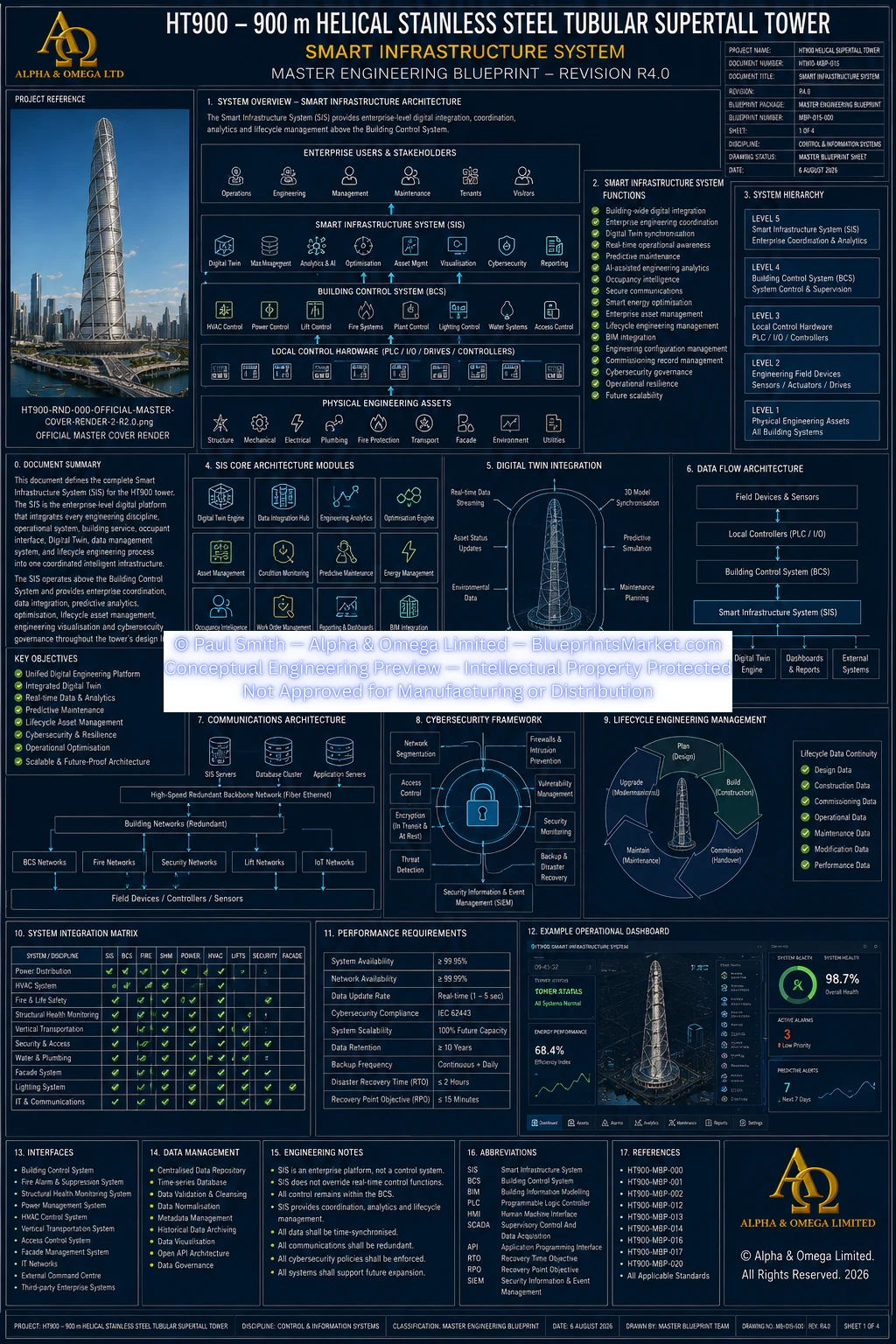
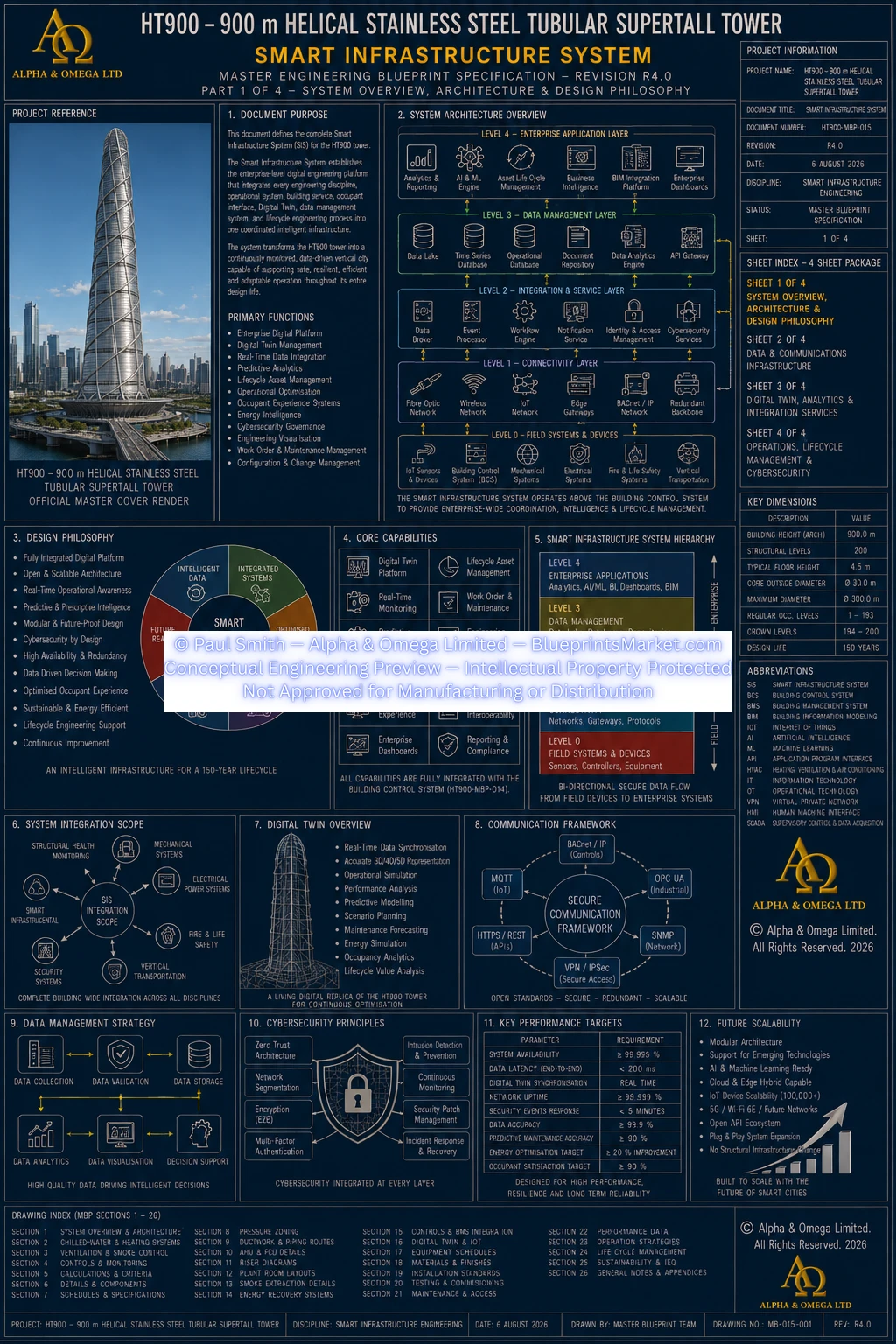
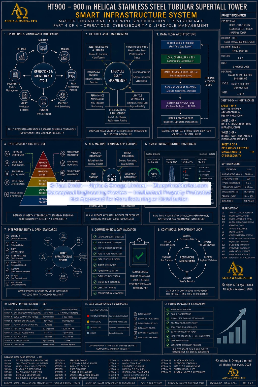
The HT900 Smart Infrastructure System (SIS) forms the enterprise-level digital engineering platform for the 900 metre Helical Stainless Steel Tubular Supertall Tower.
It integrates engineering disciplines, operational systems, building services, Digital Twin information, enterprise data, asset-management systems and lifecycle engineering processes into one coordinated intelligent infrastructure.
The Smart Infrastructure System is intentionally separated from the Building Control System.
The Building Control System performs deterministic real-time control of physical equipment, while the Smart Infrastructure System provides enterprise-wide coordination, data integration, predictive analytics, Digital Twin management, optimisation, lifecycle asset management, engineering visualisation, cybersecurity governance and operational intelligence.
Principal Smart Infrastructure Functions
- Building-wide digital integration
- Enterprise engineering coordination
- Digital Twin synchronisation
- Real-time operational awareness
- Predictive maintenance
- AI-assisted engineering analytics
- Occupancy intelligence
- Smart energy optimisation
- Enterprise asset management
- Lifecycle engineering management
- BIM integration
- Engineering configuration management
- Cybersecurity governance
- Operational resilience
- Future technology scalability
2.0 Building Control System & Smart Infrastructure Relationship
The HT900 digital architecture separates real-time physical control from enterprise-level engineering intelligence.
| Building Control System | Smart Infrastructure System |
|---|---|
| Deterministic equipment control | Enterprise engineering coordination |
| PLC and controller supervision | Enterprise data integration |
| HVAC automation | Digital Twin management |
| Power-system control | Engineering analytics |
| Pump and plant sequencing | Predictive maintenance |
| Equipment interlocking | Lifecycle asset management |
| Emergency operating modes | AI-assisted operational analysis |
This separation allows critical equipment to retain deterministic local and building-level control while enterprise systems analyse, coordinate and optimise information without becoming the primary control mechanism for safety-critical equipment.
3.0 Six-Layer Smart Infrastructure Architecture
The HT900 Smart Infrastructure System uses a distributed six-layer architecture separating physical infrastructure, operational control, enterprise analytics and authorised user services.
Layer 1 — Physical Infrastructure
Layer 1 contains the physical devices and engineering systems generating operational information throughout the tower.
- Structural Health Monitoring sensors
- HVAC instrumentation
- Electrical meters
- Power-quality analysers
- Flow and pressure instrumentation
- Temperature and humidity sensors
- Air-quality sensors
- Occupancy sensors
- Lift-monitoring devices
- Security-system interfaces
- Fire-detection interfaces
- Water-quality monitoring
- Energy meters
- Smart-lighting controllers
- Environmental monitoring equipment
- Weather and wind instrumentation
- Foundation monitoring
- Seismic instrumentation
Layer 2 — Edge Computing
Distributed edge computing provides local data processing close to engineering equipment, reducing communications traffic and maintaining selected processing functions during temporary network interruptions.
- Sensor aggregation
- Local analytics
- Data filtering
- Temporary buffering
- AI inference
- Local Digital Twin synchronisation
- Alarm preprocessing
- Equipment diagnostics
- Communications optimisation
- Cybersecurity monitoring
Layer 3 — Communications Network
The communications layer connects engineering systems, edge computing, enterprise applications, data platforms and authorised interfaces through resilient fibre-optic and industrial communications infrastructure.
Layer 4 — Central Data Platform
The Central Data Platform consolidates information from the building's engineering disciplines into a coordinated enterprise digital environment.
- Enterprise databases
- Historical engineering data
- Digital Twin services
- AI services
- Engineering analytics
- Configuration management
- Lifecycle asset records
- Predictive maintenance
- Energy optimisation
- Operational dashboards
- Reporting services
- Data governance
Layer 5 — Building Applications
Enterprise applications transform engineering information into operational intelligence and decision support.
- Asset Management
- Maintenance Management
- Energy Management
- Occupancy Analytics
- Visitor Management
- Space Utilisation
- Security Management
- Environmental Analytics
- Sustainability Reporting
- Operational Performance Monitoring
- Engineering Reporting
- Lifecycle Planning
Layer 6 — User Interfaces
Authorised personnel access engineering information through role-specific interfaces.
- Building Operations Centre
- Engineering workstations
- Mobile maintenance devices
- Executive dashboards
- Emergency Operations Centre
- Asset-management portals
- Tenant-service portals
- Digital Twin visualisation systems
4.0 Distributed Edge Computing
Edge computing distributes processing throughout the tower rather than requiring every data stream to be processed exclusively by central enterprise infrastructure.
Conceptual Distribution
- Normally one edge computing node per occupied floor
- Additional nodes within plant rooms
- Additional nodes at major mechanical floors
- Additional nodes at electrical distribution levels
- Dedicated Crown Structure nodes
- Dedicated Data Centre gateway nodes
- Security gateway nodes
- Fire & Life Safety gateway interfaces
Final node quantities and hardware configurations are determined during detailed engineering.
Edge Resilience
- Local data buffering
- Automatic synchronisation
- Software redundancy
- Secure firmware management
- Health monitoring
- Watchdog supervision
- Automatic recovery
- Modular hardware replacement
Temporary network interruptions are not intended to result in permanent loss of engineering information.
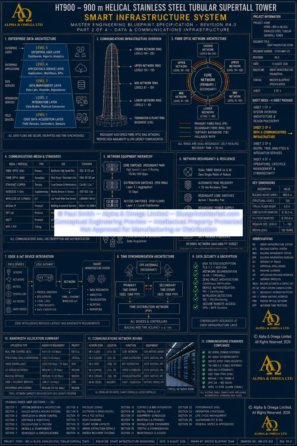
5.0 Enterprise Communications Infrastructure
The Smart Infrastructure communications network provides the primary digital transport layer connecting the tower's engineering disciplines and enterprise services.
Primary Fibre Backbone
- Dual OS2 single-mode fibre-optic rings
- Geographically diverse routing where practical
- Automatic communications failover
- Redundant communications rooms
- Redundant aggregation switching
- Segregated engineering networks
- Future bandwidth expansion capability
Conceptual Communications Performance
| Backbone Capacity | 400 Gbps minimum scalable capacity |
|---|---|
| Floor Distribution | 40 Gbps fibre distribution |
| Equipment Connections | 1–10 Gbps industrial Ethernet as appropriate |
| Wireless Infrastructure | Enterprise-grade Wi-Fi 7 or later approved technology |
| Target Ring Recovery | < 50 ms |
| Target Local Latency | < 20 ms |
Final communications performance is subject to detailed network engineering and project-specific verification.
6.0 Network Segmentation
Independent logical networks separate critical engineering, enterprise and public communications services while permitting controlled interoperability where required.
Principal Network Domains
- Building Control System
- Fire & Life Safety
- Security Systems
- Smart Infrastructure
- Digital Twin
- Structural Health Monitoring
- Enterprise IT
- Tenant services
- Public communications
Network Engineering Principles
- Deterministic routing
- Quality of Service
- Traffic prioritisation
- Multicast optimisation
- Software-defined networking where adopted
- Future bandwidth expansion
- Fibre redundancy
- Maintenance isolation
- Cybersecurity monitoring
7.0 Central Data Platform
The Central Data Platform provides the principal enterprise information repository for the HT900 Smart Infrastructure System.
It consolidates operational information from the tower's engineering disciplines while maintaining traceability, configuration control, historical records and secure data management.
Data Integrity Functions
- Timestamp synchronisation
- Engineering validation
- Version control
- Audit trails
- Secure backups
- Data verification
- Automatic error detection
- Recovery capability
Engineering records remain traceable throughout the operational life of their corresponding assets.
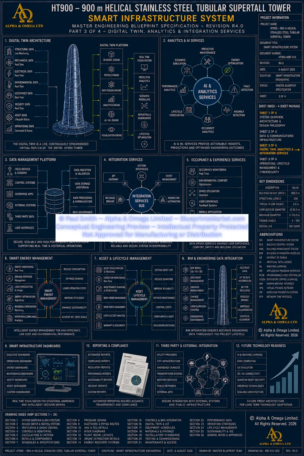
8.0 Enterprise Digital Twin
The Smart Infrastructure System incorporates a continuously synchronised Digital Twin representing the engineering state of the HT900 throughout its operational lifecycle.
Unlike a conventional static three-dimensional BIM model, the Digital Twin continuously receives information from live engineering systems and maintains an operational representation of the physical tower.
Digital Twin Functions
- Real-time engineering visualisation
- Building-wide operational awareness
- Structural-performance monitoring
- Environmental monitoring
- Energy analysis
- Predictive maintenance
- Asset lifecycle management
- Configuration management
- Engineering change management
- Operational simulation
- Failure analysis
- Emergency-response support
- Long-term engineering records
Integrated Engineering Systems
- Stainless Steel Tubular Core
- Exterior Helical Megaframe
- Foundation systems
- Mechanical systems
- Electrical systems
- Plumbing systems
- HVAC systems
- Fire & Life Safety systems
- Vertical transportation
- Communications infrastructure
- Security systems
- Renewable-energy systems
- Water-management systems
9.0 BIM & Engineering Configuration Management
The Digital Twin remains coordinated with the approved Building Information Model throughout the tower lifecycle.
BIM Information
- Design geometry
- Construction information
- Equipment locations
- Material specifications
- Engineering schedules
- Manufacturer information
- Installation records
Lifecycle Engineering Records
- Factory Acceptance Testing records
- Site Acceptance Testing records
- Commissioning documentation
- Inspection history
- Maintenance history
- Calibration certificates
- Firmware revisions
- Software revisions
- Configuration records
- Asset genealogy
- Warranty information
- Engineering approvals
- Replacement history
10.0 Occupancy Intelligence
Occupancy analytics support more efficient building operation while remaining subject to applicable privacy, cybersecurity and data-governance requirements.
Operational Applications
- Environmental optimisation
- Lift traffic management
- Energy management
- Space utilisation
- Emergency planning
- Maintenance scheduling
Potential Data Sources
- Access-control systems
- Lift-destination systems
- Occupancy sensors
- Environmental sensors
- Anonymous wireless-device analytics where permitted
- Booking systems
- Building-management systems
Privacy & Data Governance
- Role-based access
- Data minimisation
- Data-retention policies
- Audit logging
- Secure storage
- Regulatory compliance
- Preference for anonymised or aggregated analytics where practical
11.0 Enterprise Energy Management
The Smart Infrastructure System coordinates enterprise energy management across the HT900 development.
Energy Optimisation
- Electrical consumption
- HVAC efficiency
- Lighting
- Water systems
- Lift operation
- Renewable-energy utilisation
- Battery-energy storage
- Carbon performance
Continuous Monitoring
- Utility consumption
- Building demand
- Peak demand
- Power quality
- Renewable generation
- Battery storage
- Equipment efficiency
- Environmental loads
Renewable-Energy Coordination
- Solar photovoltaic generation where installed
- Wind generation where applicable
- Battery Energy Storage Systems
- Utility import
- Utility export
- Demand response
12.0 Enterprise Asset Management
Every engineered asset is assigned a unique digital identity within the Smart Infrastructure System.
Asset Information
- Unique Asset ID
- Equipment description
- Manufacturer
- Model number
- Serial number
- Installation date
- Warranty information
- Engineering discipline
- Physical location
- Digital Twin reference
Asset Hierarchy
- Building
- Zone
- Floor
- Plant room
- System
- Equipment
- Component
- Replaceable part
Lifecycle Analysis
- Total cost of ownership
- Replacement forecasting
- Reliability analysis
- Maintenance optimisation
- Capital planning
- Budget forecasting
13.0 Predictive Maintenance & AI-Assisted Diagnostics
Predictive maintenance uses continuous engineering information to identify developing equipment or structural conditions before they result in operational failure.
Potential Analytical Inputs
- Vibration monitoring
- Temperature monitoring
- Pressure trends
- Electrical performance
- Energy consumption
- Lubrication condition
- Operational hours
- Environmental conditions
AI-Assisted Functions
- Pattern recognition
- Failure prediction
- Maintenance prioritisation
- Work-order recommendations
- Reliability forecasting
- Asset-health scoring
AI-generated recommendations remain subject to review by appropriate engineering personnel and do not replace scheduled inspection or professional engineering judgement.
14.0 Smart Security & Enterprise Communications
The Smart Infrastructure System exchanges authorised information with security and communications systems while preserving their required operational independence.
Security Integration
- Access control
- CCTV
- Intrusion detection
- Visitor management
- Identity management
- Incident management
- Emergency response
- Security analytics
Enterprise Communications
- Public-address systems
- Emergency voice communication
- Two-way emergency communication
- Intercom systems
- Radio communications
- Wi-Fi infrastructure
- Digital signage
- Emergency messaging
- Engineering communications
Emergency communications receive priority over non-critical communications services.
15.0 Enterprise Engineering Data & Records
The Smart Infrastructure System maintains secure operational and engineering records throughout the building lifecycle.
Operational Information
- Equipment status
- Energy performance
- Environmental conditions
- Alarm history
- Occupancy analytics
- Structural monitoring
- Utility consumption
Engineering Records
- FAT documentation
- SAT documentation
- Commissioning records
- Inspection reports
- Maintenance history
- Asset revisions
- Configuration history
- Engineering approvals
Long-Term Data Management
- Secure backup
- Disaster recovery
- Immutable engineering records where required
- Audit trails
- Version control
- Long-term archival
- Digital Twin history
16.0 Smart Infrastructure Cybersecurity
Cybersecurity is incorporated into every layer of the Smart Infrastructure architecture using a defence-in-depth approach.
Security Principles
- Zero Trust Architecture
- Least Privilege
- Defence in Depth
- Secure by Design
- Continuous Verification
- Risk-Based Security Management
Identity & Access Management
- Multi-factor authentication
- Role-based access control
- Privileged-access management
- Certificate-based authentication where appropriate
- Centralised identity management
- Periodic access reviews
- Secure credential lifecycle management
Network Protection
- Secure network segmentation
- Encrypted communications
- Secure gateways
- Firewalls
- Intrusion detection
- Intrusion prevention
- Continuous network monitoring
- Security-event logging
Secure Communications
Approved cryptographic technologies appropriate to the final project requirements may include TLS 1.3 or later where supported, AES-256 protection for sensitive stored information where applicable, digital certificates, mutual authentication and secure key management.
17.0 System Redundancy & Operational Resilience
Individual hardware failures are not intended to unnecessarily interrupt enterprise engineering services.
Resilient Infrastructure
- Primary Data Centre
- Secondary Data Centre
- Dual fibre-optic rings
- Distributed edge nodes
- Redundant communications equipment
- Redundant storage
- Redundant databases
- Redundant power supplies
- UPS systems
- Emergency generation support
Data Centre Resilience
- Geographically separated Primary and Secondary Data Centres
- Active-active database replication where adopted
- Automatic failover
- Backup validation
- Disaster recovery
- Continuous synchronisation
Degraded Operating Modes
- Maintain Digital Twin integrity where practical
- Preserve engineering monitoring
- Continue essential analytics
- Maintain cybersecurity monitoring
- Protect historical engineering data
- Support safe maintenance activities
18.0 Conceptual Smart Infrastructure Performance
| Operational Availability | ≥ 99.999% |
|---|---|
| Digital Twin Synchronisation | ≤ 1 second |
| Network Ring Recovery | < 50 ms |
| Edge Processing Latency | < 20 ms |
| Enterprise Dashboard Refresh | Near real time |
| Historical Database Availability | ≥ 99.999% |
| Data Integrity | Continuous verification |
| Predictive Analytics | Continuous operation |
These values are conceptual engineering objectives. Final requirements require confirmation during detailed engineering and system-integration testing.
19.0 Installation, Testing & Commissioning
Smart Infrastructure installation follows the modular engineering philosophy of the HT900 Master Blueprint Package.
General Installation Sequence
- BIM coordination
- Shop-drawing approval
- Communications infrastructure installation
- Data Centre installation
- Edge-node installation
- Network-equipment installation
- Software deployment
- Cybersecurity configuration
- Digital Twin configuration
- Factory Acceptance Testing
- Site Acceptance Testing
- Integrated commissioning
- Asset registration
- Operational verification
- Final handover
Integrated Commissioning
Integrated commissioning verifies coordinated interaction with:
- Building Control System
- HVAC
- Electrical systems
- Fire & Life Safety
- Security systems
- Structural Health Monitoring
- Communications infrastructure
- Enterprise analytics
- Digital Twin
20.0 Lifecycle Management & Technology Refresh
The Smart Infrastructure architecture distinguishes permanent digital infrastructure from shorter-life electronic equipment.
Permanent Digital Infrastructure
- Communications pathways
- Fibre-optic backbone infrastructure
- Communications risers
- Equipment rooms
- Data Centre structural spaces
- Cable-containment systems
- Backbone distribution architecture
- Service penetrations
- Equipment-access routes
Planned Replaceable Digital Technology
- Servers
- Storage arrays
- Edge-computing hardware
- Network switches
- Wireless infrastructure
- AI-processing hardware
- Operator workstations
- Display systems
- Mobile engineering devices
- Communications electronics
Technology replacement is intended to occur without requiring modification of the tower's permanent structural or communications infrastructure.
21.0 Future Technology Integration
The Smart Infrastructure architecture is intended to support continuing technological evolution throughout the operational life of the HT900.
- Advanced AI services
- Robotics
- Autonomous inspection systems
- Smart-grid integration
- Expanded renewable-energy systems
- Advanced Digital Twin capabilities
- Future communications protocols
- Next-generation analytics platforms
22.0 Smart Infrastructure Engineering Logic Summary
- The Building Control System retains deterministic control of physical equipment.
- The Smart Infrastructure System operates above that control layer as the tower's enterprise digital engineering environment.
- A six-layer architecture separates physical infrastructure, edge processing, communications, central data, enterprise applications and authorised user interfaces.
- Distributed edge computing processes engineering information close to physical systems while providing local buffering and resilience.
- Dual high-capacity fibre-optic rings provide the primary resilient communications backbone.
- The Central Data Platform consolidates operational and lifecycle information while preserving engineering traceability.
- The Enterprise Digital Twin maintains a continuously synchronised representation of the tower's physical and operational engineering state.
- Enterprise Asset Management provides each engineered asset with a traceable digital identity throughout its operational lifecycle.
- Predictive maintenance and AI-assisted analytics support engineering decision-making while remaining subject to professional engineering review.
- Cybersecurity, redundancy and disaster recovery are integrated throughout the digital architecture.
- Permanent communications infrastructure is separated from replaceable digital technology so future generations of computing and communications hardware can be introduced without rebuilding the permanent tower structure.
23.0 Professional Engineering Notice
The HT900 Smart Infrastructure System forms part of the HT900 conceptual Master Blueprint Package.
This public page summarises the governing enterprise digital architecture, distributed edge-computing strategy, communications infrastructure, Digital Twin, occupancy intelligence, energy management, asset management, predictive maintenance, cybersecurity, resilience and lifecycle engineering philosophy.
Exact server configurations, detailed storage capacities, individual network-switch specifications, device addressing, detailed cybersecurity configurations, software source code, individual sensor quantities, rack layouts, equipment cabinet dimensions, database configurations and other implementation-level digital engineering details are intentionally not presented as fixed public specifications.
Final implementation requires project-specific digital engineering, controls engineering, communications engineering, cybersecurity design, software engineering, system integration, Factory Acceptance Testing, Site Acceptance Testing, Digital Twin validation, commissioning and applicable professional review.
HT900-MBP-015 — CONTROL SYSTEMS & SMART INFRASTRUCTURE
Copyright — Alpha & Omega Limited
All blueprint files, CAD parameters, architectural concepts, engineering specifications, and written content are the exclusive intellectual property of Alpha & Omega Limited. No part of the Stainless‑Steel Skyscraper Blueprint Package may be reproduced, distributed, or adapted without written consent.
Licensing, Copyright & Patent Restrictions
This engineering system and all associated blueprint materials, CAD files, diagrams, schematics, dimensional tables, and technical narratives are licensed, not sold, and remain the exclusive intellectual property of Alpha & Omega Limited.
This product is not eligible for patenting by any purchaser, user, organization, or third party. Patent filings, provisional patents, utility models, derivative patents, reverse‑engineering for patent purposes, and intellectual property claims are strictly prohibited.
Redistribution, resale, sublicensing, public posting, dataset inclusion, or any form of unauthorized duplication of blueprint materials, CAD files, diagrams, or engineering concepts is strictly prohibited. No license tier grants ownership, patent rights, or rights to file for intellectual property protection.
All architectural & engineering systems are conceptual and require full professional engineering validation before any real‑world use, construction, prototyping, or structural implementation.
Full legal details are available in the Terms & Conditions .