
Crown Dome Structure & Upper Service Integration
HT900 — Tapered Helical Crown, Structural Closure, Mechanical Integration & Apex Infrastructure
1.0 Crown Dome System Overview
The HT900 Crown Dome Structure forms the structural and aerodynamic termination of the 900-metre Helical Stainless-Steel Tubular Supertall Tower.
It is not a decorative roof or separate architectural cap. The crown is a fully integrated continuation of the tower's tubular stainless-steel structural system.
It connects the upper exterior megaframe, tubular structural core, helical structural system, upper floor diaphragms and aerodynamic envelope into one continuous three-dimensional structural assembly.
2.0 Master Crown Geometry
| Crown Base Elevation | Approximately +868.5 m |
|---|---|
| Architectural Apex | +900.0 m |
| Approximate Structural Crown Height | 31.5 m |
| Crown Structural Levels | Levels 194–200 |
| Approximate Crown Base Diameter | 60 m |
| Tubular Core Termination Diameter | 30 m |
| Structural Form | Tapered Elongated Helical Dome |
| Total Tower Rotation | 160° |
| Average Floor Rotation | Approximately 0.8° per level |
The crown continues the tower's controlled taper and helical geometry rather than changing into a conventional hemispherical dome or pointed spire.
3.0 Primary Crown Functions
The Crown Dome performs several structural, aerodynamic and operational functions simultaneously.
- Completes the global structural load path
- Collects and redistributes upper crown gravity loads
- Completes the upper helical structural system
- Maintains torsional continuity
- Provides the final aerodynamic transition to the apex
- Supports communications infrastructure
- Supports lightning-protection systems
- Supports permanent maintenance infrastructure
- Interfaces with the Hybrid Tuned Mass Damping System
- Supports selected mechanical equipment
- Terminates selected mechanical and service risers
- Supports Structural Health Monitoring systems
4.0 Integrated Structural Configuration
The Crown Dome is formed from six principal structural systems working together as one stainless-steel space-frame.
4.1 Crown Base Ring
The Crown Base Ring forms the transition between the upper tower structure and the crown.
It receives structural forces from the exterior megaframe and tubular core and distributes those forces into the crown ribs, helical members and circumferential ring system.
4.2 Primary Crown Ribs
The crown incorporates 48 primary structural ribs arranged around the crown geometry.
These members provide the principal structural framework supporting gravity loads and maintaining the tapered three-dimensional crown form.
4.3 Primary Helical Crown Members
The tower's global helical structural architecture continues through the crown using 24 primary helical structural lines.
These members increase torsional stiffness, tie the crown ribs together and maintain structural continuity with the helical system below.
4.4 Circumferential Structural Rings
The primary ribs are connected by seven continuous circumferential structural rings.
These rings stabilise the crown ribs, redistribute loading, improve circumferential stiffness and maintain crown geometry.
4.5 Secondary Helical Bracing
Secondary helical bracing provides additional structural redundancy, torsional rigidity and local stability between the major crown members.
4.6 Apex Structural Node
The structural system converges at a dedicated apex node that completes the tower's primary crown geometry.
The apex also provides interfaces for lightning protection, inspection access and selected maintenance systems.
5.0 Crown Structural Material
The permanent primary crown structure follows the same material philosophy as the remainder of the HT900 primary superstructure.
| Primary Crown Ribs | Duplex Stainless Steel EN 1.4462 |
|---|---|
| Primary Helical Members | Duplex Stainless Steel EN 1.4462 |
| Circumferential Rings | Duplex Stainless Steel EN 1.4462 |
| Secondary Bracing | Duplex Stainless Steel EN 1.4462 |
| Structural Nodes | Duplex Stainless Steel EN 1.4462 |
Carbon steel is not used as the primary load-bearing structural material of the Crown Dome.
6.0 Crown Structural Load Paths
Gravity Loads
Crown equipment and structural loads are transferred through the crown framing into the Crown Base Ring and subsequently into the exterior megaframe and tubular stainless-steel core.
Wind Loads
Wind loading acting on the crown surface is distributed through the helical crown members, circumferential rings and primary crown ribs before entering the global HT900 structural system.
Torsional Loads
The helical geometry and continuous three-dimensional framing distribute wind-induced torsional forces into the tubular core and exterior megaframe.
Dynamic Loads
Dynamic forces associated with the Hybrid Tuned Mass Damper are transferred through dedicated crown support structures into the tubular core and exterior structural system.
7.0 Crown Aerodynamic Strategy
The Crown Dome forms the final aerodynamic transition of the complete HT900 tower.
Its elongated tapered helical geometry is intended to provide a smoother transition between the upper tower envelope and the architectural apex than a conventional flat roof, abrupt termination or pointed spire.
Primary Aerodynamic Objectives
- Reduce upper-level flow separation
- Reduce coherent vortex formation
- Reduce local turbulence
- Improve upper-tower wind behaviour
- Reduce aerodynamic excitation
- Maintain smooth pressure transition
- Continue the global helical geometry
Final aerodynamic performance would require project-specific Computational Fluid Dynamics, boundary-layer wind-tunnel testing and aeroelastic model testing.
8.0 Upper Mechanical & Service Integration
The Crown Dome incorporates protected structural zones for selected upper-building mechanical and service infrastructure.
Typical upper-level systems may include:
- HVAC equipment
- Smoke-exhaust equipment
- Water-pressure support equipment
- Communications infrastructure
- Electrical switchboards
- Control cabinets
- Selected mechanical service equipment
Selected mechanical and building-service risers terminate or interface with equipment within the upper crown zone.
Final pipe sizes, pressure ratings, routing, support spacing and equipment schedules are system-specific engineering matters and are not represented as fixed universal values on this public page.
9.0 Hybrid Tuned Mass Damper Integration
The Crown Dome provides permanent structural interfaces for the HT900 Hybrid Tuned Mass Damping System.
Crown support infrastructure may include:
- Primary support frames
- Structural support rings
- Radial support framing
- Maintenance platforms
- Sensor interfaces
- Damping-system interfaces
- Dynamic-response monitoring systems
Mechanical plant framing remains structurally coordinated with, but independent from, the principal tuned-mass-damper support frame.
10.0 Communications & Lightning Protection
The Crown Dome provides permanent structural support for selected communications and high-level electrical infrastructure.
These systems may include:
- Communications antennas
- Radio systems
- Navigation equipment
- Aircraft warning lighting
- Lightning-protection air terminals
- Earthing and bonding infrastructure
- Environmental and structural monitoring equipment
These installations are integrated without interrupting the primary crown structural load paths.
11.0 Permanent Crown Maintenance Access
Inspection and maintenance accessibility is incorporated directly into the Crown Dome architecture.
Permanent access systems may include:
- Internal maintenance walkways
- Structural inspection galleries
- Permanent maintenance platforms
- Access ladders
- Fall-arrest systems
- Service lifting interfaces
- BMU interface platforms
- Communications equipment access
- Lightning-system inspection access
- Structural-node inspection locations
- Tuned Mass Damper maintenance access
12.0 Structural Health Monitoring
The Crown Dome forms part of the tower-wide HT900 Structural Health Monitoring and Digital Twin architecture.
Monitoring may include:
- Structural strain
- Dynamic response
- Vibration
- Structural movement
- Wind response
- Connection condition
- Environmental conditions
- Sensor and equipment status
Inspection and lifecycle records are coordinated with the building's Digital Twin asset-management system.
13.0 Modular Construction Philosophy
The Crown Dome is designed as a series of controlled prefabricated stainless-steel structural assemblies rather than as one complete structure lifted into place.
Modular construction may include:
- Primary rib assemblies
- Helical-member assemblies
- Circumferential-ring segments
- Secondary bracing assemblies
- Structural node assemblies
- Mechanical support modules
- Maintenance-platform modules
Progressive modular erection allows structural stability and geometric control to be maintained throughout crown construction.
14.0 Durability & Lifecycle Strategy
The permanent crown structural system follows the HT900 150-year primary structural design-life philosophy.
Durability is supported through:
- Duplex stainless-steel primary structure
- Passive corrosion resistance
- Controlled fabrication
- Structural Health Monitoring
- Permanent inspection access
- Predictive maintenance
- Digital lifecycle records
- Replacement of non-primary systems where required
15.0 Tower-Wide System Integration
The Crown Dome is directly integrated with the principal HT900 structural and building systems.
Primary Structural Interfaces
- Stainless-Steel Tubular Core
- Exterior Tubular Megaframe
- Helical Structural System
- Outrigger & Belt-Truss System
- Upper Radial Floor Structural System
Operational Interfaces
- Hybrid Tuned Mass Damping System
- Mechanical Systems
- Electrical Systems
- Communications Infrastructure
- Lightning Protection
- Structural Health Monitoring
- Maintenance & Access Systems
- Digital Twin Infrastructure
16.0 Engineering Summary
The HT900 Crown Dome Structure completes the structural and aerodynamic architecture of the 900-metre tubular stainless-steel tower.
Extending across Levels 194–200, the approximately 31.5-metre-tall crown transitions from an approximately 60-metre-diameter upper tower envelope toward the architectural apex at 900 metres.
Its integrated structural architecture combines 48 primary crown ribs, 24 helical structural lines, seven circumferential structural rings, secondary helical bracing and engineered structural nodes into a redundant three-dimensional Duplex Stainless-Steel structural system.
In addition to completing the global load path, the crown supports aerodynamic transition, Hybrid Tuned Mass Damper interfaces, selected upper mechanical systems, communications, lightning protection, maintenance access and structural monitoring.
17.0 Conceptual Engineering Notice
This public page provides a high-level overview of the HT900 Crown Dome Structure and its upper-service integration.
Detailed structural member dimensions, connection geometry, fabrication specifications, installation sequences, tolerances, mechanical equipment layouts, piping schedules, service pressures, support details and other implementation-level engineering information are contained within the licensed HT900 Master Blueprint Package and associated engineering documentation.
Any real-world implementation would require complete project-specific structural analysis, aerodynamic testing, mechanical design, electrical coordination, fabrication engineering, regulatory approval and certification by appropriately qualified and licensed professionals.
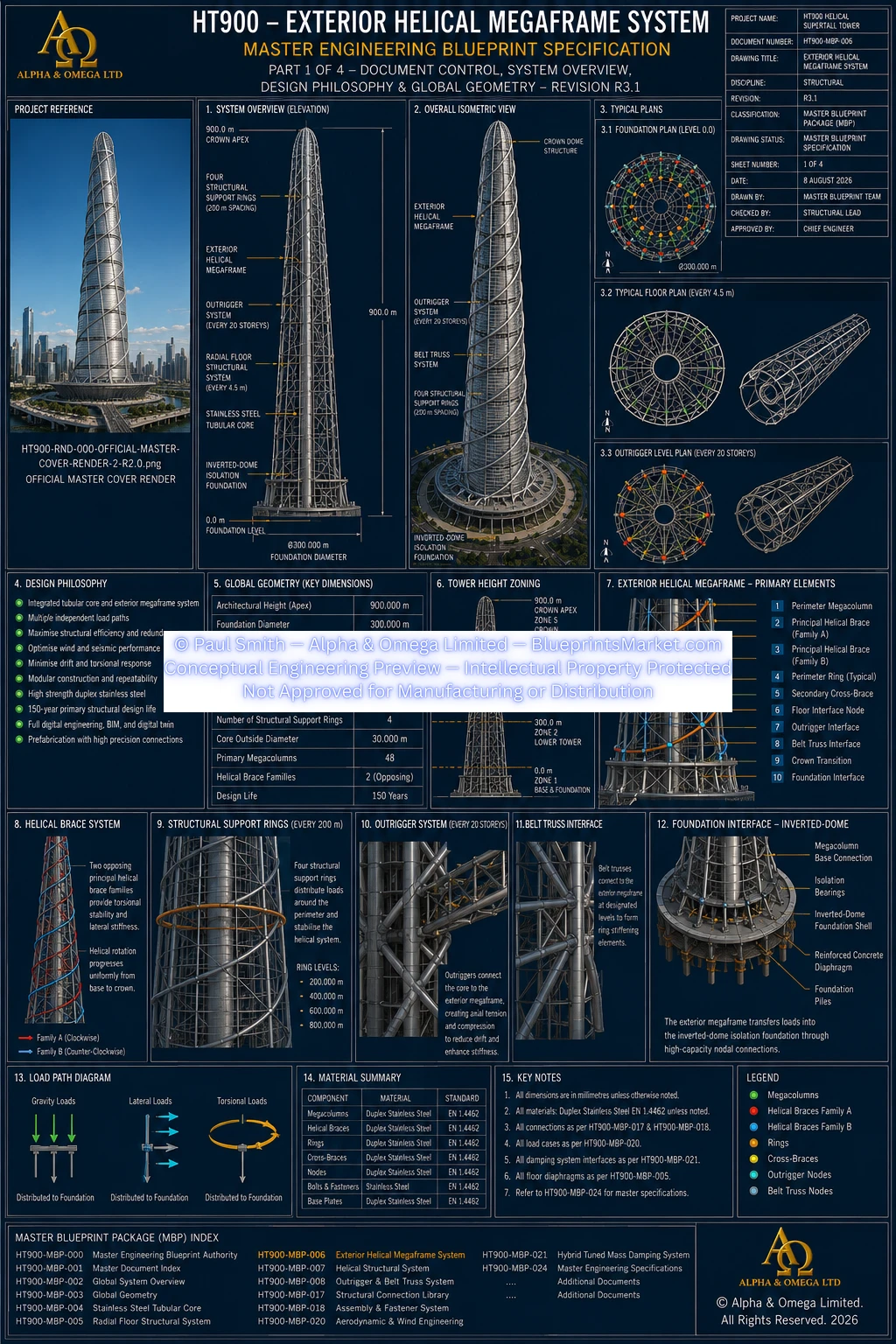
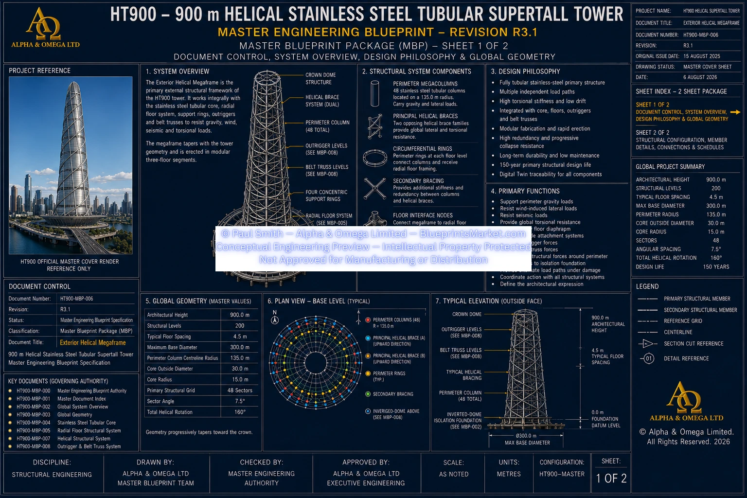
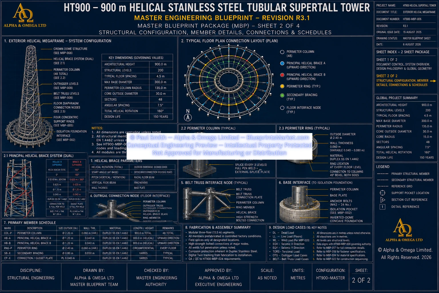
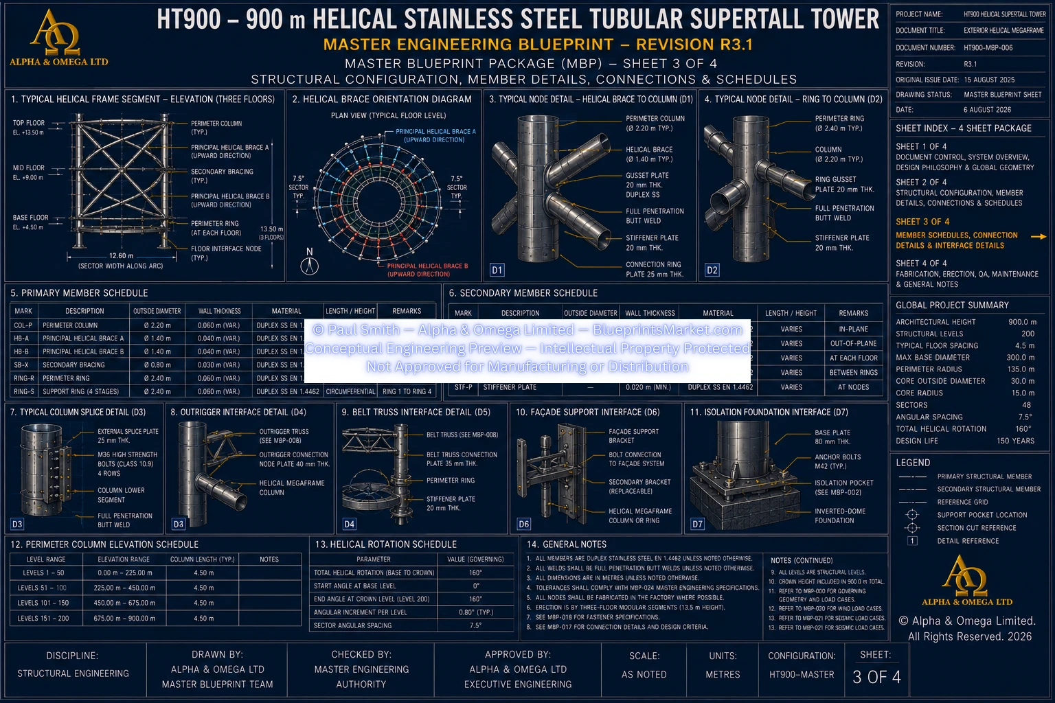
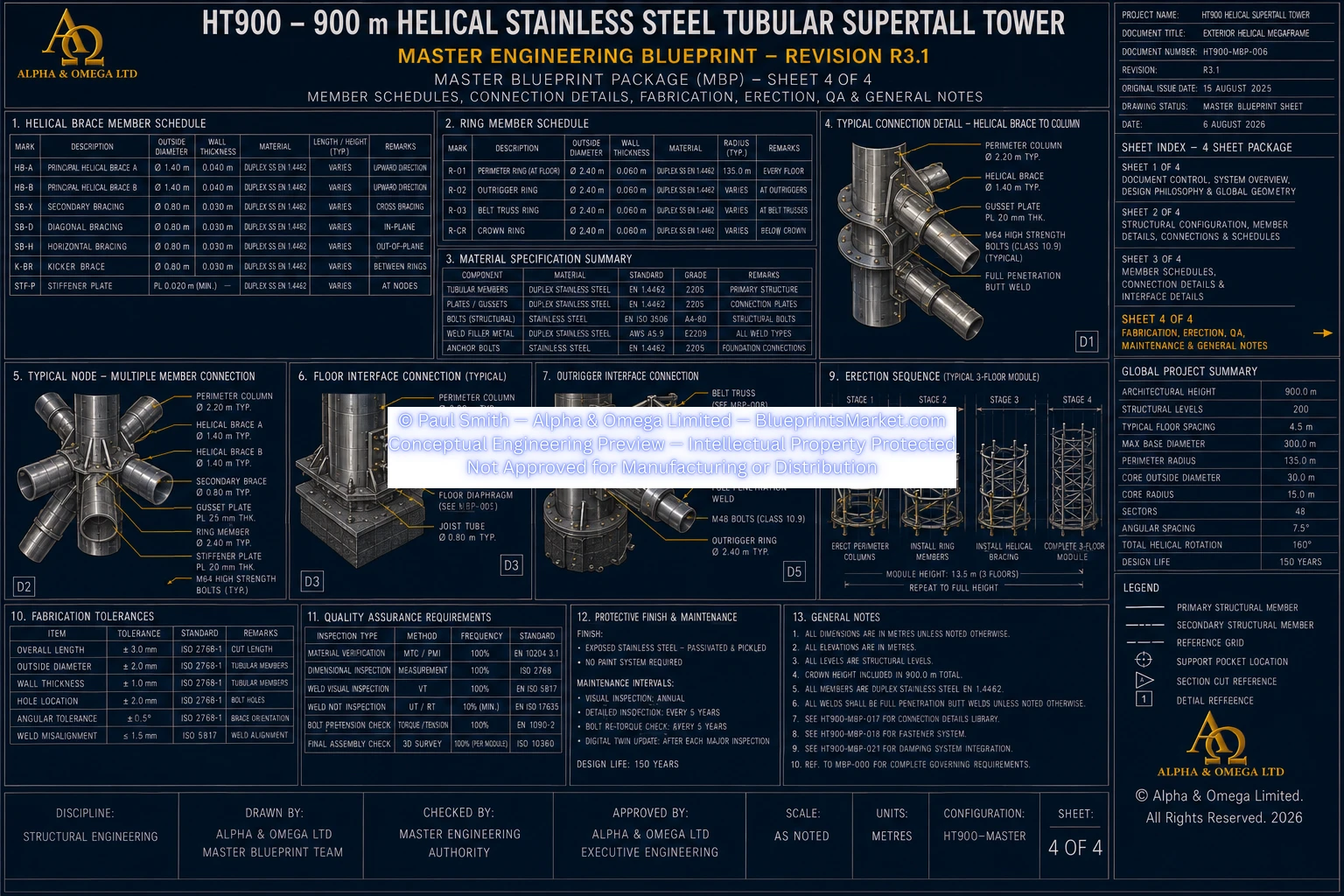
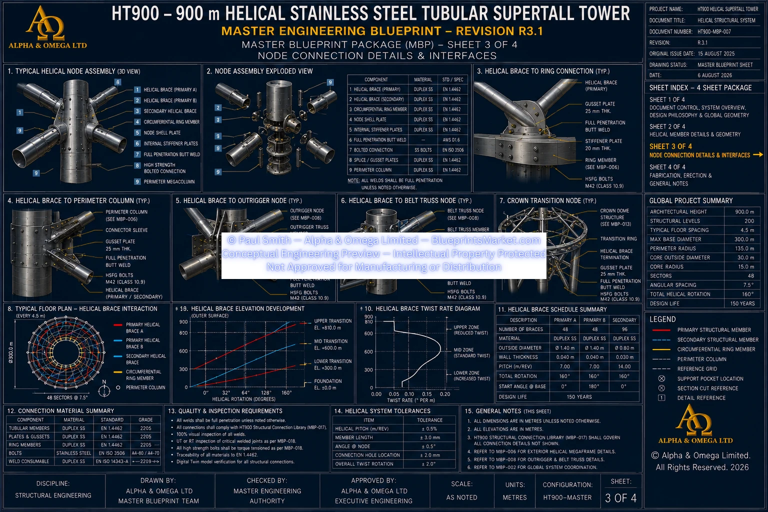
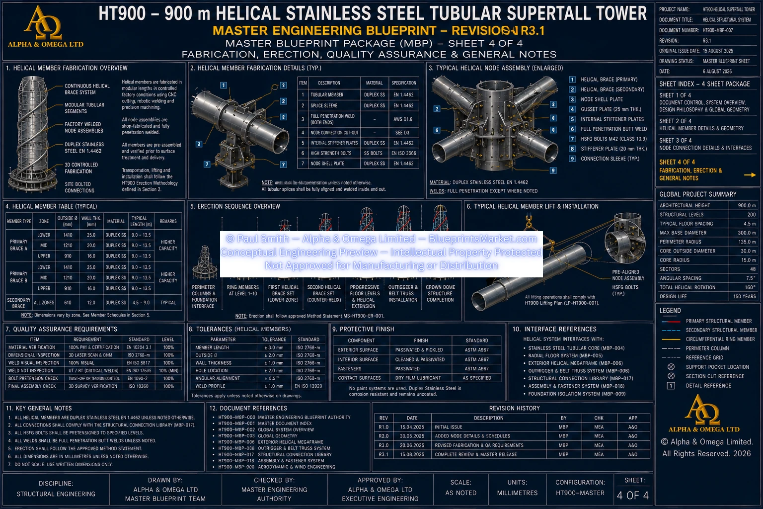
HT900-MBP-006 — EXTERIOR HELICAL MEGA FRAME
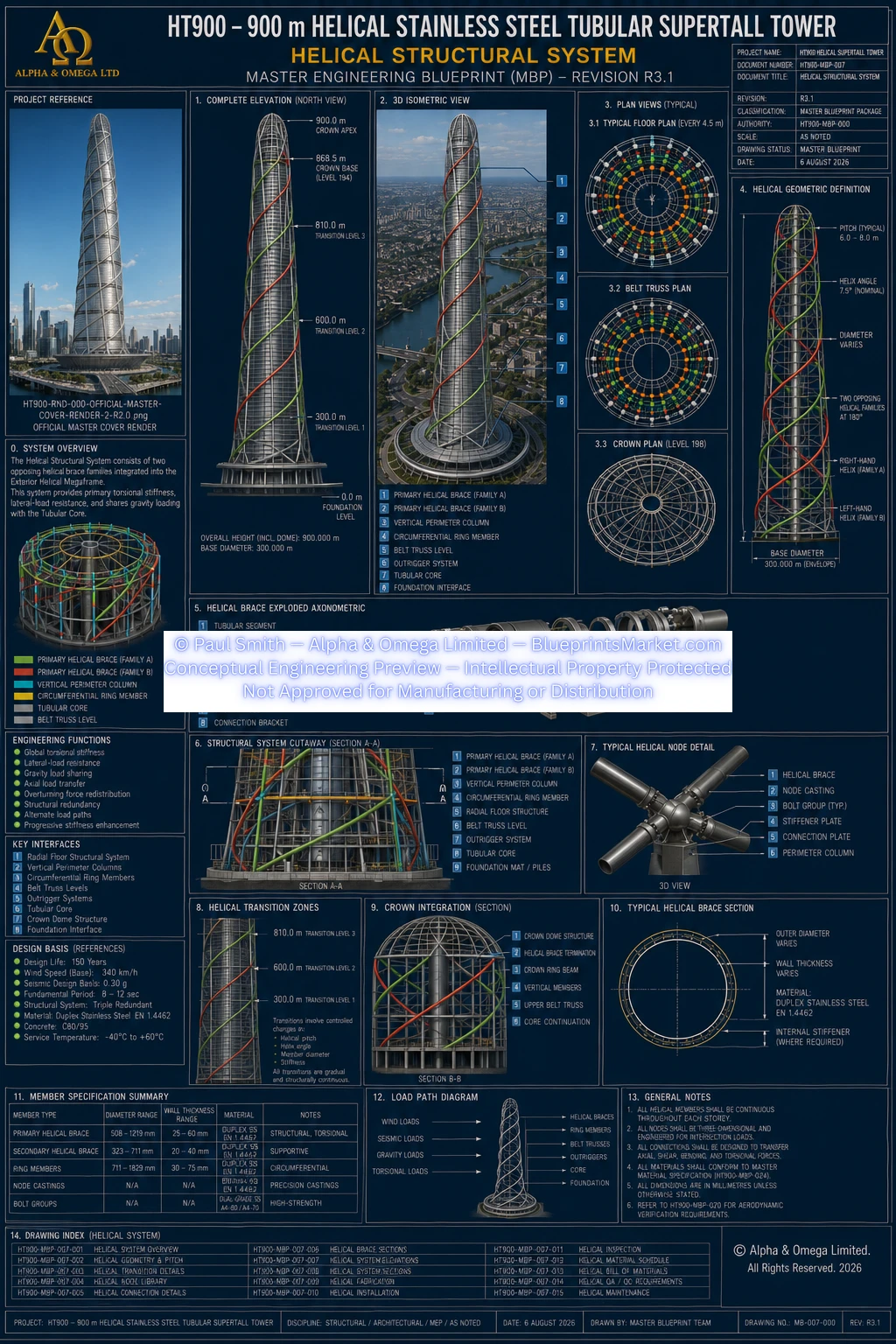
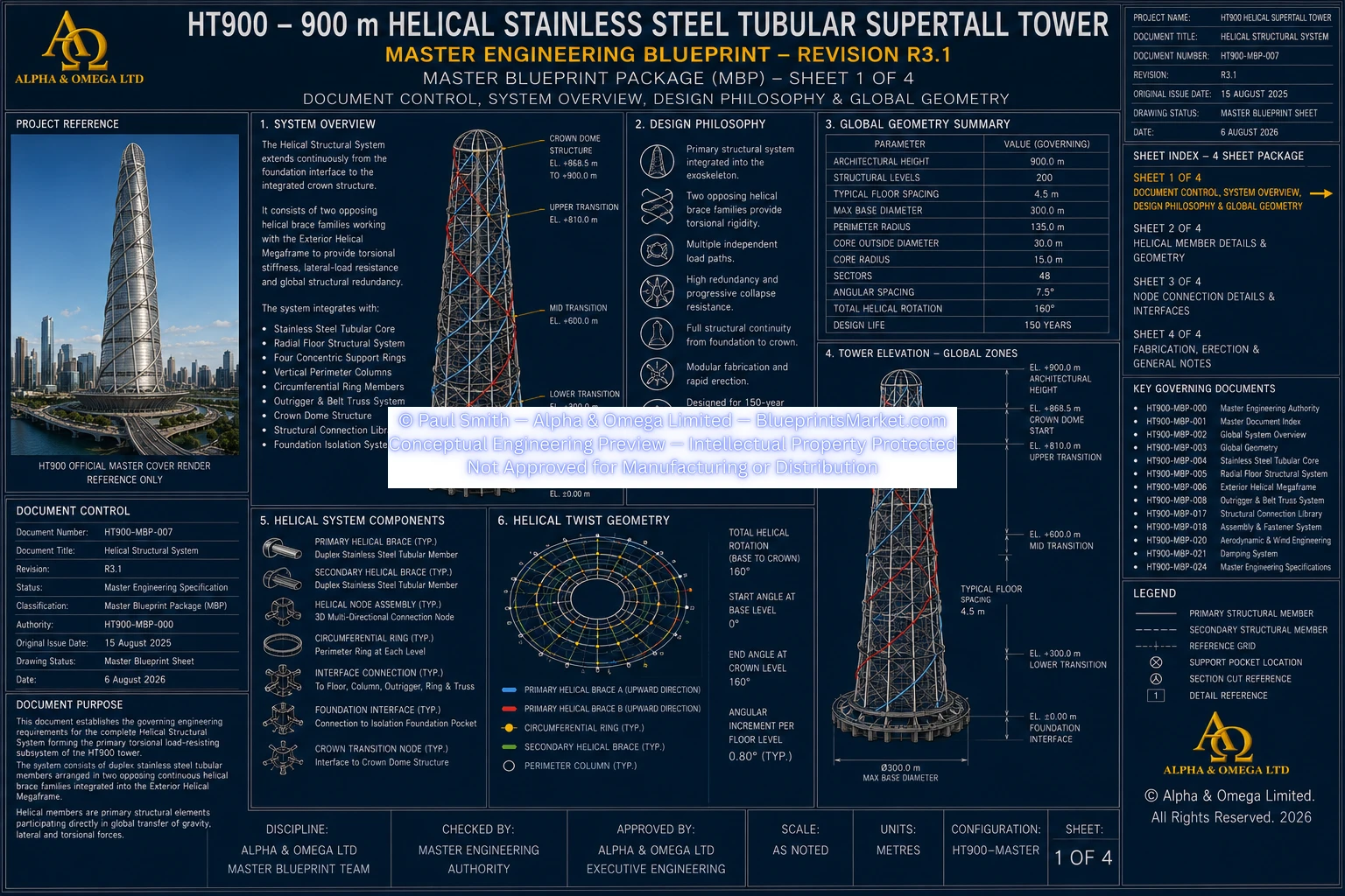
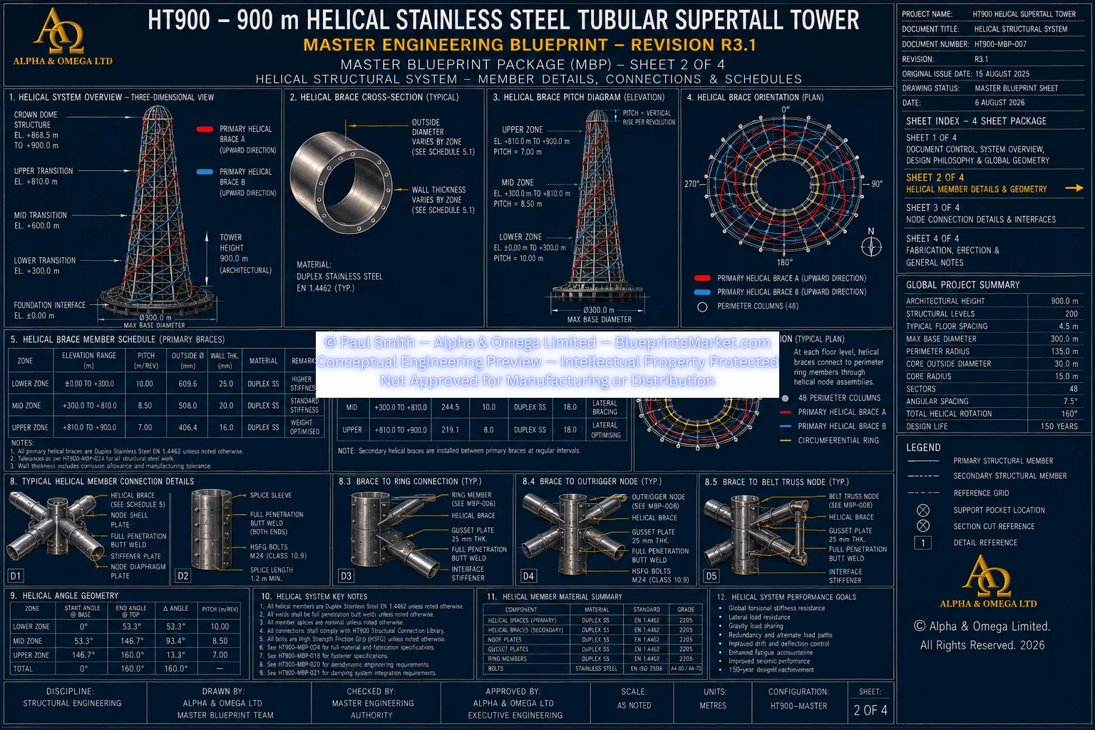
HT900-MBP-007 — HELICAL STRUCTURAL SYSTEM
Copyright — Alpha & Omega Limited
All blueprint files, CAD parameters, architectural concepts, engineering specifications, and written content are the exclusive intellectual property of Alpha & Omega Limited. No part of the Stainless‑Steel Skyscraper Blueprint Package may be reproduced, distributed, or adapted without written consent.
Licensing, Copyright & Patent Restrictions
This engineering system and all associated blueprint materials, CAD files, diagrams, schematics, dimensional tables, and technical narratives are licensed, not sold, and remain the exclusive intellectual property of Alpha & Omega Limited.
This product is not eligible for patenting by any purchaser, user, organization, or third party. Patent filings, provisional patents, utility models, derivative patents, reverse‑engineering for patent purposes, and intellectual property claims are strictly prohibited.
Redistribution, resale, sublicensing, public posting, dataset inclusion, or any form of unauthorized duplication of blueprint materials, CAD files, diagrams, or engineering concepts is strictly prohibited. No license tier grants ownership, patent rights, or rights to file for intellectual property protection.
All architectural & engineering systems are conceptual and require full professional engineering validation before any real‑world use, construction, prototyping, or structural implementation.
Full legal details are available in the Terms & Conditions .