
Radial Floor Truss & Ring Beam System
HT900 — Tubular Stainless-Steel Radial Floor Framing, Concentric Ring Support & Composite Diaphragm System
1.0 System Overview
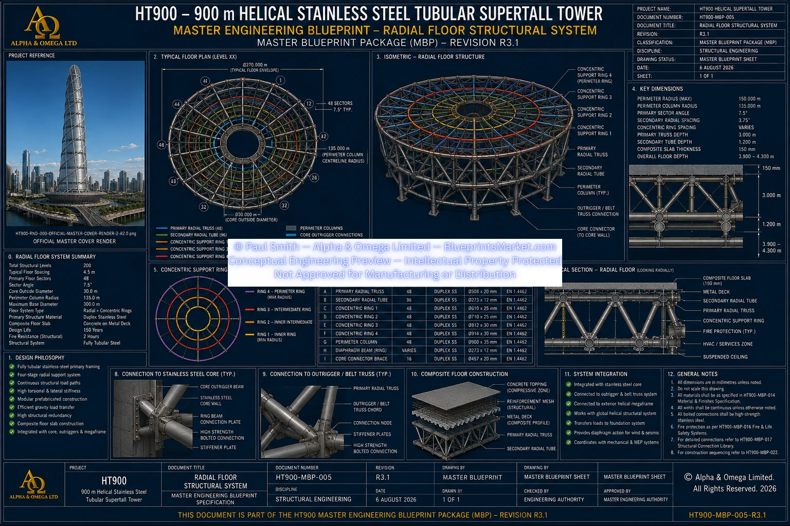
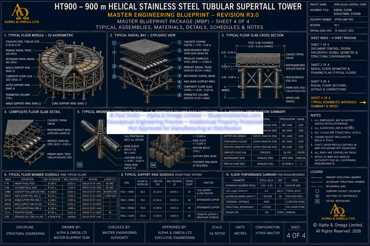
The HT900 Radial Floor Truss & Ring Beam System forms the principal horizontal structural framework of the 900-metre Helical Stainless-Steel Tubular Supertall Tower.
The system connects the 30-metre-diameter Stainless-Steel Tubular Core with the Exterior Helical Megaframe through a coordinated network of radial tubular framing, concentric structural support rings, secondary floor framing and composite floor construction.
The primary floor framing is constructed entirely from Duplex Stainless Steel tubular structural members. Concrete is used within the composite structural floor slab and does not form the tower's primary floor framing.
2.0 Primary Structural Functions
The radial floor and ring-beam architecture performs several structural functions simultaneously.
Gravity-Load Functions
- Supports permanent building loads
- Supports imposed floor loads
- Supports architectural floor construction
- Supports plant and equipment loads
- Distributes façade reactions where applicable
- Transfers gravity forces toward the core and perimeter structure
Lateral-Load Functions
- Transfers wind-induced diaphragm shear
- Transfers seismic diaphragm forces
- Connects the tubular core with the perimeter structure
- Redistributes torsional loading
- Transfers forces into the Outrigger & Belt Truss System
Structural-Stability Functions
- Restrains radial spreading
- Provides circumferential load redistribution
- Provides alternative structural load paths
- Improves progressive-collapse resistance
- Coordinates with the helical structural system
- Improves global torsional stiffness
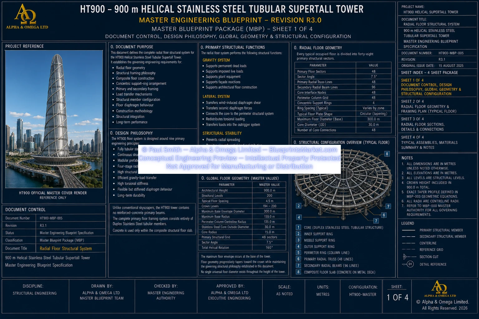
3.0 Governing Floor Geometry
| Architectural Height | 900 m |
|---|---|
| Structural Levels | 200 |
| Typical Floor Spacing | 4.5 m |
| Maximum Base Envelope Diameter | 300 m |
| Maximum Base Radius | 150 m |
| Perimeter Structural Radius | 135 m |
| Tubular Stainless-Steel Core Diameter | 30 m |
| Primary Structural Grid | 48 sectors |
| Sector Angle | 7.5° |
| Total Helical Rotation | 160° |
The maximum floor envelope occurs toward the base of the tower. Floor geometry progressively tapers toward the crown and therefore does not use one constant diameter throughout the full 900-metre height.
4.0 Radial Structural Grid
Every typical occupied floor is divided into 48 primary structural sectors.
| Primary Floor Sectors | 48 |
|---|---|
| Sector Angle | 7.5° |
| Primary Radial Truss Lines | 48 |
| Secondary Radial Beam Lines | 96 |
| Core Interface Nodes | 48 |
| Perimeter Interface Nodes | 48 |
Each structural sector is designed as a modular assembly while remaining fully integrated into the completed floor diaphragm.
Complete structural floors are not intended to be fabricated, transported or lifted as single assemblies.
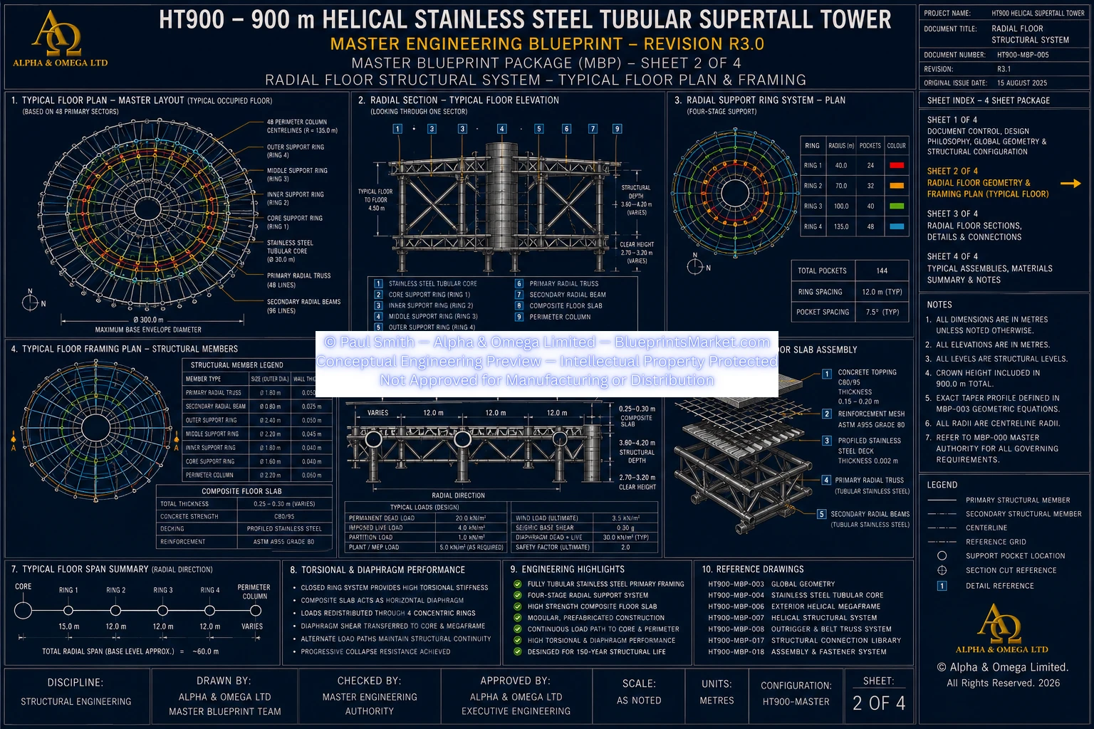
5.0 Concentric Structural Ring System
The current HT900 floor structure does not rely upon one uninterrupted radial span between the core and perimeter.
Instead, a hierarchy of four principal concentric structural support rings divides the floor structure into efficient radial bays.
| Core Interface | 15 m radius |
|---|---|
| Structural Ring R1 | 45 m radius |
| Structural Ring R2 | 75 m radius |
| Structural Ring R3 | 105 m radius |
| Perimeter Ring R4 | 135 m radius |
This arrangement creates typical radial structural bays of approximately 30 metres, avoiding the unrealistic very-long unsupported radial spans used in earlier concepts.
6.0 Ring Beam Structural Functions
The concentric ring beams form continuous circumferential structural members around the tower.
Their principal functions include:
- Maintaining circular floor geometry
- Providing radial restraint
- Providing circumferential stiffness
- Resisting circumferential tension and compression
- Preventing radial spreading
- Redistributing gravity loads
- Redistributing lateral forces
- Improving torsional stability
- Improving structural redundancy
- Supporting progressive-collapse resistance
- Providing construction-stage structural support
7.0 Seven-Zone Floor Structural Configuration
Each typical structural floor is organised into seven coordinated structural zones.
Zone 1 — Core Interface
The radial floor system begins at the 30-metre-diameter tubular stainless-steel core.
This interface forms a major transfer zone for gravity, torsional and lateral structural forces.
Zone 2 — Inner Radial Structural Bay
The first radial structural bay extends between the core interface and Structural Ring R1.
Its principal functions include gravity-load transfer, diaphragm action, torsional restraint and service support.
Zone 3 — Intermediate Radial Bays
Intermediate structural bays extend between Rings R1 and R2 and between Rings R2 and R3.
These bays reduce effective member lengths while improving stiffness, vibration behaviour and structural redundancy.
Zone 4 — Outer Radial Bay
The outer radial bay extends between Ring R3 and the Perimeter Ring R4.
This zone transfers structural forces directly into the Exterior Helical Megaframe.
Zone 5 — Secondary Floor Framing
Secondary tubular framing spans between adjacent primary radial structural lines.
It supports the composite floor deck, local loads, architectural construction and coordinated service penetrations.
Zone 6 — Circumferential Ring Beam System
The concentric ring system provides circumferential stiffness, radial restraint, structural continuity and alternative load-transfer paths.
Zone 7 — Exterior Megaframe Interface
Every primary radial structural line terminates at the perimeter structural system through engineered stainless-steel structural interfaces.
This creates the principal floor-level connection between the composite diaphragm and the tower's global lateral-resisting structural system.
8.0 Primary Radial Truss System
The 48 primary radial tubular trusses form the principal gravity-load-carrying framework of each typical structural floor.
Rather than spanning directly from the core to the perimeter, each truss line is supported through the concentric ring hierarchy.
Primary Functions
- Transfer gravity loads
- Support the composite floor diaphragm
- Support the concentric ring system
- Provide torsional restraint
- Improve progressive-collapse resistance
- Provide structural redundancy
- Integrate the core with the perimeter structural system
Structural member sizing is progressively optimised through the tower height according to changing gravity, wind, seismic, dynamic and structural demands.
9.0 Secondary Tubular Floor Framing
Secondary Duplex Stainless-Steel framing spans between adjacent primary radial structural lines.
Its functions include:
- Supporting the composite floor deck
- Reducing local deck spans
- Distributing local floor loading
- Supporting coordinated service penetrations
- Improving vibration behaviour
- Supporting architectural floor construction
10.0 Diagonal Floor Bracing
Tubular diagonal floor bracing may be incorporated where required by structural analysis to increase local and global diaphragm performance.
Diagonal bracing may assist with:
- In-plane diaphragm stiffness
- Local stability
- Torsional stiffness
- Structural redundancy
- Vibration control
- Alternative load paths
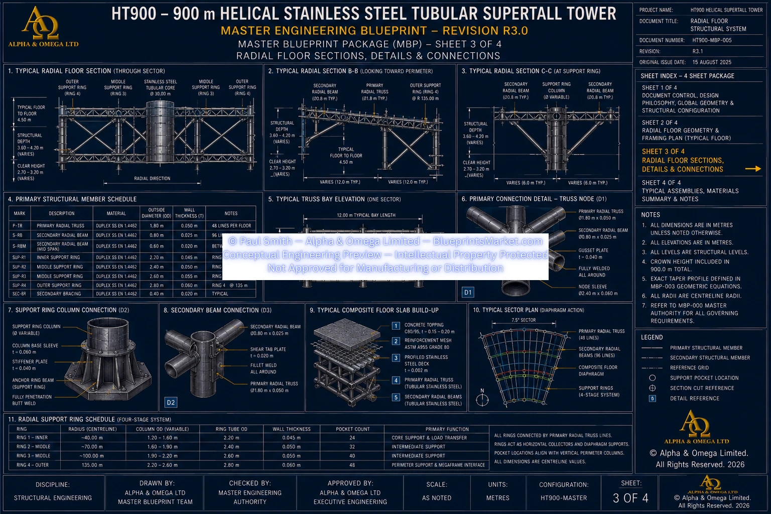
11.0 Structural Node Architecture
Engineered stainless-steel structural nodes coordinate the multiple structural systems meeting at each floor.
Node interfaces may connect:
- Primary radial trusses
- Secondary tubular framing
- Concentric ring beams
- Perimeter megacolumns
- Helical structural members
- Outrigger interfaces
- Belt-truss interfaces
- Façade support systems
The node architecture provides three-dimensional transfer of axial, shear, bending and torsional forces throughout the floor structure.
12.0 Composite Floor Construction
The tubular stainless-steel floor framework supports an integrated composite structural floor assembly.
The complete floor construction incorporates:
- Stainless-steel profiled structural decking
- Composite shear-transfer system
- Lightweight reinforced-concrete structural topping
- Acoustic isolation systems
- Raised service floors where required
- Architectural finishes
The composite slab contributes to diaphragm stiffness, vibration control, acoustic performance, fire performance and service integration.
The concrete slab is not part of the primary load-carrying frame. The principal floor structure remains tubular stainless steel.
13.0 Floor Diaphragm Behaviour
The current HT900 structural baseline defines each completed floor as a flexible but highly stiffened composite diaphragm.
The floor is not assumed to behave as a perfectly rigid plate.
Diaphragm Functions
- Transfer in-plane structural shear
- Distribute torsional forces
- Balance gravity reactions
- Coordinate movement between core and perimeter
- Redistribute forces following local structural damage
- Maintain continuity during extreme loading
The floor diaphragm works together with the tubular core, exterior megaframe, ring beams, outriggers, belt trusses and helical structural system.
14.0 Gravity Load Path
Gravity loading is distributed through the composite floor construction into the tubular stainless-steel structural framing.
The conceptual load path is:
Occupancy & Equipment → Composite Floor → Stainless-Steel Deck → Secondary Framing → Primary Radial Trusses → Concentric Structural Rings → Tubular Core & Exterior Megaframe → Foundation System
15.0 Wind Load Path
Wind forces acting upon the façade are transferred into the Exterior Helical Megaframe and then distributed through the floor and global structural systems.
The conceptual load path is:
Façade → Façade Support System → Exterior Helical Megaframe → Perimeter Ring R4 → Concentric Ring System → Floor Diaphragm → Outriggers → Tubular Core → Foundation
16.0 Seismic Load Integration
Seismic movement enters the tower through the deep foundation and seismic-isolation architecture before being distributed into the superstructure.
Above the isolation system, the radial floor diaphragms provide an important mechanism for distributing seismic actions between the tubular core, concentric rings and exterior megaframe.
This helps create multiple alternative load paths rather than concentrating seismic response in one structural component.
17.0 Torsional Stability
Torsional performance is especially important because the HT900 uses a helical exterior structural form.
Torsional forces are redistributed through:
- Exterior Helical Megaframe
- Perimeter megacolumns
- Perimeter Ring R4
- Intermediate concentric rings
- Radial tubular trusses
- Composite floor diaphragm
- Tubular stainless-steel core
Together these systems create a closed three-dimensional structural network capable of transferring torsional forces through multiple paths.
18.0 Structural Redundancy
Redundancy is a fundamental part of the HT900 floor-system philosophy.
Multiple load paths are provided through:
- 48 radial structural sectors
- Four concentric structural support rings
- Continuous circumferential ring members
- Composite diaphragm action
- Exterior Helical Megaframe
- Tubular Stainless-Steel Core
- Outrigger system
- Belt-truss system
- Helical structural members
- Three-dimensional structural node assemblies
No single principal floor member is intended to function as the sole structural load path for the complete floor system.
19.0 Structural Performance Objectives
The current conceptual engineering baseline establishes structural-performance objectives including:
| Typical Floor Deflection Target | L/500 |
|---|---|
| Sensitive Equipment Areas | L/750 |
| Vibration Performance | ISO 10137 or equivalent project criterion |
| Progressive Collapse Strategy | Alternative load-path design |
| Fire Performance | Project-specific fire strategy |
| Primary Structural Design Life | 150 years |
Final performance requires project-specific structural analysis, dynamic analysis, wind engineering and detailed verification.
20.0 Structural Material Philosophy
| Primary Floor Framing | Duplex Stainless Steel EN 1.4462 |
|---|---|
| Primary Structural Form | Tubular Stainless-Steel Framing |
| Secondary Structural Components | Compatible Stainless-Steel Systems |
| Composite Floor Component | Lightweight Reinforced Structural Concrete |
| Higher-Demand Components | Higher-performance stainless-steel grades where detailed engineering requires |
Reinforced concrete is limited to approved composite floor construction and does not replace the tubular stainless-steel primary framing system.
21.0 Modular Fabrication & Construction
The floor system is designed around controlled factory prefabrication and modular site assembly.
Typical structural modules may include:
- Radial truss assemblies
- Ring-beam segments
- Secondary tubular framing modules
- Structural node assemblies
- Deck-support modules
Modular construction improves fabrication quality, dimensional consistency, inspection, transportability and construction sequencing.
Entire floors are not fabricated, transported or lifted as single structural assemblies.
22.0 Structural Health Monitoring
The radial floor system forms an integral part of the HT900 Structural Health Monitoring and Digital Twin architecture.
Monitoring may incorporate:
- Strain monitoring
- Fibre-optic sensing
- Acceleration monitoring
- Deflection monitoring
- Temperature monitoring
- Vibration monitoring
- Displacement monitoring
- Long-term structural movement records
Digital asset records can maintain manufacturing, inspection, maintenance and structural-condition information throughout the building lifecycle.
23.0 Inspection & Lifecycle Strategy
Structural floors are designed to permit long-term inspection and monitoring without compromising the integrity of the primary structural framing.
Inspection coverage includes:
- Primary radial trusses
- Secondary floor framing
- Concentric structural rings
- Structural node assemblies
- Core interfaces
- Perimeter interfaces
- Composite floor inspection points
- Movement joints
- Structural monitoring equipment
Replaceable architectural and building-service components are designed so that maintenance or renewal does not require modification of the primary floor structure.
24.0 Tower-Wide Structural Integration
The Radial Floor Truss & Ring Beam System interfaces directly with:
- Stainless-Steel Tubular Core
- Exterior Helical Megaframe
- Helical Structural System
- Outrigger & Belt Truss System
- Crown Dome Structure
- Structural Connection System
- Assembly & Fastener System
- Exterior Façade Support System
- MEP Services
- Fire & Life Safety Systems
- Structural Health Monitoring
- Digital Twin Infrastructure
This integration allows each structural floor to participate in the complete three-dimensional load-resisting architecture of the tower.
25.0 Engineering Summary
The HT900 Radial Floor Truss & Ring Beam System provides the principal horizontal structural connection between the 30-metre Tubular Stainless-Steel Core and the Exterior Helical Megaframe.
The current system uses 48 radial structural sectors at 7.5° spacing together with four concentric structural support rings extending from the core interface to the 135-metre perimeter structural radius.
This creates a sequence of efficient structural bays of approximately 30 metres rather than relying upon unsupported radial spans exceeding 100 metres.
Each completed floor acts as a flexible but highly stiffened composite diaphragm integrated with the tubular core, ring system, exterior megaframe, helical structure, outriggers and belt trusses.
Together these systems provide redundant gravity, wind, seismic and torsional load paths extending from the occupied floors through the complete superstructure to the foundation and seismic-isolation system.
26.0 Conceptual Engineering Notice
This public page presents the high-level structural architecture and engineering philosophy of the HT900 Radial Floor Truss & Ring Beam System.
Detailed tube diameters, wall-thickness schedules, structural node geometry, weld specifications, fastener schedules, composite slab reinforcement, connection details, fabrication tolerances, erection tolerances, inspection schedules and other implementation-level engineering information are contained within the licensed HT900 Master Blueprint Package and are intentionally not reproduced on this public overview page.
Any real-world implementation would require complete project-specific structural analysis, floor-vibration analysis, progressive-collapse assessment, connection engineering, fire engineering, fabrication design, coordinated BIM modelling, construction-stage analysis, regulatory approval and certification by appropriately qualified and licensed engineering professionals.
HT900-MBP-005 — RADIAL FLOOR TRUSS & RING BEAM SYSTEM
Copyright — Alpha & Omega Limited
All blueprint files, CAD parameters, architectural concepts, engineering specifications, and written content are the exclusive intellectual property of Alpha & Omega Limited. No part of the Stainless‑Steel Skyscraper Blueprint Package may be reproduced, distributed, or adapted without written consent.
Licensing, Copyright & Patent Restrictions
This engineering system and all associated blueprint materials, CAD files, diagrams, schematics, dimensional tables, and technical narratives are licensed, not sold, and remain the exclusive intellectual property of Alpha & Omega Limited.
This product is not eligible for patenting by any purchaser, user, organization, or third party. Patent filings, provisional patents, utility models, derivative patents, reverse‑engineering for patent purposes, and intellectual property claims are strictly prohibited.
Redistribution, resale, sublicensing, public posting, dataset inclusion, or any form of unauthorized duplication of blueprint materials, CAD files, diagrams, or engineering concepts is strictly prohibited. No license tier grants ownership, patent rights, or rights to file for intellectual property protection.
All architectural & engineering systems are conceptual and require full professional engineering validation before any real‑world use, construction, prototyping, or structural implementation.
Full legal details are available in the Terms & Conditions .