
Maintenance & Access Systems
HT900 — Integrated Inspection, Façade Access, Component Replacement, Rescue & Lifecycle Maintenance Architecture
1.0 System Overview
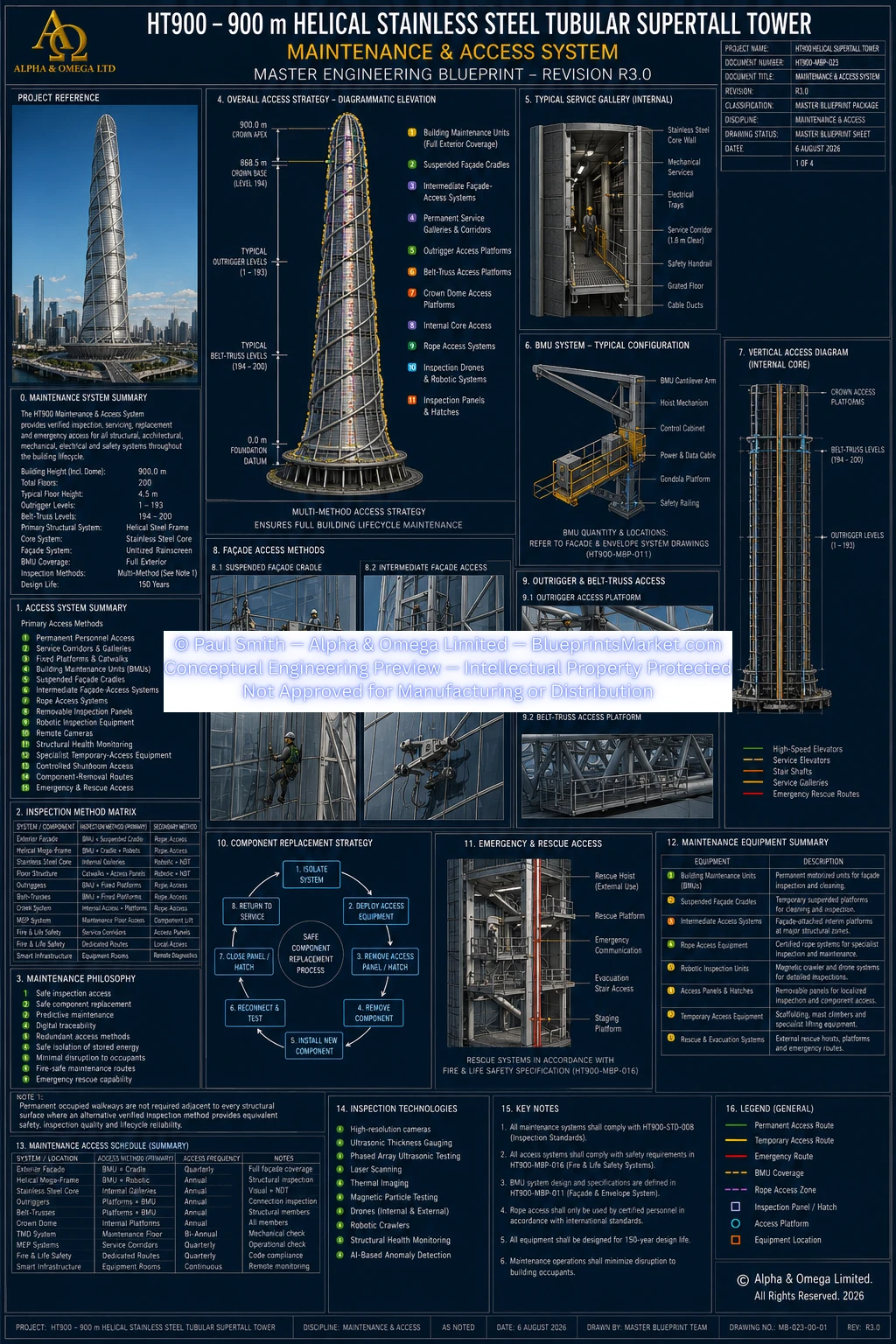
The HT900 Maintenance & Access System provides the coordinated infrastructure required to inspect, maintain, service, repair and replace major systems throughout the operational life of the 900-metre Helical Stainless-Steel Tubular Supertall Tower.
The system combines permanent access infrastructure with deployable and remote inspection technologies so that each major structural, architectural, mechanical, electrical, life-safety and digital system has an appropriate inspection and maintenance method.
The current HT900 philosophy does not require a permanently occupied walkway beside every structural surface. Instead, it requires verified inspection-method coverage using the most appropriate access method for each location.
2.0 Maintenance Engineering Philosophy
The HT900 maintenance architecture is based on ten principal engineering objectives:
- Safe inspection access
- Safe component replacement
- Predictive maintenance
- Digital traceability
- Redundant access methods
- Safe isolation of stored energy
- Minimal disruption to occupants
- Fire-safe maintenance routes
- Emergency rescue capability
- Long-term adaptability
Permanent structural infrastructure is coordinated with the HT900 150-year primary structural design-life philosophy, while mechanical, electrical, façade, hydraulic, electronic, control and other operational systems are treated as maintainable and replaceable assets with shorter service cycles.
3.0 Verified Inspection-Method Architecture
Inspection and maintenance access may be provided through a coordinated combination of:
- Permanent personnel access
- Dedicated service corridors
- Structural inspection galleries
- Fixed maintenance platforms
- Catwalks and service bridges
- Building Maintenance Units
- Suspended façade cradles
- Intermediate façade-access systems
- Rope-access systems
- Removable inspection panels
- Remote inspection cameras
- Robotic inspection equipment
- Structural Health Monitoring
- Specialist temporary-access systems
- Controlled shutdown access
- Component-removal routes
- Emergency and rescue access
Every primary structural system is intended to have an approved inspection methodology, whether through direct access, remote inspection, permanent sensing or a combination of methods.
4.0 Building Systems Covered
The Maintenance & Access System extends across the complete HT900 engineering architecture.
- Exterior cladding and curtain-wall system
- Exterior Helical Megaframe
- 30-metre tubular stainless-steel structural core
- Radial Floor Structural System
- Concentric structural rings
- Outrigger systems
- Belt-truss systems
- Structural connection nodes
- Crown Dome Structure
- Hybrid Tuned Mass Damping System
- Vertical Transportation
- Mechanical and HVAC systems
- Electrical systems
- Hydraulic and plumbing systems
- Fire & Life Safety systems
- Building Control systems
- Smart Infrastructure
- Structural Health Monitoring
- Wind-monitoring equipment
- Foundation and seismic-isolation system
- Communications infrastructure
- Lightning-protection systems
5.0 Exterior Façade Access System
The HT900 façade-access strategy is designed around a combination of complementary systems rather than requiring one access method to serve every part of the tower.
Exterior access may incorporate:
- Crown-mounted Building Maintenance Units
- Intermediate Building Maintenance Units
- Suspended maintenance cradles
- Façade restraint anchors
- Docking points
- Rope-guide systems
- Setback access platforms
- Rope-access anchor networks
- Local monorail systems
- Specialist temporary-access systems
The project target is 100% maintainable façade coverage. This means every façade zone must have an approved method for inspection, cleaning, repair and component replacement.
Coverage is verified through three-dimensional reach analysis, cradle-path studies, blind-zone mapping, setback studies, clash detection and façade-component replacement analysis.
6.0 Building Maintenance Units
Multiple Building Maintenance Units are integrated with the Crown Dome and selected intermediate tower levels to provide mechanised exterior access.
Principal BMU systems may incorporate:
- Rotating turret assemblies
- Telescopic or variable-outreach jibs
- Powered suspended cradles
- Programmable motion controls
- Automatic parking systems
- Emergency manual recovery
- Load monitoring
- Rope-tension monitoring
- Wind monitoring
- Anti-collision systems
- Track-position monitoring
- Independent emergency communications
Final BMU quantity, location and reach are determined by the coordinated façade-access study rather than being fixed as one universal arrangement.
7.0 BMU Safety & Long-Drop Engineering
Exterior access at the scale of a 900-metre tower requires specialised long-drop engineering.
Relevant engineering considerations include:
- Suspension-rope self-weight
- Rope elongation
- Rope oscillation
- Wind-gradient effects
- Vortex-induced rope movement
- Cradle stabilisation
- Façade restraint-anchor interaction
- Emergency retrieval
- Long-duration ascent and descent
- Technician rescue from intermediate elevations
- Inspection and replacement of suspension systems
BMU operating limits and secured storm-survival requirements are project-specific and would be verified using equipment certification, aerodynamic analysis and wind-tunnel-derived crown conditions.
8.0 Exterior Access Safety Systems
Suspended access systems incorporate multiple independent safety provisions.
- Dual suspension systems
- Independent safety ropes
- Automatic overspeed arrest
- Redundant braking
- Load monitoring
- Rope-tension monitoring
- Slack-rope detection
- Emergency descent
- Manual recovery
- Wind lockout
- Lightning shutdown
- Seismic lockout
- Overload protection
- Anti-collision systems
- Emergency-stop systems
- Storm-parking systems
Certified local machinery safety controls remain independent of the general Building Management System and Digital Twin.
9.0 Crown Maintenance Access
The Crown Access System is integrated into the tapered elongated helical Crown Dome occupying Levels 194–200.
| Crown Base Elevation | Approximately 868.5 m |
|---|---|
| Apex Elevation | 900 m |
| Approximate Crown Structural Height | 31.5 m |
| Approximate Crown Base Diameter | 60 m |
Crown access systems may include:
- Stainless-steel maintenance catwalks
- Helical inspection paths
- Ring-level platforms
- Structural rib access
- BMU service bays
- Communications-equipment access
- Lightning-protection access
- HTMD maintenance access
- Inspection hatches
- Rescue davits
- Maintenance lifting beams
- Service monorails
10.0 Structural Inspection System
Structural inspection is coordinated with the complete tubular stainless-steel structural system.
Inspection provisions cover:
- Tubular core shell
- Core diaphragm systems
- Vertical stiffeners
- Radial structural framing
- Concentric structural rings
- Perimeter megacolumns
- Helical structural members
- Outrigger nodes
- Belt-truss nodes
- Crown structural members
- HTMD support structure
- Foundation support interfaces
- Façade support interfaces
Inspection methods may combine direct personnel access, remote cameras, robotic systems, laser scanning, non-destructive examination and permanent structural sensors.
11.0 Tubular Core Access System
The HT900 central core is a 30-metre-diameter continuous circular Duplex Stainless-Steel structural shell.
It does not contain a reinforced-concrete primary structural core.
Maintenance access within and around the core supports:
- Core shell inspection
- Structural weld inspection
- Ring-diaphragm inspection
- Vertical-stiffener inspection
- Elevator and guide-system maintenance
- Protected stair systems
- Mechanical risers
- Electrical risers
- Fire services
- Water and drainage systems
- Communications infrastructure
- Structural monitoring equipment
Routine heavy-equipment movement uses dedicated service routes rather than relying on protected emergency stairs.
12.0 Internal Service Corridors & Equipment Routes
Dedicated internal service corridors provide protected access to building plant, utilities and maintenance areas while reducing interaction with occupied public zones.
These routes may serve:
- Mechanical rooms
- Electrical rooms
- Pump rooms
- Communications rooms
- Building-control equipment
- Fire systems
- Water services
- Structural-monitoring systems
- Elevator equipment
- Equipment replacement routes
- Maintenance storage
Replacement routes are coordinated for equipment dimensions, turning clearance, lifting requirements, floor capacity, temporary storage and fire-safety separation.
13.0 Foundation & Isolation-System Access
Maintenance infrastructure extends into the 300-metre inverted-dome foundation and the complete seismic-isolation system.
The current HT900 baseline includes:
- 144 seismic-isolation pocket assemblies
- 144 associated foundation support groups
- 1,152 deep foundation piles
- Foundation drainage and waterproofing systems
- Structural monitoring and instrumentation
Foundation access may use local access chambers, inspection galleries, connecting corridors, removable panels, controlled-entry routes and specialist confined-space access.
A continuous occupied tunnel around the entire foundation is not established as a universal requirement.
14.0 Stored-Energy Control
Maintenance of the isolation system, Hybrid Tuned Mass Damper, suspended-access equipment and other dynamic systems may involve significant stored mechanical, hydraulic or electrical energy.
Safe maintenance requires controlled procedures including:
- Lockout and tagout
- Verified zero-energy state
- Mechanical restraint
- Hydraulic isolation
- Electrical isolation
- Temporary structural support where required
- Permit-to-work procedures
- Engineering approval for critical work
Personnel access to controlled movement zones is permitted only after applicable energy sources have been safely isolated and restrained.
15.0 Hybrid Tuned Mass Damper Access
The HT900 Hybrid Tuned Mass Damper occupies the upper-tower and integrated crown zone and requires dedicated inspection, servicing and heavy-maintenance provisions.
Access infrastructure supports inspection and replacement of:
- Primary damping-mass systems
- Support framing
- Bearings and guides
- Hydraulic damping equipment
- Active control equipment
- Position and load sensors
- Control cabinets
- Emergency restraints
- Structural monitoring systems
Entry into dynamic movement zones requires confirmed maintenance mode and mechanical restraint.
16.0 Component Replacement Strategy
Maintainability is not limited to inspection. The HT900 also provides defined replacement routes for major operational equipment and building-envelope components.
Replaceable systems include:
- BMU machinery
- Hoist systems
- Suspension systems
- Damping equipment
- Bearings
- Sensors
- Control cabinets
- Communications equipment
- Electrical switchgear
- Pumps
- Mechanical plant
- Elevator machinery
- Façade panels and glazing
- Façade seals and selected support components
- Lighting equipment
- Fire-protection equipment
Replacement planning accounts for component size and mass, access openings, turning clearances, lifting systems, storage areas, shutdown requirements, fire compartmentation and occupant protection.
17.0 Fall Protection & Technician Safety
Permanent and deployable access systems incorporate coordinated fall-protection and rescue provisions.
- Permanent fall-arrest systems
- Horizontal lifelines
- Vertical lifelines
- Rescue-rated anchors
- Guardrails
- Toe boards
- Dropped-object protection
- Emergency communications
- Access-control interlocks
- Technician tracking
- Emergency lighting
18.0 Emergency & Rescue Access
Rescue capability forms an integral part of the maintenance architecture rather than being treated as an external emergency-service-only function.
Rescue provisions may include:
- Rescue-rated anchor points
- Assisted-rescue systems
- Emergency descent
- BMU retrieval
- Crown rescue routes
- Core rescue access
- Confined-space rescue
- Isolation-system rescue procedures
- HTMD rescue provisions
- Technician communications
- Lone-worker monitoring
- Emergency power and lighting
19.0 Life-Safety & Occupant Protection
Maintenance operations are coordinated so they do not compromise the building's emergency and life-safety systems.
Maintenance procedures preserve:
- Protected emergency stairs
- Firefighter elevators
- Refuge floors
- Smoke-control systems
- Fire compartments
- Fire doors
- Fire-water systems
- Emergency power
- Fire-alarm systems
- Evacuation routes
Maintenance zones are separated from occupied areas wherever practical to minimise noise, vibration, falling-object risk, dust, water ingress and interference with public circulation.
20.0 Digital Maintenance Management
Maintenance operations interface with the HT900 Digital Twin and Smart Infrastructure architecture.
Digital maintenance systems may manage:
- Asset identification
- Inspection scheduling
- Work-order management
- Certification tracking
- Maintenance history
- Sensor diagnostics
- Fault records
- Replacement forecasting
- Remaining-life estimation
- Photographic inspection records
- Non-destructive examination records
- Permit-to-work history
Certified local machinery controls, fire systems, emergency-stop circuits and independent rescue systems remain operationally independent of the general Digital Twin platform.
21.0 Predictive Maintenance
Condition-based maintenance is supported by the tower-wide monitoring network.
Engineering data may include:
- Structural Health Monitoring
- Wind monitoring
- Vibration analysis
- Temperature monitoring
- Hydraulic monitoring
- Corrosion monitoring
- Equipment operating hours
- Inspection history
- Fault history
This information supports inspection prioritisation, remaining-life assessment, maintenance optimisation and planned component replacement.
22.0 Inspection Philosophy
Inspection intervals are established using a combination of:
- Statutory requirements
- Manufacturer recommendations
- Reliability-centred maintenance
- Structural Health Monitoring
- Wind monitoring
- Digital Twin analytics
- Environmental exposure
- Operational duty cycles
- Previous inspection history
- Engineering judgement
Inspection programmes are divided into routine, detailed and special-event inspections.
Special inspections may be triggered by significant seismic events, extreme wind, lightning, fire, flooding, structural impact, abnormal foundation movement or monitoring alarms.
Final inspection frequencies are established following commissioning and applicable statutory and manufacturer requirements.
23.0 Lifecycle Engineering
The maintenance strategy distinguishes between permanent structural infrastructure and operational equipment intended for planned replacement.
Permanent Infrastructure
- Duplex stainless-steel access framing
- Permanent structural catwalks
- BMU structural support framing
- Core inspection galleries
- Permanent structural service corridors
- Foundation access structures
- Permanent lifting and support interfaces
Replaceable Operational Equipment
- BMU machinery
- Hoists
- Suspension and safety ropes
- Selected running rails
- Hydraulic systems
- Bearings
- Sensors
- Electronic controls
- Communications equipment
- Lighting
- Lifelines and fall-arrest equipment
- Rescue equipment
Replacement timing is condition-based and coordinated with equipment certification, operating duty, inspection results and environmental exposure rather than one universal fixed replacement interval.
24.0 Engineering Summary
The HT900 Maintenance & Access System provides the engineering framework required to keep the complete tower inspectable, maintainable and serviceable throughout its lifecycle.
Its defining principle is 100% verified inspection-method coverage of the primary structural systems, rather than an unsupported requirement for permanent occupied access beside every component.
The system combines permanent maintenance infrastructure, Building Maintenance Units, façade-access equipment, structural inspection galleries, core and foundation access, robotic inspection, remote monitoring, component-replacement routes, rescue systems and Digital Twin lifecycle management.
This approach is fully integrated with the HT900 tubular stainless-steel structural architecture, exterior façade, Crown Dome, Hybrid Tuned Mass Damper, vertical transportation, foundation-isolation system and building-wide digital infrastructure.
25.0 Conceptual Engineering Notice
This public page presents the high-level architecture and engineering philosophy of the HT900 Maintenance & Access System.
Detailed BMU geometry, track arrangements, structural anchorage, rope specifications, restraint-anchor layouts, access-platform dimensions, equipment capacities, stored-energy procedures, component-removal engineering, inspection schedules, lifting requirements and other implementation-level information are contained within the licensed HT900 Master Blueprint Package and supporting engineering documentation.
Any real-world implementation would require project-specific façade-access studies, equipment engineering, wind analysis, machinery certification, rescue planning, occupational-safety engineering, structural verification, regulatory approval and certification by appropriately qualified professionals.
HT900-MBP-023 — MAINTENANCE & ACCESS SYSTEM
Copyright — Alpha & Omega Limited
All blueprint files, CAD parameters, architectural concepts, engineering specifications, and written content are the exclusive intellectual property of Alpha & Omega Limited. No part of the Stainless‑Steel Skyscraper Blueprint Package may be reproduced, distributed, or adapted without written consent.
Licensing, Copyright & Patent Restrictions
This engineering system and all associated blueprint materials, CAD files, diagrams, schematics, dimensional tables, and technical narratives are licensed, not sold, and remain the exclusive intellectual property of Alpha & Omega Limited.
This product is not eligible for patenting by any purchaser, user, organization, or third party. Patent filings, provisional patents, utility models, derivative patents, reverse‑engineering for patent purposes, and intellectual property claims are strictly prohibited.
Redistribution, resale, sublicensing, public posting, dataset inclusion, or any form of unauthorized duplication of blueprint materials, CAD files, diagrams, or engineering concepts is strictly prohibited. No license tier grants ownership, patent rights, or rights to file for intellectual property protection.
All architectural & engineering systems are conceptual and require full professional engineering validation before any real‑world use, construction, prototyping, or structural implementation.
Full legal details are available in the Terms & Conditions .