
Structural System Details
HT900 — Integrated Helical Tubular Stainless-Steel Structural System & Global Load-Resisting Architecture
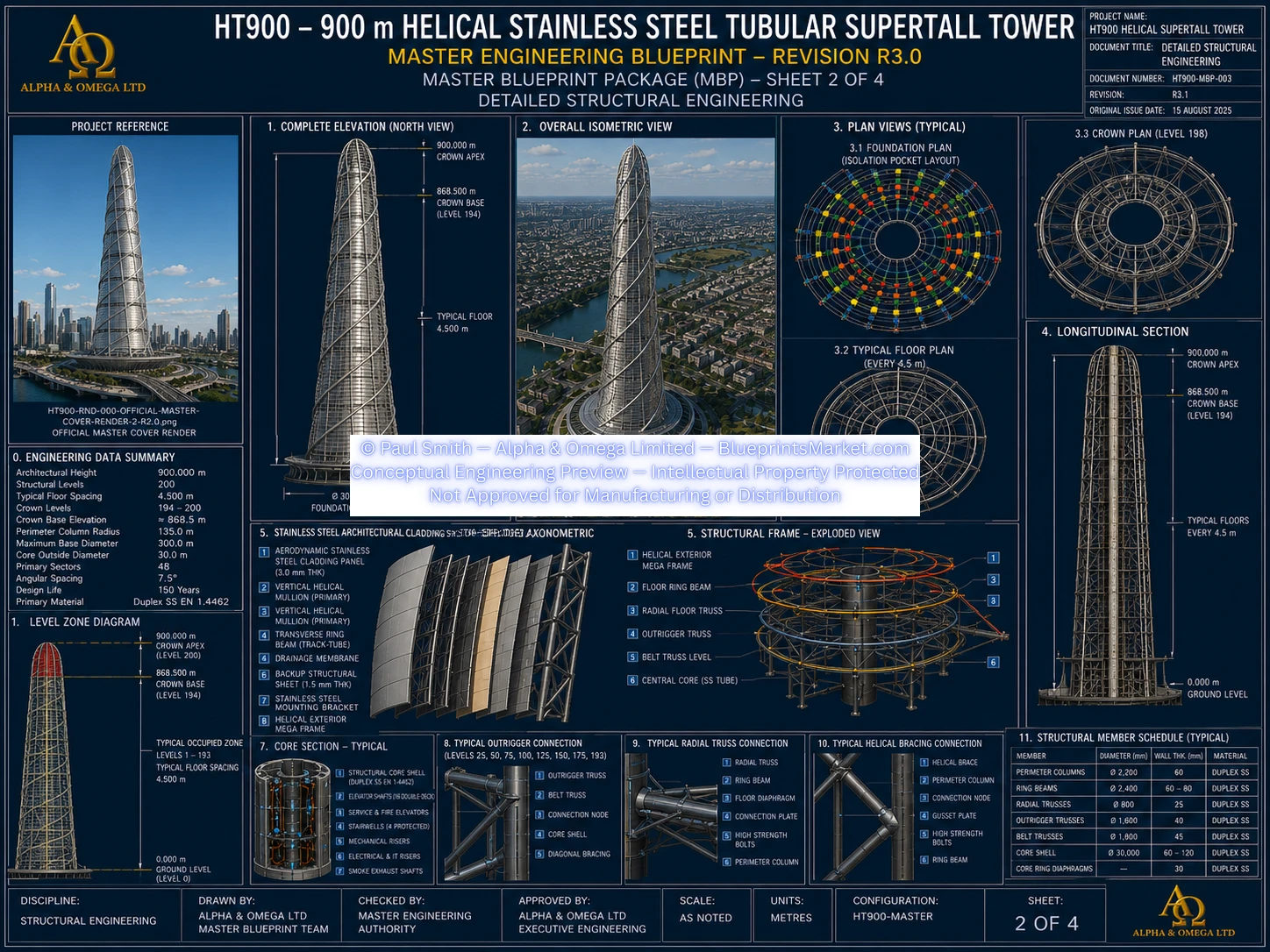
1.0 Structural System Overview
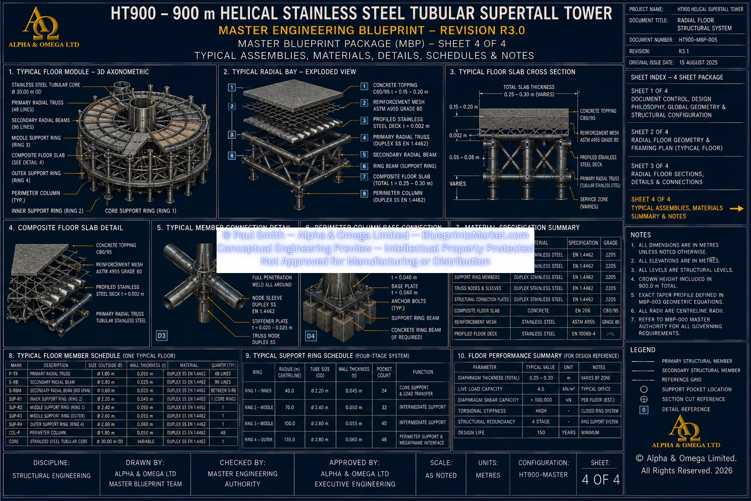
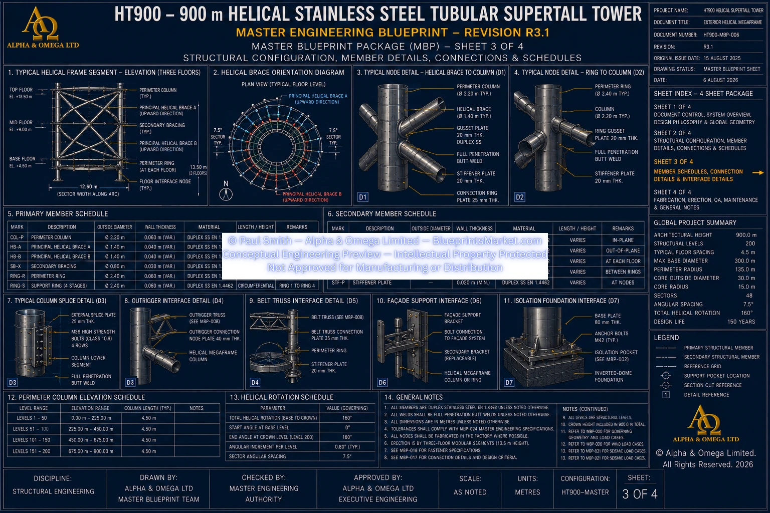
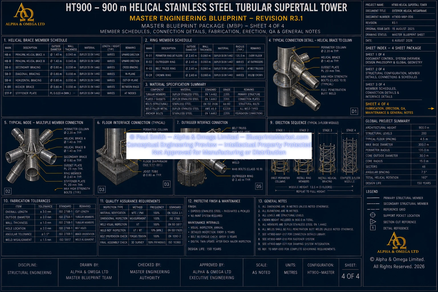
The HT900 is a 900-metre Helical Stainless-Steel Tubular Supertall Tower developed around a unified three-dimensional structural system extending continuously from the deep foundation to the integrated crown.
The tower does not use a reinforced-concrete primary structural core. Its principal above-foundation structure is formed from Duplex Stainless Steel tubular structural systems working together as one coordinated load-resisting framework.
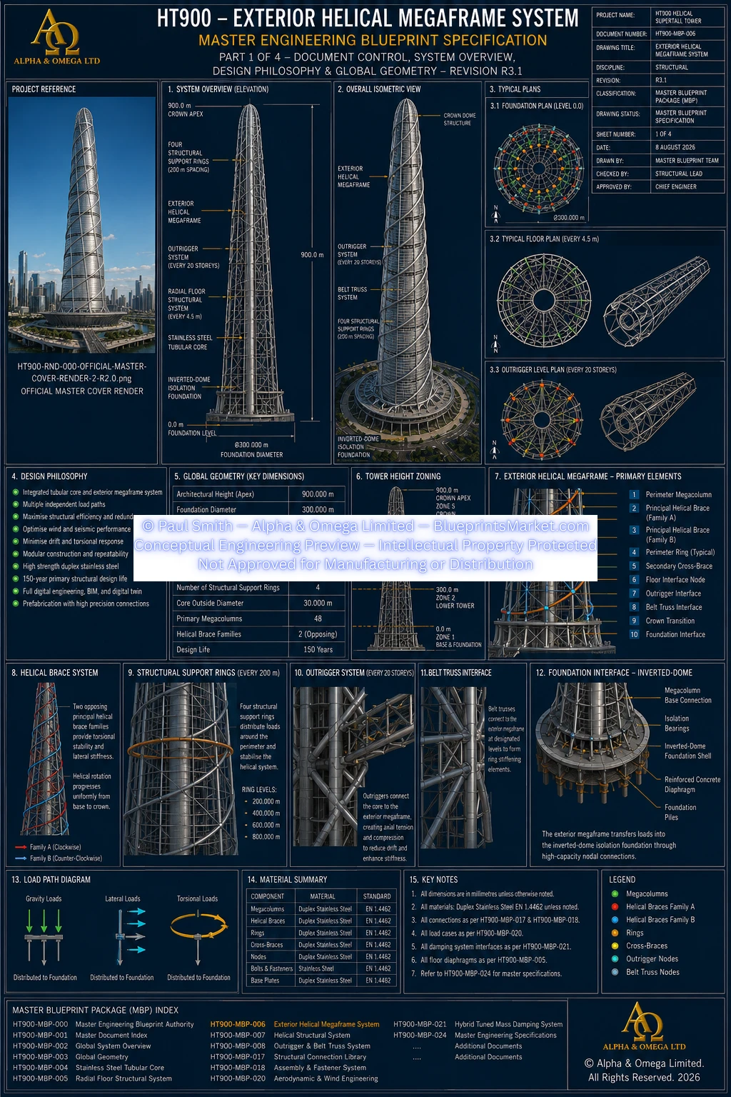
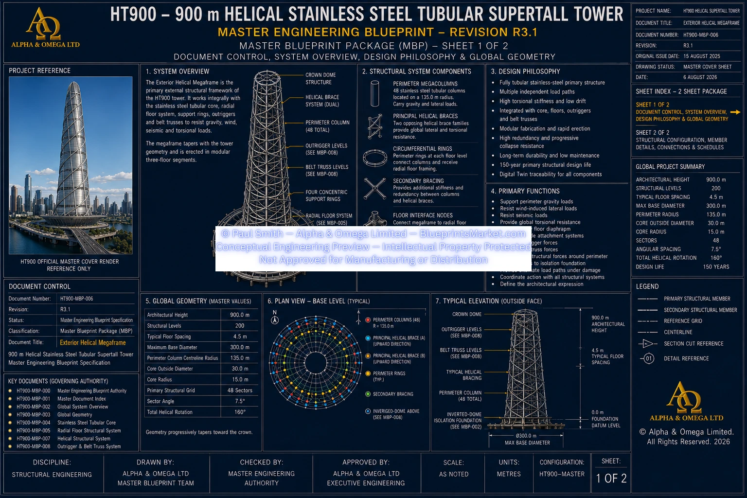
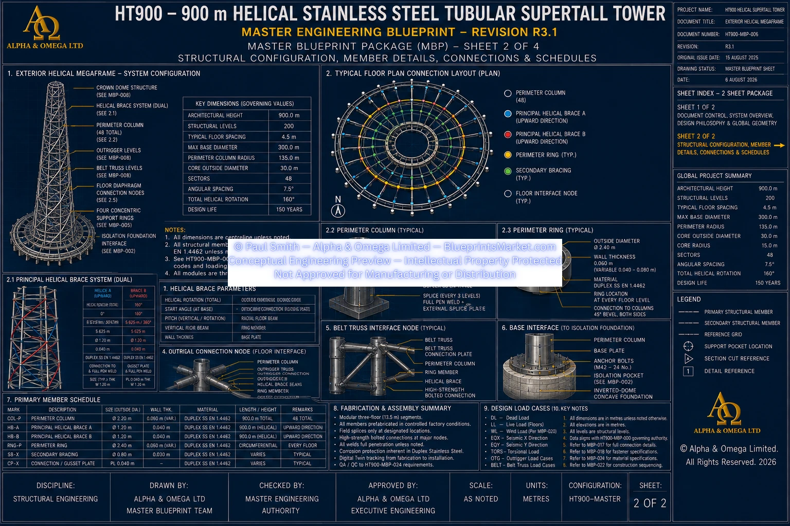
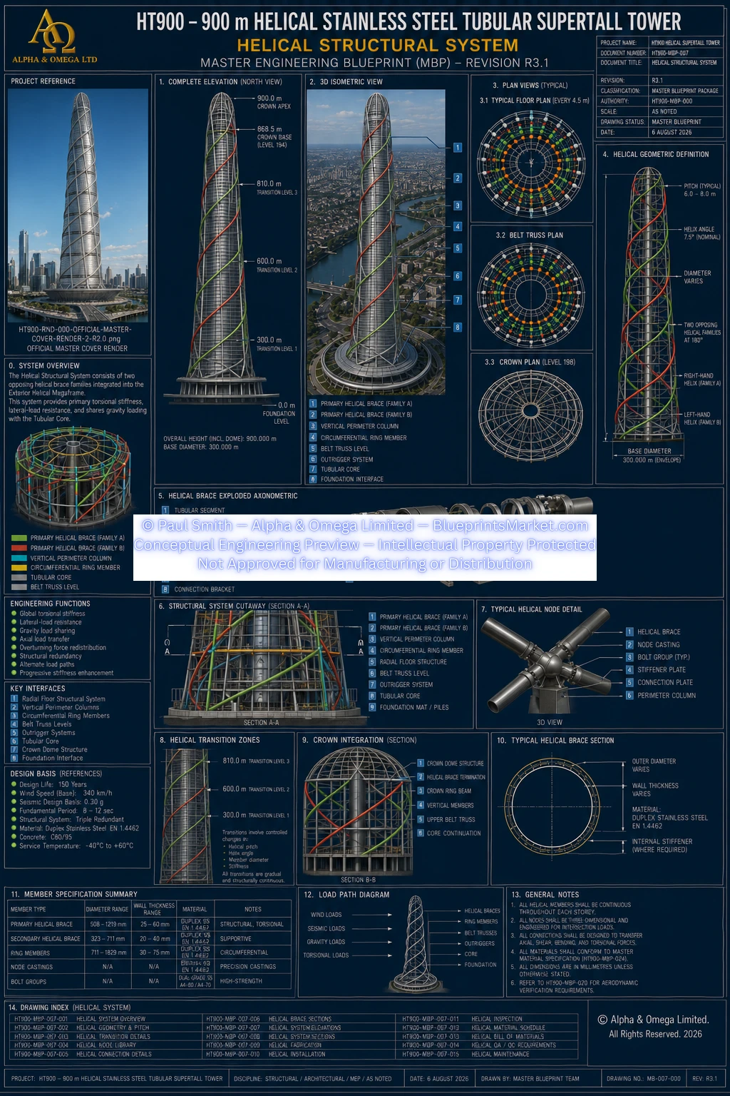
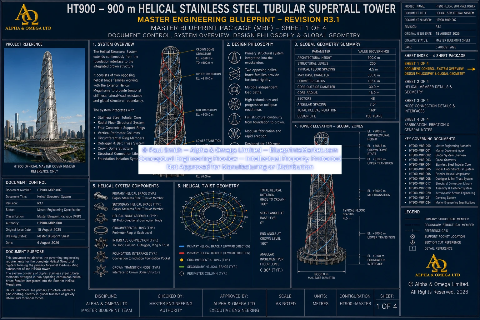
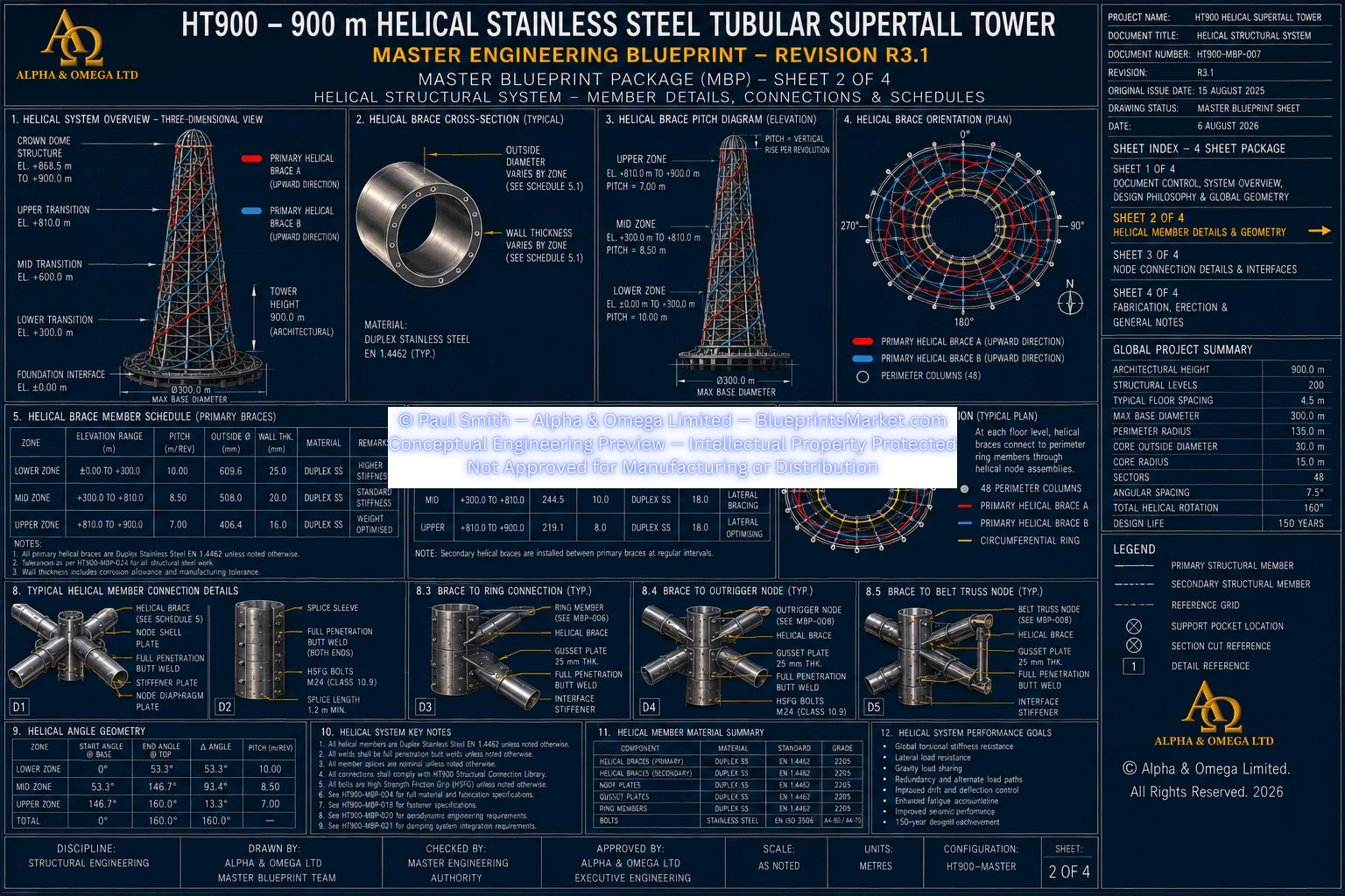
The defining external structural feature is the Helical Structural System, which consists of opposing continuous tubular stainless-steel helical brace families integrated directly into the Exterior Helical Megaframe.
These helical members are primary load-bearing structural elements. They are not decorative façade members and participate directly in the transfer of gravity, wind, seismic and torsional forces.
2.0 Governing Structural Baseline
| Architectural Height | 900 m |
|---|---|
| Structural Levels | 200 |
| Typical Structural Level Spacing | 4.5 m |
| Regular Occupied Levels | Levels 1–193 |
| Integrated Crown Levels | Levels 194–200 |
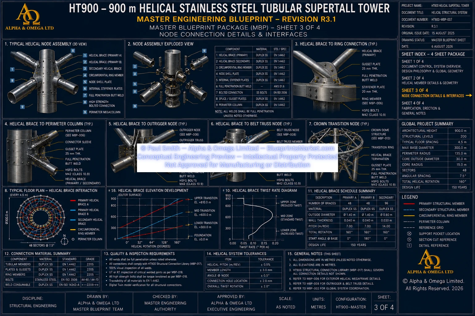
| Crown Base Elevation | Approximately 868.5 m |
| Crown Apex | 900 m |
| Maximum Base Envelope Diameter | 300 m |
| Perimeter Column Centreline Radius | 135 m |
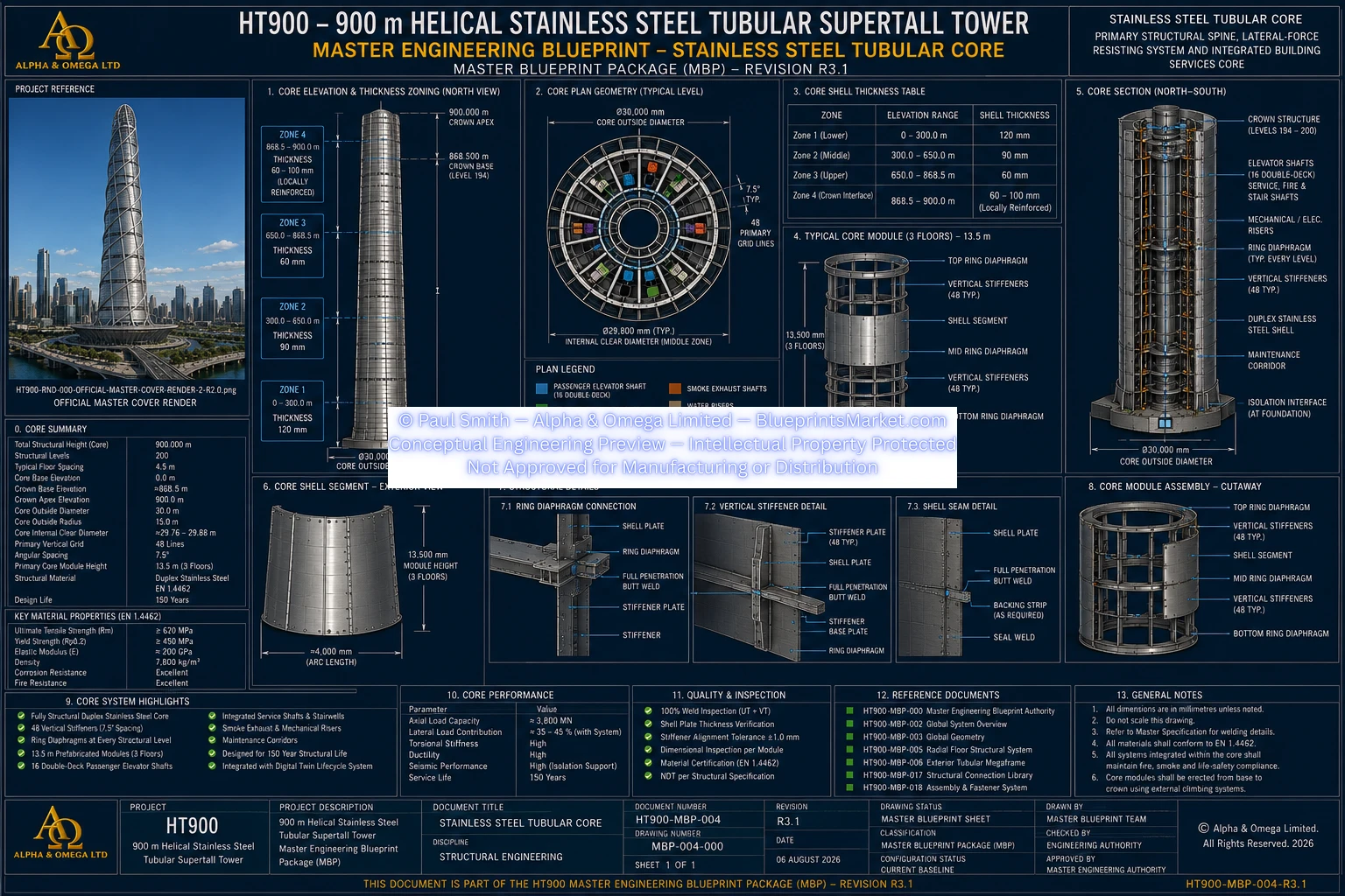
| Tubular Structural Core Diameter | 30 m |
| Primary Structural Grid | 48 sectors |
| Primary Angular Spacing | 7.5° |
| Total Structural Rotation | 160° |
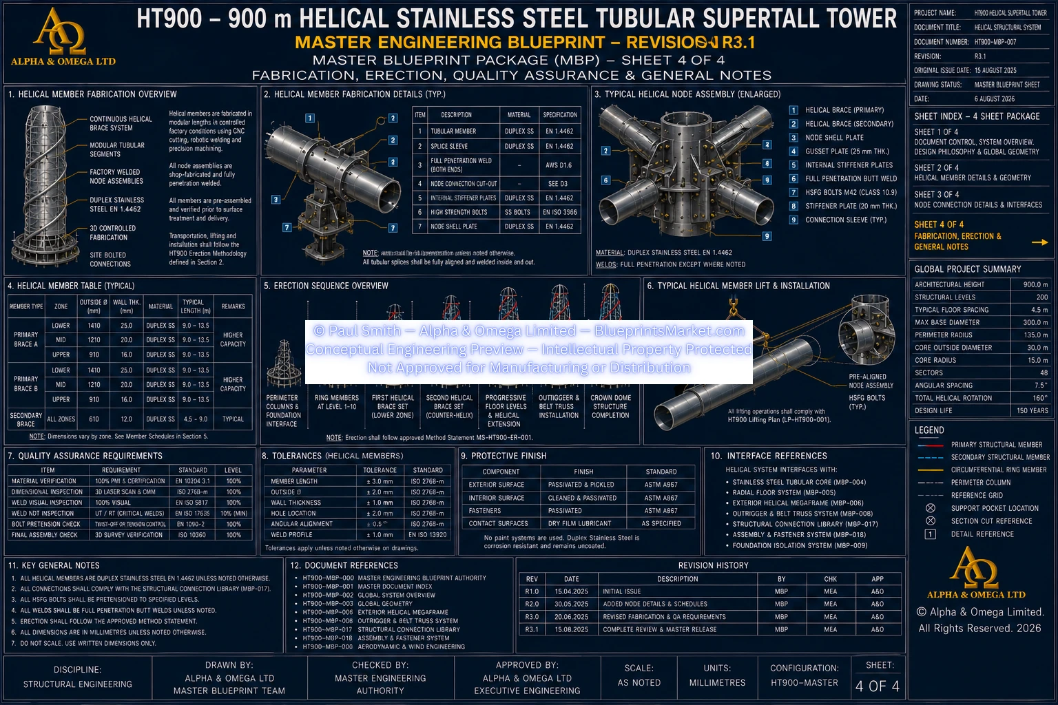
| Average Rotation per Structural Level | Approximately 0.8° |
| Primary Structural Design Life | 150 years |
The tower is continuously tapered and helical rather than a constant-diameter cylindrical structure.
3.0 Global Structural Hierarchy
The complete HT900 structural system is formed from a hierarchy of interconnected systems.
- Integrated Crown Dome Structure
- Helical Structural System
- Exterior Helical Megaframe
- 48 Perimeter Tubular Megacolumns
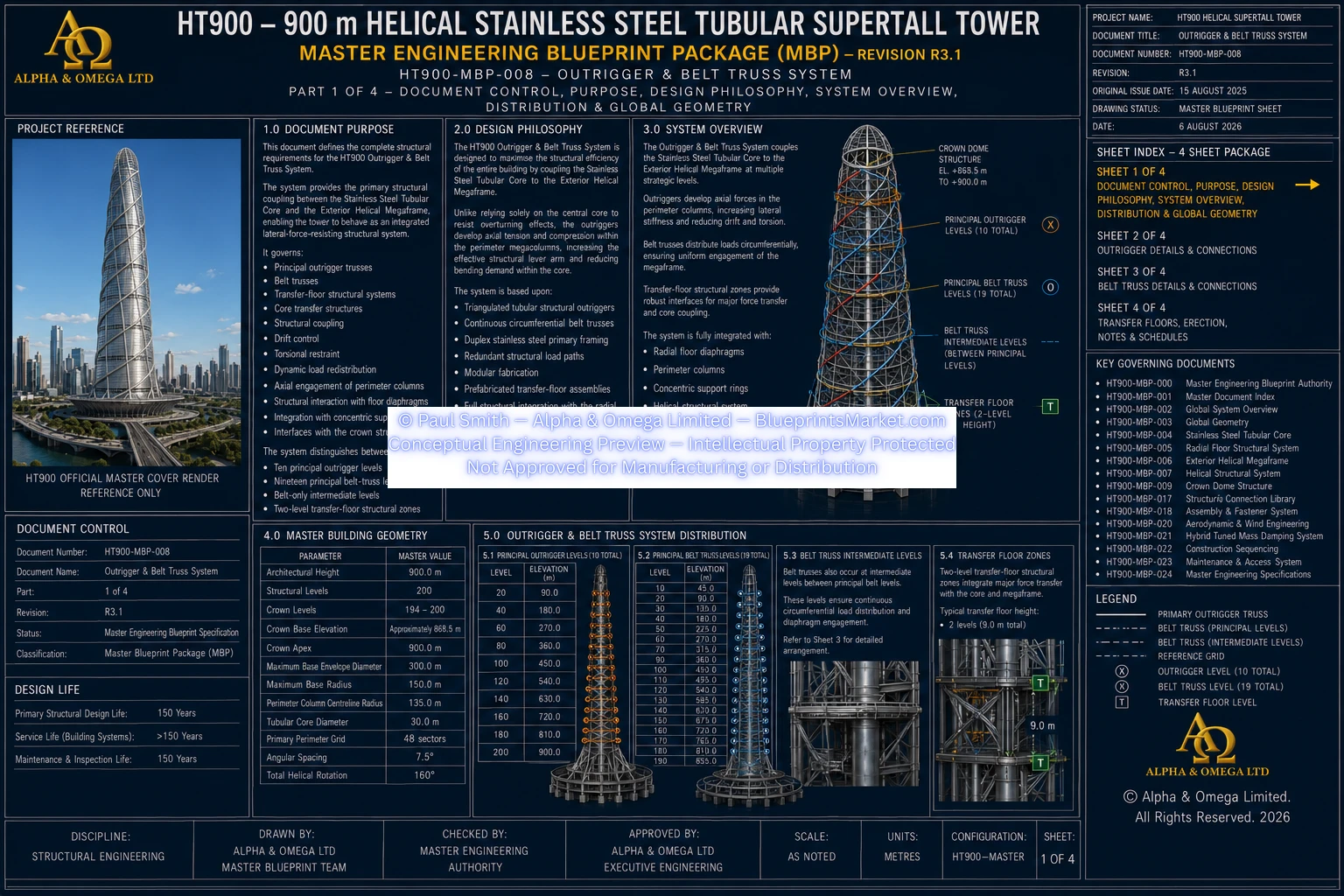
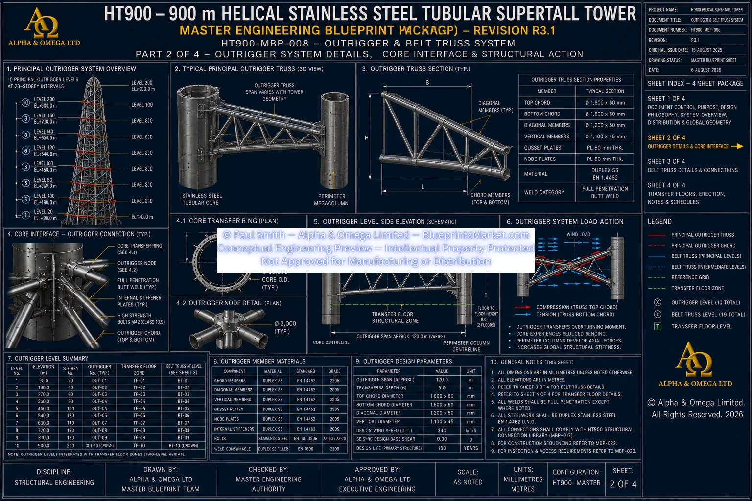
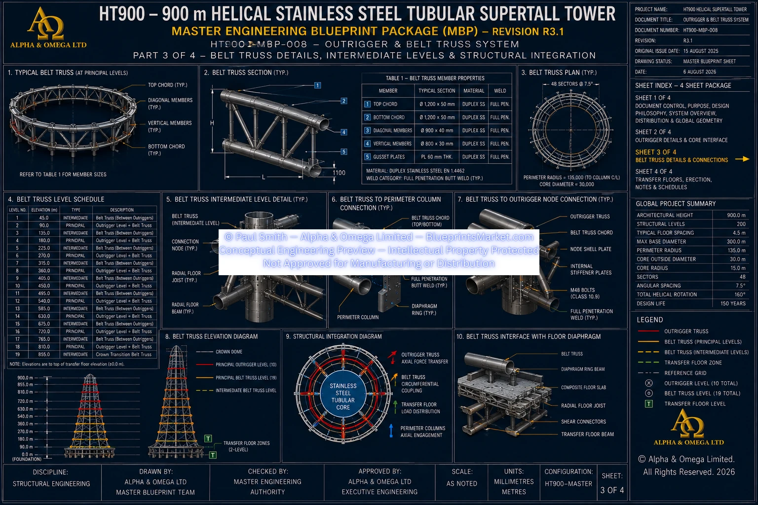
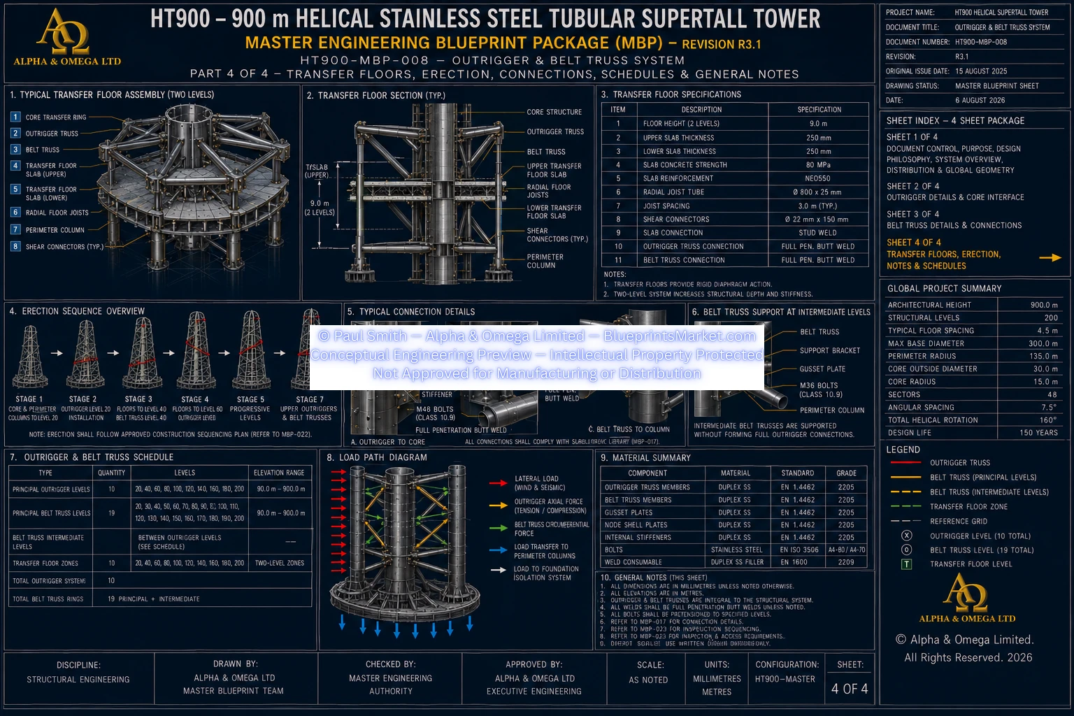
- Outrigger & Belt Truss System
- Radial Floor Structural System
- Four Concentric Structural Support Rings
- 30 m Tubular Stainless-Steel Structural Core
- Foundation-Level Structural Transfer System
- Seismic Isolation System
- 300 m Inverted-Dome Foundation
- Deep Foundation System
These systems are not independent structures. They are designed to act together as one continuous three-dimensional structural network.
4.0 Helical Structural System
The Helical Structural System forms the principal torsional load-resisting subsystem of the HT900 tower.
It extends continuously from the foundation interface through the complete tower height and into the integrated Crown Dome.
The system is formed from modular Duplex Stainless-Steel tubular members connected through engineered three-dimensional structural nodes.
Primary Helical Architecture
- Two opposing continuous helical brace families
- Primary load-bearing helical tubular members
- Secondary helical tubular members
- Circumferential structural ring members
- Vertical perimeter megacolumns
- Three-dimensional structural node assemblies
- Radial floor interfaces
- Outrigger interfaces
- Belt-truss interfaces
- Crown structural transition
5.0 Primary Structural Functions
The helical structural architecture performs multiple structural functions simultaneously.
Global Structural Functions
- Provides global torsional stiffness
- Provides lateral-load resistance
- Shares gravity loading with the tubular core and perimeter megaframe
- Transfers axial forces through continuous helical load paths
- Redistributes overturning forces
- Increases structural redundancy
- Provides alternative structural load paths
- Supports progressive-collapse resistance
- Improves global structural robustness
Aerodynamic Structural Functions
- Works with the tapered tower form
- Disrupts coherent flow patterns
- Reduces synchronised vortex-shedding tendencies
- Reduces across-wind excitation tendencies
- Assists in reducing torsional wind response
Final aerodynamic performance requires project-specific Computational Fluid Dynamics, boundary-layer wind-tunnel testing and aeroelastic verification.
6.0 Structural Exoskeleton
The HT900 exterior structural exoskeleton is formed by more than the visible helical members alone.
It includes:
- 48 vertical perimeter megacolumns
- Primary helical braces
- Secondary helical braces
- Circumferential ring members
- Structural node assemblies
- Radial floor interfaces
- Belt trusses
- Outrigger systems
Together these components create a continuous tubular stainless-steel perimeter framework that participates in gravity, lateral and torsional load resistance.
7.0 Tapered Helical Geometry
The structural envelope progressively reduces in diameter toward the crown while maintaining continuous helical structural alignment.
| Base Envelope | Approximately 300 m diameter |
|---|---|
| Mid-Height Envelope | Approximately 220 m diameter |
| Crown Base Envelope | Approximately 60 m diameter |
Principal geometric transitions occur at approximately 300 m, 600 m and 810 m elevation before the tower enters the integrated Crown Dome zone beginning at approximately 868.5 m.
8.0 Primary Helical Members
Primary helical members are load-bearing Duplex Stainless-Steel Circular Hollow Sections integrated directly into the exterior structural megaframe.
They are designed to participate in:
- Axial compression
- Axial tension
- Wind-induced structural loading
- Seismic loading
- Torsional loading
- Dynamic structural response
- Progressive load redistribution
Member sizes vary through the tower height according to elevation, gravity loading, wind loading, torsional demand, fatigue requirements, dynamic response and crown geometry.
No single helical-member size applies throughout the complete tower.
9.0 Secondary Helical Structural Members
Secondary helical members reinforce the primary helical structural network and provide additional continuity and redundancy.
Primary Functions
- Increase local stiffness
- Provide additional structural redundancy
- Redistribute local forces
- Stabilise structural nodes
- Increase torsional resistance
- Improve fatigue behaviour
Secondary helices connect with the primary helices, circumferential rings, vertical perimeter columns and radial floor framing.
10.0 Circumferential Structural Ring Members
Continuous circumferential ring members occur at the structural floor levels and connect the vertical, radial and helical structural systems.
Their functions include:
- Maintaining circular structural geometry
- Tying helical members together
- Connecting radial floor trusses
- Providing diaphragm restraint
- Resisting circumferential deformation
- Increasing torsional rigidity
- Redistributing local structural loading
- Integrating with the concentric floor support-ring system
11.0 Stainless-Steel Tubular Core Integration
The central structural core is a continuous 30-metre-diameter circular Duplex Stainless-Steel tubular structural shell.
No reinforced-concrete structural core is incorporated anywhere within the HT900 tower.
The core works together with:
- Radial floor trusses
- Four concentric support rings
- Exterior Helical Megaframe
- Helical bracing
- Belt trusses
- Outriggers
- Integrated crown structure
- Foundation and seismic-isolation system
This creates shared structural load paths rather than forcing the central core to resist all tower loads independently.
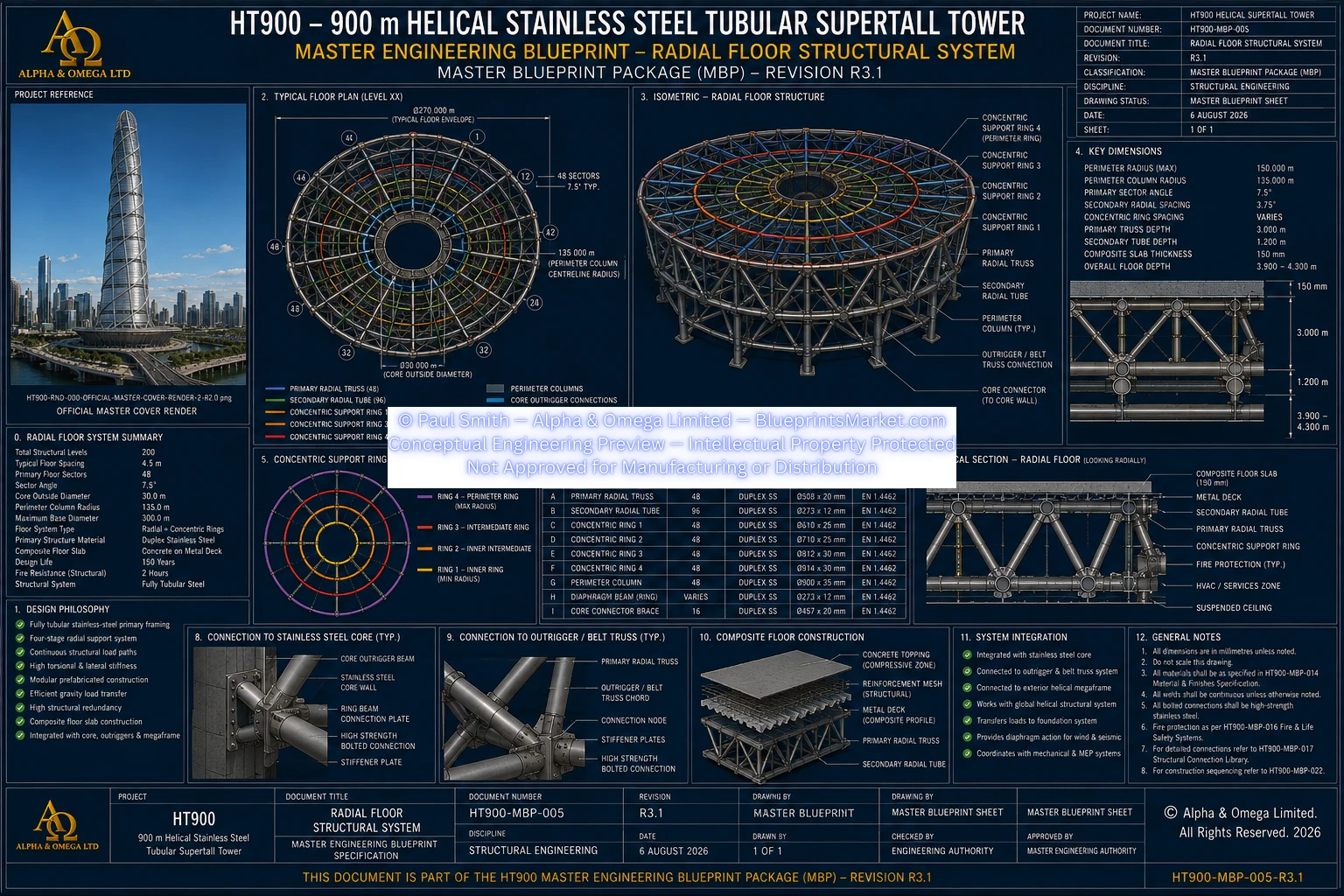
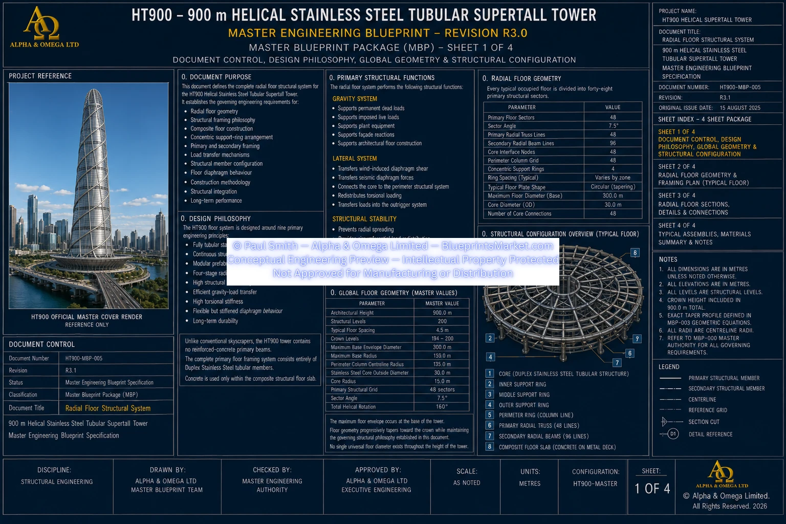
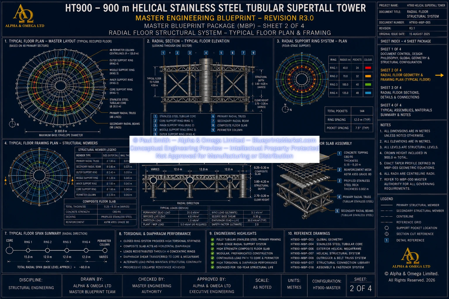
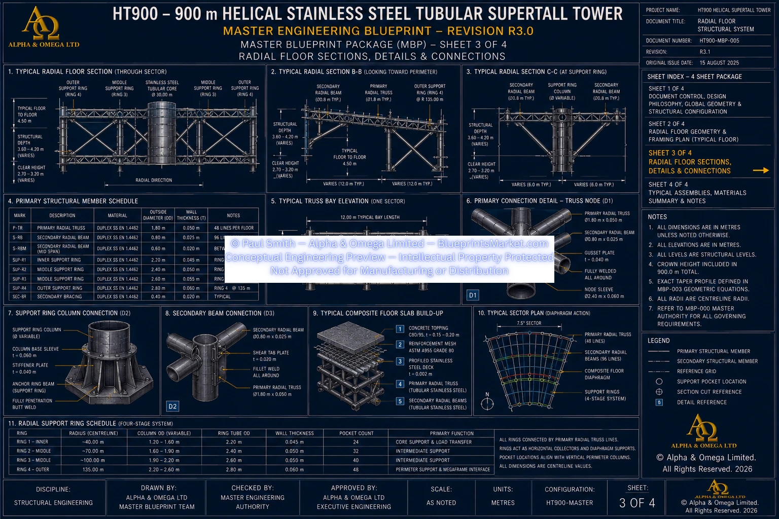
12.0 Radial Floor Structural Integration
Each typical floor uses a 48-sector radial structural grid extending between the central tubular core and exterior structural megaframe.
The radial floor structure is supported through four principal concentric structural rings beyond the core interface.
| Core Interface | 15 m radius |
|---|---|
| Ring R1 | 45 m radius |
| Ring R2 | 75 m radius |
| Ring R3 | 105 m radius |
| Perimeter Ring R4 | 135 m radius |
This creates typical radial structural bays of approximately 30 metres and avoids reliance upon unrealistic unsupported core-to-perimeter spans.
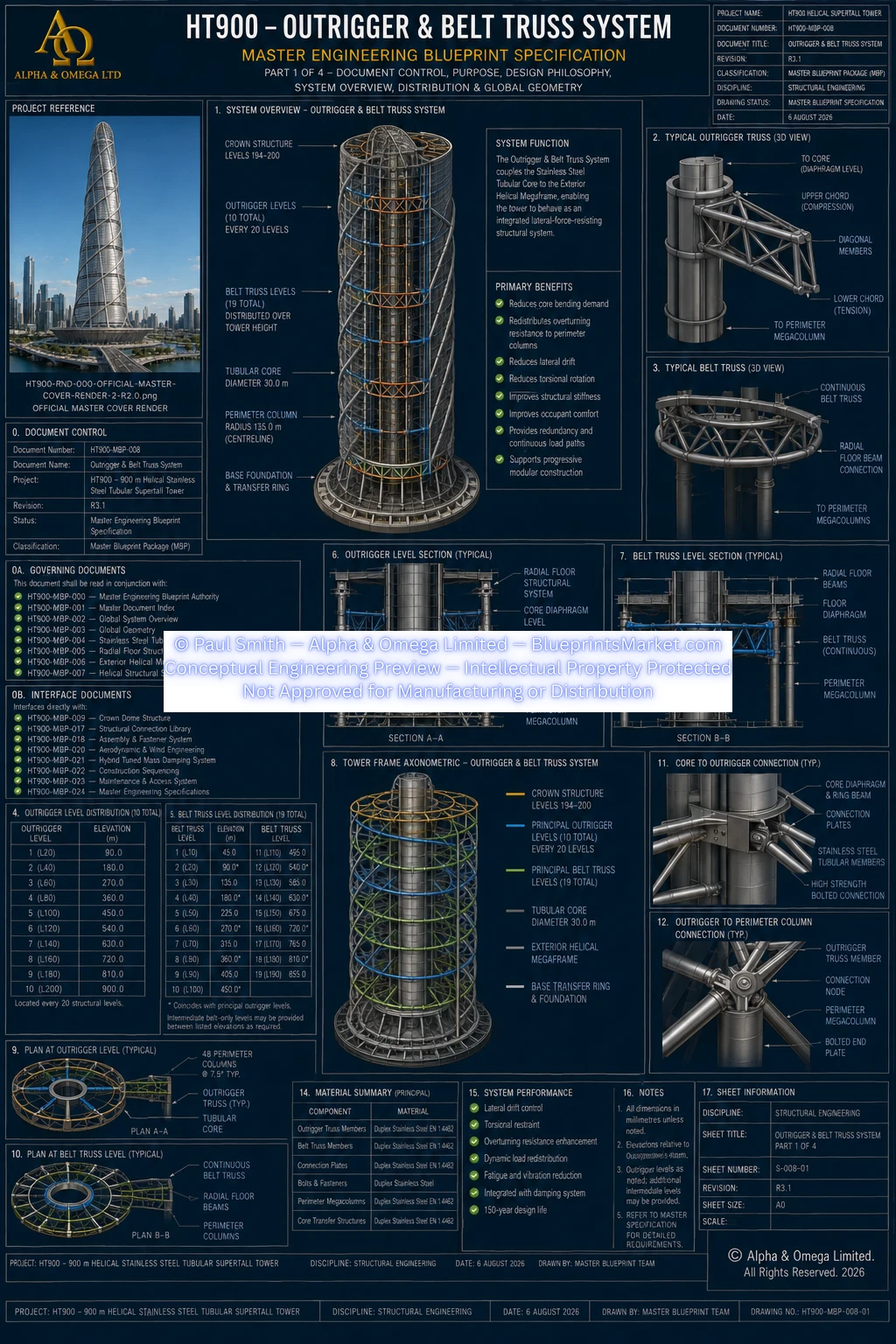
13.0 Outrigger & Belt Truss Integration
The helical structure is directly connected to the Outrigger & Belt Truss System.
The current baseline incorporates:
- 10 principal outrigger levels
- Principal outrigger levels at approximately 20-floor intervals
- 19 principal belt-truss levels
- Belt-truss levels at approximately 10-floor intervals
- Integrated crown transfer structure
These systems connect the central tubular core to the exterior megaframe and engage the perimeter megacolumns in resisting overturning and lateral forces.
14.0 Three-Dimensional Structural Nodes
Structural intersections throughout the helical system use engineered Duplex Stainless-Steel node assemblies.
Typical node relationships may connect:
- Primary helix to primary helix
- Primary helix to secondary helix
- Helix to vertical perimeter column
- Helix to circumferential ring member
- Helix to radial floor framing
- Helix to belt truss
- Helix to outrigger
- Helix to crown structure
The node system supports three-dimensional force transfer, structural continuity, fatigue resistance, modular assembly, inspection access and Structural Health Monitoring interfaces.
15.0 Gravity Load Path
Gravity forces are distributed through multiple coordinated structural systems rather than one isolated vertical frame.
The conceptual gravity-load path is:
Occupancy & Equipment → Composite Floor → Stainless-Steel Floor Framing → Primary Radial Trusses → Concentric Support Rings → Tubular Core & Exterior Megaframe → Helical Structural Members → Foundation Support System → Deep Foundation
16.0 Wind Load Path
Wind forces enter the structure through the exterior envelope and are distributed throughout the complete three-dimensional structural network.
The conceptual wind-load path is:
Wind → Exterior Façade → Façade Support System → Exterior Helical Megaframe → Primary Helical Members → Circumferential Rings → Floor Diaphragms → Belt Trusses → Outriggers → Tubular Core → Isolation Foundation → Deep Foundation
17.0 Torsional Load Path
Torsional resistance is one of the defining functions of the Helical Structural System.
Wind eccentricity and other torsional actions are distributed through the opposing helical brace families, circumferential rings, radial floor structure, exterior megaframe and central tubular core.
This continuous helical geometry allows torsional forces to be redistributed through the complete building perimeter rather than concentrated at isolated braces or structural levels.
18.0 Seismic Structural Integration
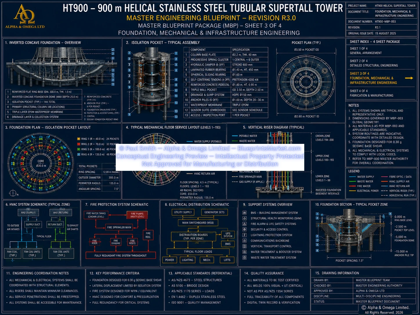
Seismic forces enter the structure through the deep foundation and the 300-metre inverted-dome seismic-isolation system.
The current foundation baseline incorporates:
- 144 seismic-isolation pocket assemblies
- 144 foundation support groups
- 144 pile caps
- 8 deep piles per support group
- 1,152 deep piles in total
Above the isolation system, structural response is distributed into the tubular core, radial floor diaphragms, exterior megaframe and helical structural system.
19.0 Structural Redundancy
High structural redundancy is a central principle of the HT900 structural architecture.
Redundant load paths are provided through:
- 30 m Tubular Stainless-Steel Core
- 48 perimeter megacolumns
- 48 radial floor sectors
- Four concentric structural support rings
- Two opposing helical brace families
- Secondary helical bracing
- Circumferential structural rings
- Outrigger structures
- Belt-truss structures
- Three-dimensional structural nodes
- Integrated crown structure
- Distributed foundation support system
No single principal structural member is intended to operate as the sole load path for the complete tower.
20.0 Structural Material Philosophy
| Primary Helical Members | Duplex Stainless Steel EN 1.4462 |
|---|---|
| Secondary Helical Members | Duplex Stainless Steel EN 1.4462 |
| Circumferential Ring Members | Duplex Stainless Steel EN 1.4462 |
| Structural Nodes | Duplex Stainless Steel EN 1.4462 |
| Primary Floor Framing | Tubular Duplex Stainless Steel |
| Tubular Structural Core | Duplex Stainless Steel EN 1.4462 |
| Exterior Megaframe | Duplex Stainless Steel EN 1.4462 |
Carbon steel is not used as the primary structural material of the Helical Structural System.
Reinforced concrete is limited to approved secondary and substructure applications including foundations, piles, pile caps, pedestals, composite floor toppings and non-core fire partitions.
21.0 Global Structural Performance Objectives
The Helical Structural System contributes to the global performance of the complete tower but is not independently responsible for achieving tower-wide structural targets.
| Primary Structural Design Life | 150 years |
|---|---|
| Serviceability Drift Target | ≤ H/1000 |
| Ultimate Drift Target | ≤ H/500 |
| Peak Occupied-Floor Acceleration Target | ≤ 15 milli-g |
These remain conceptual project targets and require verification through nonlinear global analysis, seismic analysis, dynamic modelling, CFD and wind-tunnel testing.
22.0 Modular Structural Construction
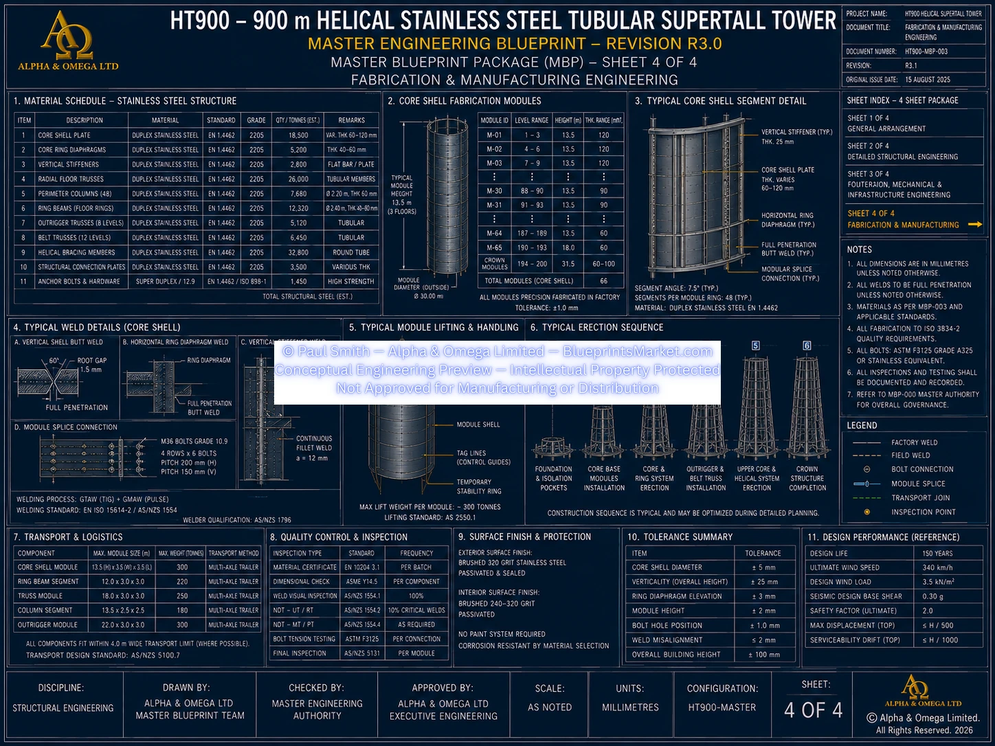
The Helical Structural System is designed for factory-prefabricated modular construction rather than unrestricted field fabrication.
Typical modular assemblies may include:
- Primary helical tubular segments
- Secondary helical assemblies
- Structural node assemblies
- Circumferential ring interfaces
- Survey-control interfaces
- Temporary erection interfaces
- Lifting interfaces
The governing erection philosophy coordinates helical structural modules with the tubular core, radial floors, perimeter megacolumns, ring members, outriggers and belt trusses.
Complete floors are not transported or lifted as single assemblies.
23.0 Structural Connection Philosophy
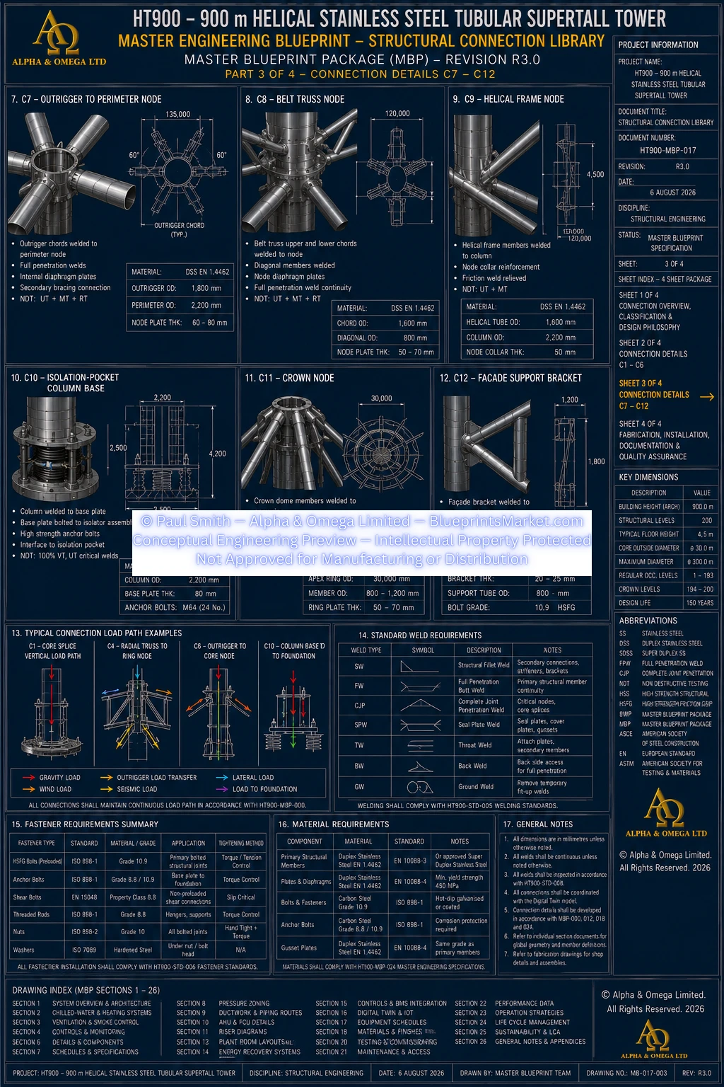
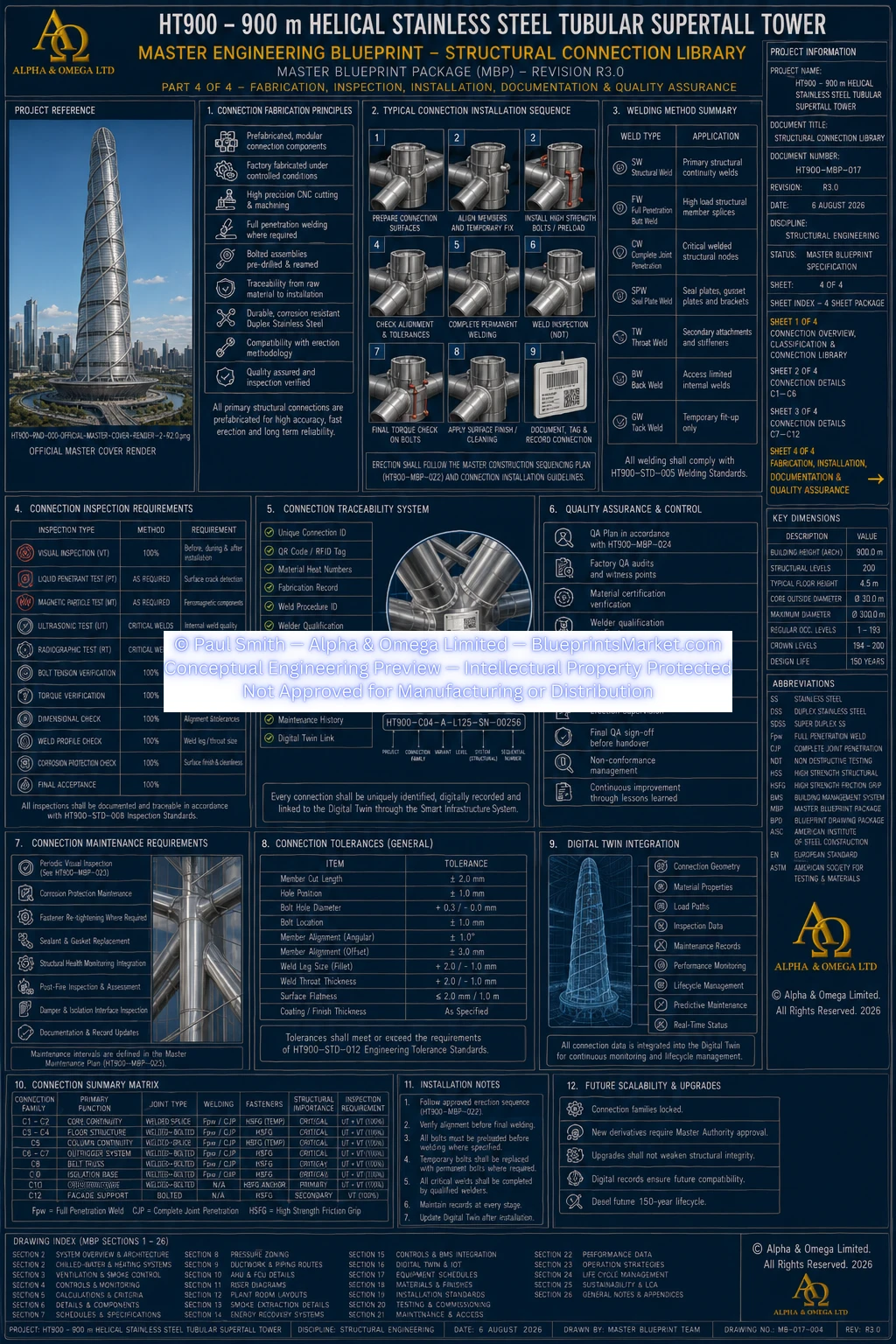
All principal helical structural connections are coordinated through the HT900 Structural Connection Library and Assembly & Fastener System.
Structural connections are required to provide:
- Continuous axial-force transfer
- Shear transfer
- Bending resistance
- Torsional transfer
- Dynamic-load transfer
- Redundant force paths
- Inspection access
- Lifecycle traceability
Detailed weld procedures, bolt schedules, node geometry, plate sizes and fabrication information remain within the licensed Master Blueprint Package.
24.0 Structural Health Monitoring
The Helical Structural System forms part of the tower-wide Structural Health Monitoring and Digital Twin architecture.
Monitoring may include:
- Structural strain
- Member deformation
- Structural movement
- Vibration
- Dynamic response
- Fatigue behaviour
- Connection performance
- Temperature effects
- Long-term structural condition
Manufacturing, installation, inspection and maintenance records can remain linked to individual structural assets through the Digital Twin system.
25.0 Inspection & Lifecycle Access
The permanent helical structural system is intended to remain inspectable throughout the 150-year primary structural design life.
Inspection provisions may include:
- Structural inspection galleries
- Internal maintenance walkways
- External maintenance platforms
- Structural-node inspection access
- Inspection hatches
- Structural monitoring interfaces
- Remote inspection systems
- Non-destructive examination
- Crown maintenance interfaces
26.0 Exterior Façade Relationship
The exterior cladding and curtain-wall system is a secondary environmental envelope mounted outside the primary tubular stainless-steel megaframe.
The façade does not replace, interrupt or redefine the primary structural load path.
The tubular core, radial floor structure, perimeter megacolumns, helical structural members, ring structures, outriggers, belt trusses and crown remain the primary load-bearing structural systems.
27.0 Master Structural Logic
The defining structural principle of the HT900 is that the tower does not rely upon one central spine or one exterior bracing system acting independently.
Instead, the two opposing helical brace families are integrated with 48 perimeter megacolumns, 48 radial floor sectors, four concentric structural support rings, the tubular stainless-steel core, outriggers, belt trusses and the Crown Dome.
These systems establish continuous three-dimensional load paths that distribute gravity, wind, seismic and torsional forces through multiple interconnected structural routes.
The result is a unified tubular stainless-steel megastructure extending continuously from the seismic-isolation foundation to the 900-metre architectural apex.
28.0 Engineering Summary
The HT900 Structural System is a fully integrated tubular stainless-steel structural architecture developed around a continuous 30-metre Duplex Stainless-Steel Tubular Core, 48 perimeter megacolumns, 48 radial floor sectors, four concentric support rings, opposing helical brace families, circumferential structural rings, outriggers, belt trusses and an integrated Crown Dome.
The Helical Structural System forms the primary torsional load-resisting exoskeleton and participates directly in gravity, lateral, seismic and dynamic load transfer.
The structural architecture continues through the 144-unit seismic-isolation system, 300-metre inverted-dome foundation and 1,152-pile deep-foundation network, providing a complete conceptual load path from the architectural apex to competent founding strata.
29.0 Conceptual Engineering Notice
This public page presents the high-level structural architecture and engineering philosophy of the HT900 Structural System.
Detailed member dimensions, wall-thickness schedules, structural-node geometry, connection plates, weld procedures, fastener schedules, fabrication tolerances, erection tolerances, structural calculations, connection forces, finite-element results, detailed assembly procedures and other implementation-level engineering information are contained within the licensed HT900 Master Blueprint Package and are intentionally not reproduced on this public overview page.
Any real-world implementation would require complete project-specific nonlinear structural analysis, wind-tunnel testing, Computational Fluid Dynamics, seismic analysis, soil-structure interaction modelling, connection engineering, fabrication engineering, construction-stage analysis, regulatory approval and certification by appropriately qualified and licensed engineering professionals.
HT900-MBP-004 — STAINLESS STEEL TUBULAR CORE
HT900-MBP-005 — RADIAL FLOOR STRUCTURAL SYSTEM
HT900-MBP-006 — EXTERIOR HELICAL MEGA FRAME
HT900-MBP-007 — HELICAL STRUCTURAL SYSTEM
HT900-MBP-008 — OUTRIGGER & BELT TRUSS SYSTEM
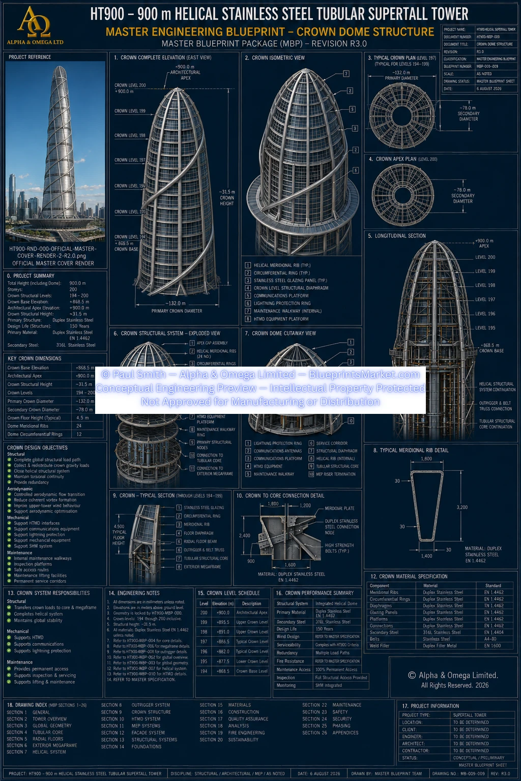
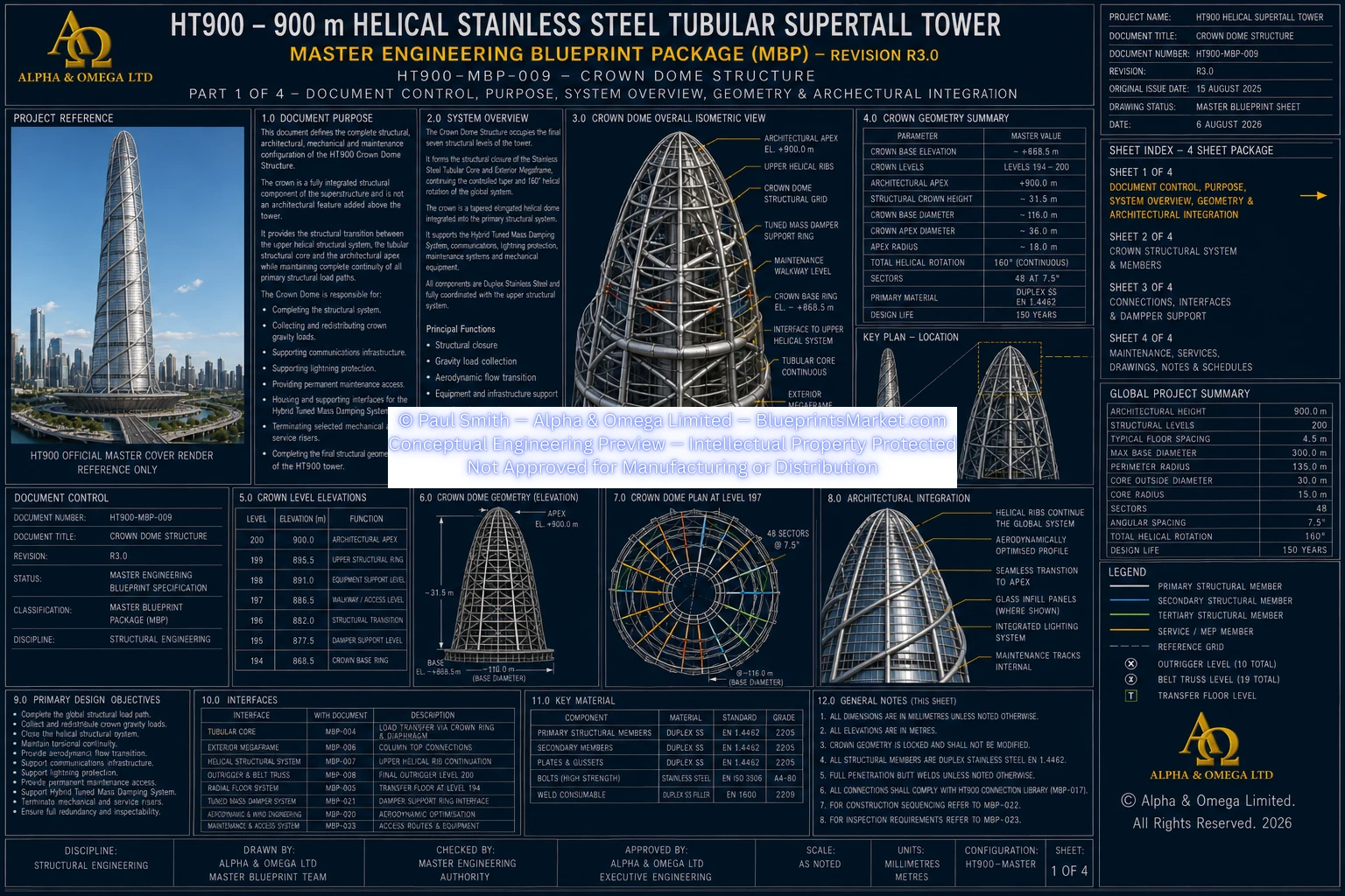
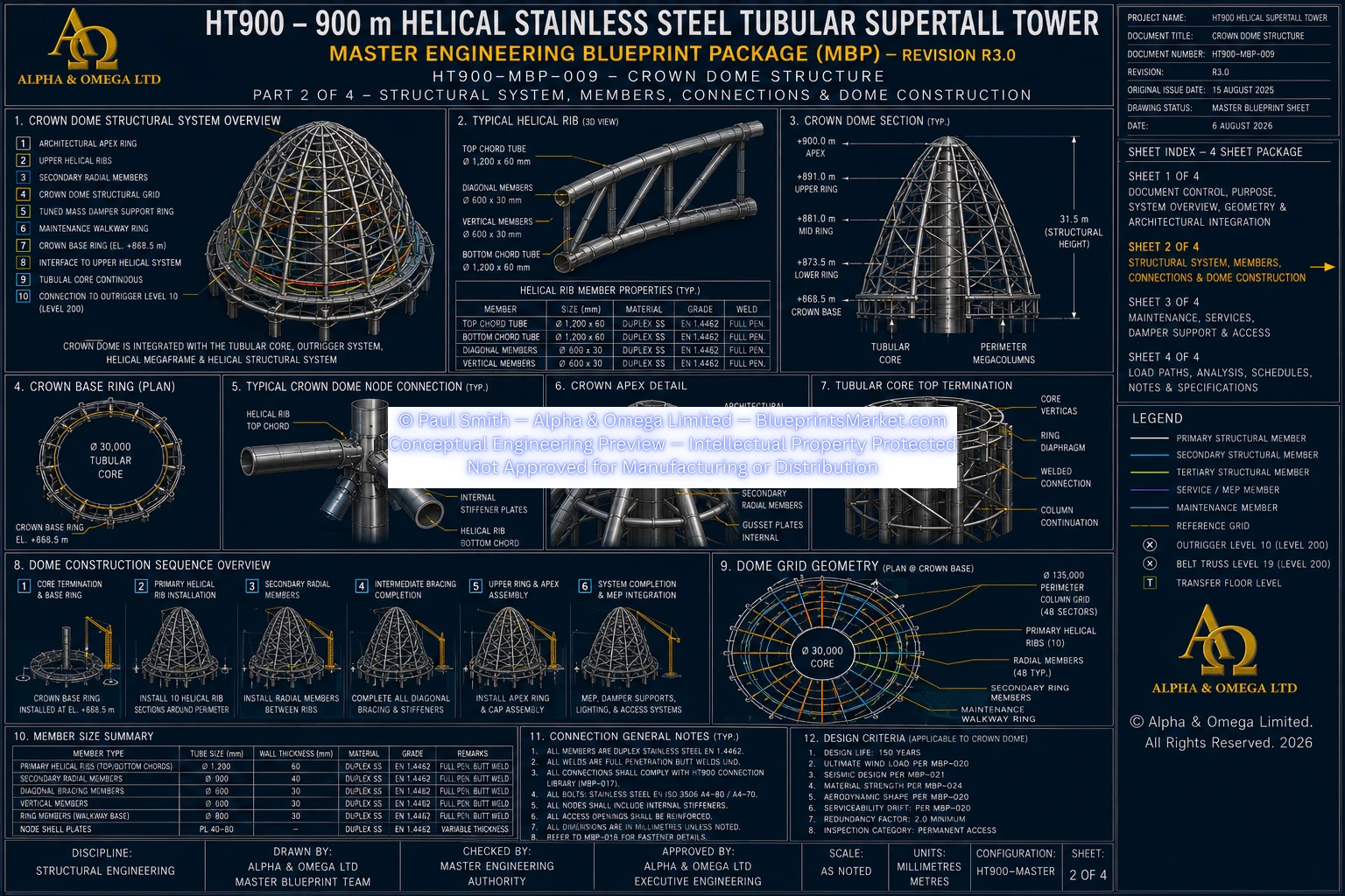
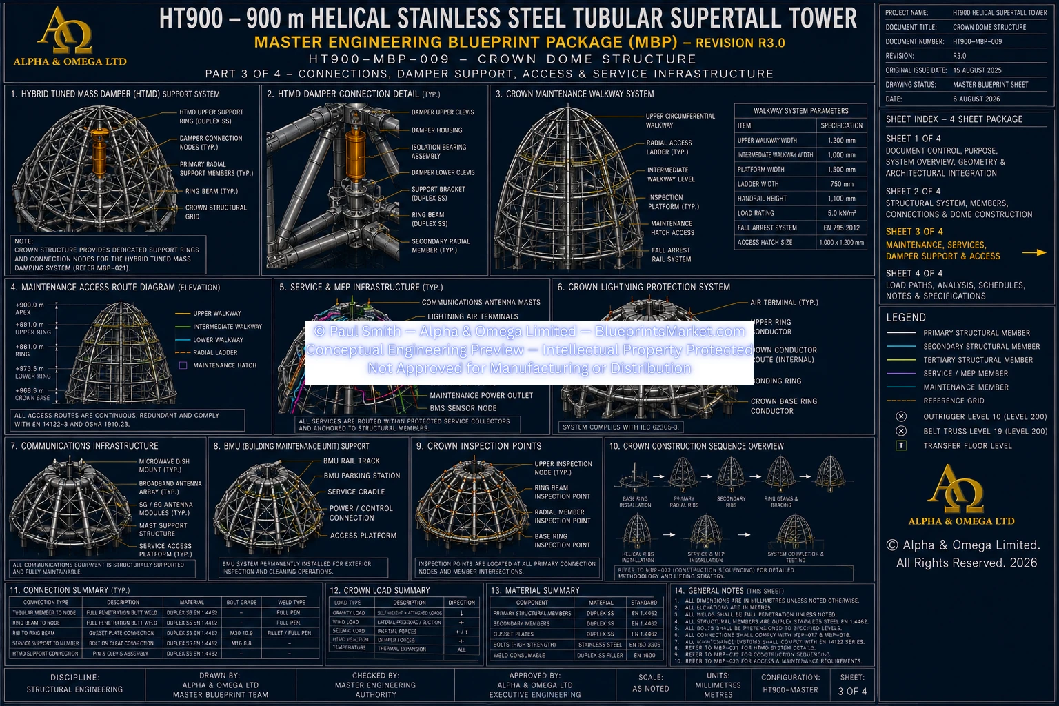
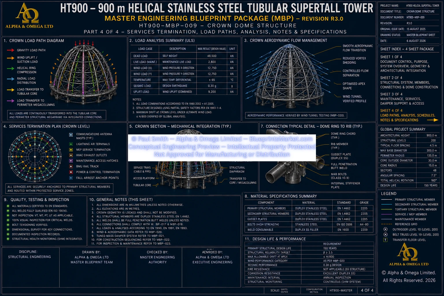
HT900-MBP-009 — CROWN DOME STRUCTURE
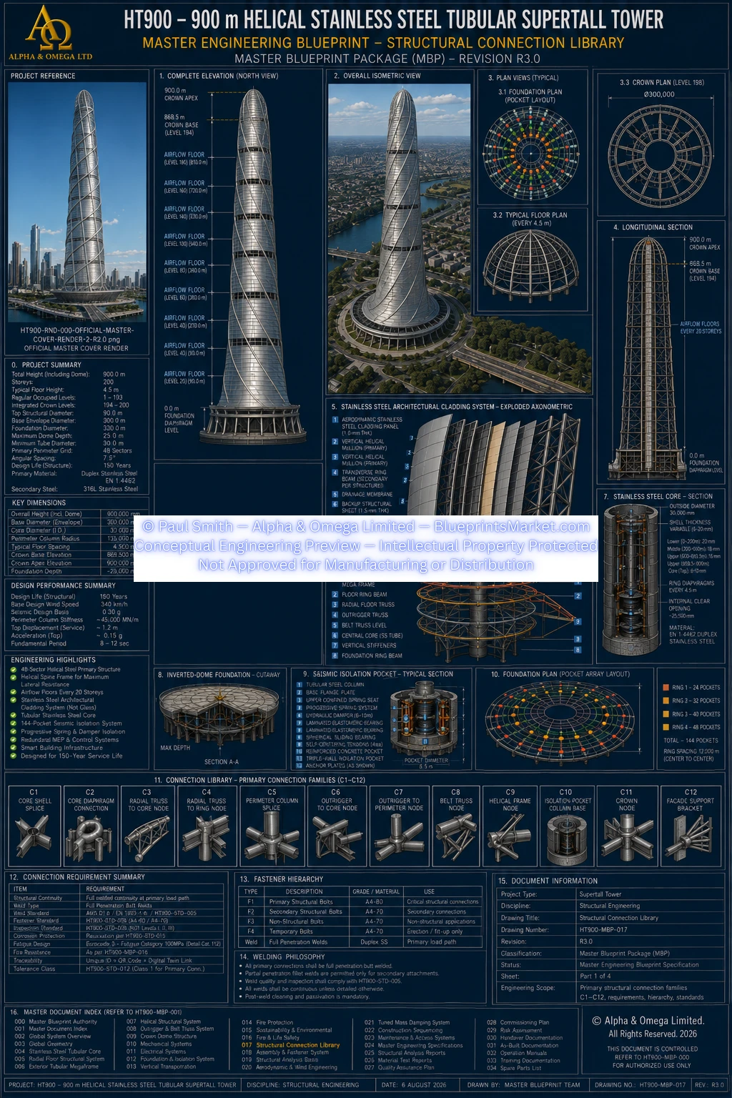
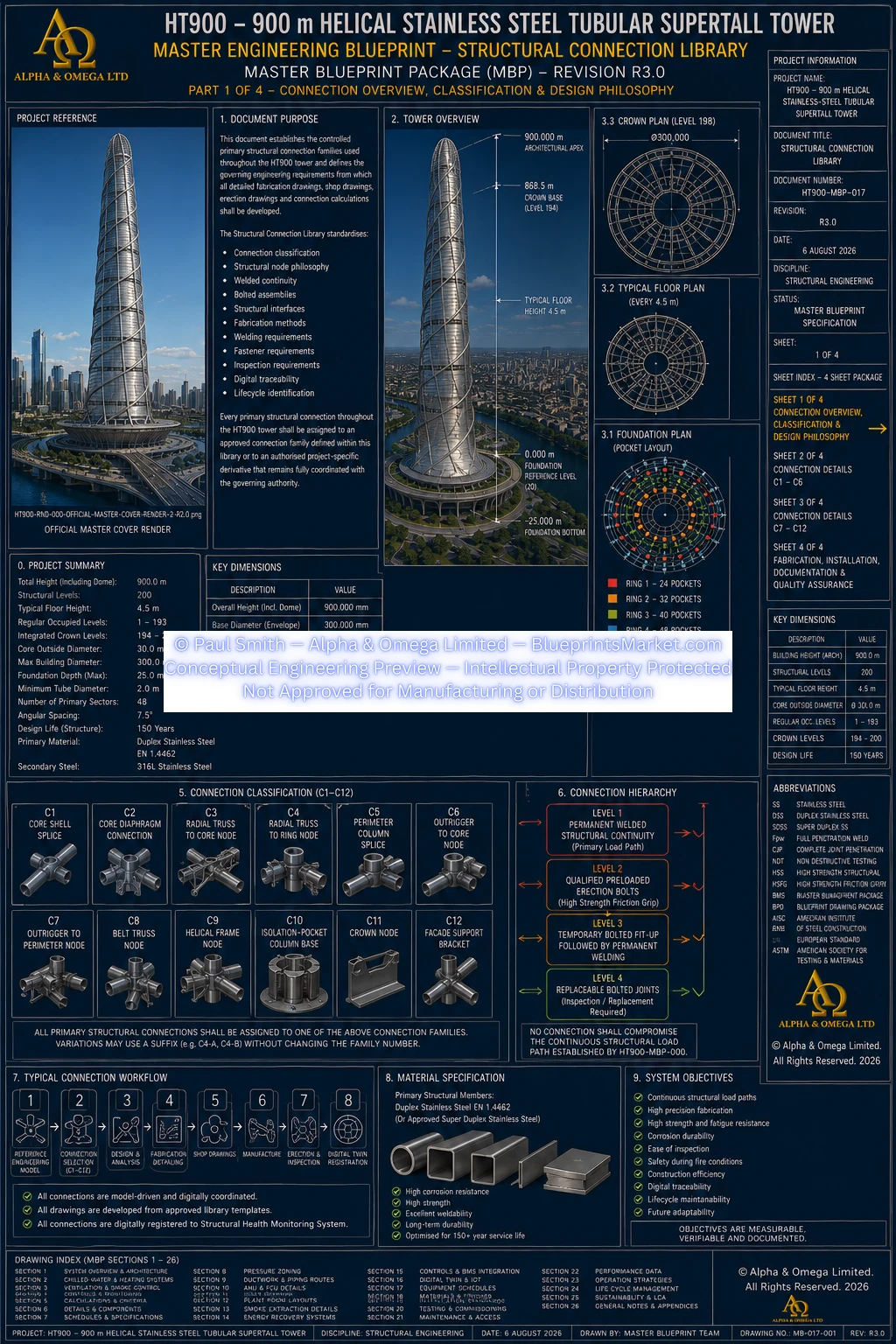
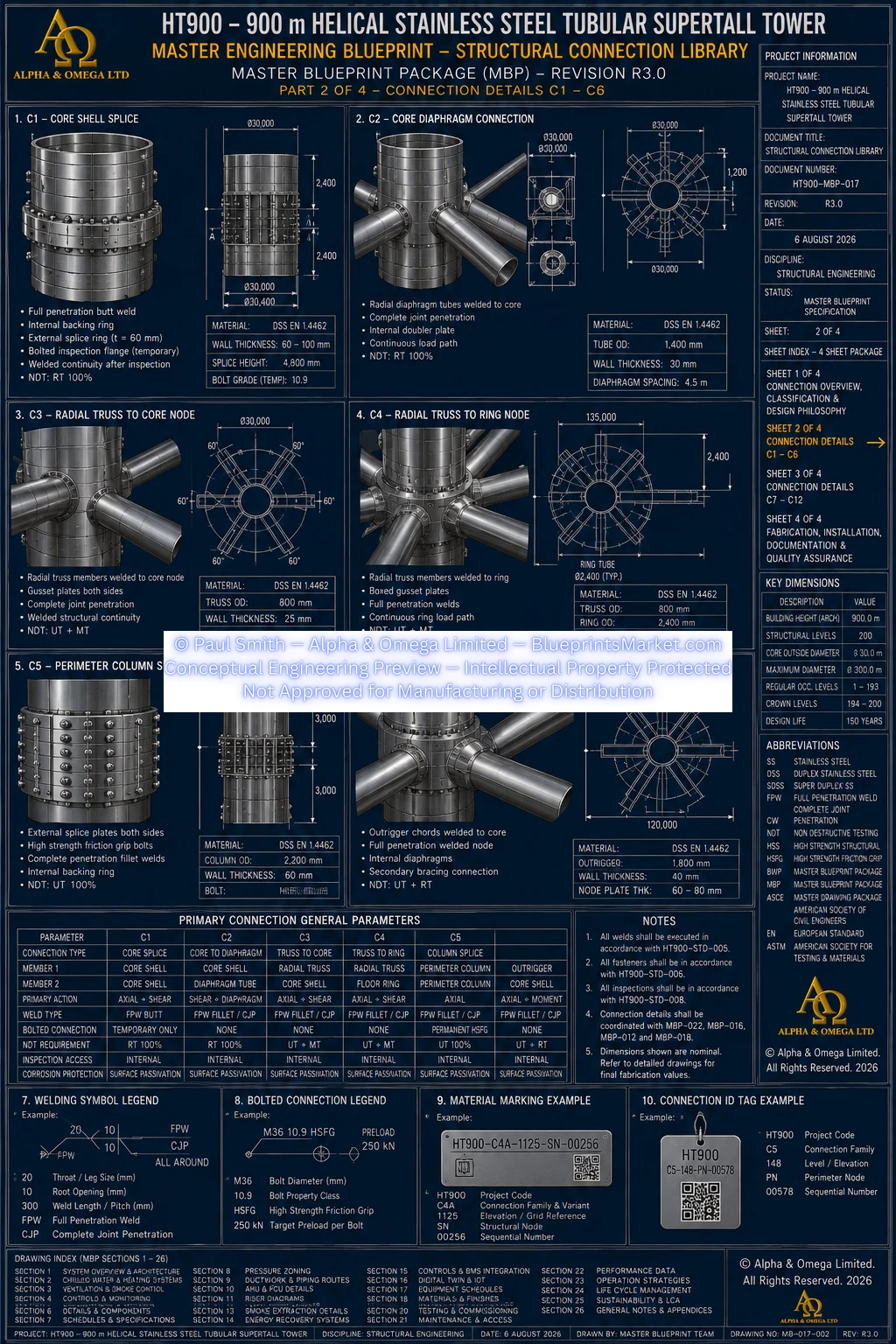
HT900-MBP-017 — STRUCTURAL CONNECTION LIBRARY
Copyright — Alpha & Omega Limited
All blueprint files, CAD parameters, architectural concepts, engineering specifications, and written content are the exclusive intellectual property of Alpha & Omega Limited. No part of the Stainless‑Steel Skyscraper Blueprint Package may be reproduced, distributed, or adapted without written consent.
Licensing, Copyright & Patent Restrictions
This engineering system and all associated blueprint materials, CAD files, diagrams, schematics, dimensional tables, and technical narratives are licensed, not sold, and remain the exclusive intellectual property of Alpha & Omega Limited.
This product is not eligible for patenting by any purchaser, user, organization, or third party. Patent filings, provisional patents, utility models, derivative patents, reverse‑engineering for patent purposes, and intellectual property claims are strictly prohibited.
Redistribution, resale, sublicensing, public posting, dataset inclusion, or any form of unauthorized duplication of blueprint materials, CAD files, diagrams, or engineering concepts is strictly prohibited. No license tier grants ownership, patent rights, or rights to file for intellectual property protection.
All architectural & engineering systems are conceptual and require full professional engineering validation before any real‑world use, construction, prototyping, or structural implementation.
Full legal details are available in the Terms & Conditions .