H.E.R.P.S — Pump Bearings, Rotor Support, Housings & Lubrication System
HERPS-VOL-04 — Revision D R2.0
Hybrid Energy Recovery Pump System (H.E.R.P.S)
Revision D Bearing & Rotor-Support Architecture
The H.E.R.P.S Revision D R2.0 pump bearing system provides the
mechanical support, axial location, radial restraint, controlled thermal
growth, lubrication and condition-monitoring architecture for the
three-stage centrifugal pump rotor.
Revision D uses a two-support arrangement consisting of a drive-end
locating bearing pair and a non-drive-end floating bearing. This allows
the rotor to remain accurately positioned while accommodating controlled
differential thermal growth through the floating end.
- Drive-end locating and thrust-bearing system
- Non-drive-end floating radial bearing
- Precision-machined bearing housings
- Oil-bath lubrication architecture
- Drive-end constant-level oil control
- Labyrinth shaft interfaces
- Bearing-temperature monitoring
- Orthogonal vibration monitoring
- Oil-condition inspection provisions
- Electrical bearing-current mitigation interface
- Controlled bearing service access
- Rotordynamic and bearing-life validation
HERPS Revision D Operating Context
| Parameter |
Revision D R2.0 Baseline |
| Machine Architecture |
Horizontal three-stage centrifugal industrial water pump |
| Rated Duty |
150 L/s at 80 m TDH |
| Nominal Pump Speed |
2,900 rpm |
| Controlled Speed Range |
1,500–3,600 rpm, subject to validated exclusion bands |
| Main Drive Context |
160 kW liquid-cooled high-efficiency SynRM / compliant equivalent baseline |
| Bearing Arrangement |
Drive-end locating / non-drive-end floating |
| Common Pump / Motor Axis |
Y = 0; Z = +800 mm |
| Minimum Local Bearing Service Access |
≥400 mm at each bearing housing |
Drive-End Locating Bearing System
The drive end establishes the principal axial datum for the pump rotor
and carries radial loading together with residual bidirectional axial
thrust remaining after the pump's hydraulic thrust-balancing system.
| Feature |
Revision D Baseline |
| Bearing Family |
7314-class angular-contact bearings |
| Arrangement |
DB / back-to-back locating pair |
| Quantity |
2 |
| Nominal Envelope per Bearing |
70 mm bore × 150 mm OD × 35 mm width |
| Primary Function |
Radial support, residual bidirectional thrust and rotor axial datum |
| Housing Bore |
150 H7 design-development interface |
| Temperature Monitoring |
Independent Pt100 monitoring at each DE bearing row |
Non-Drive-End Floating Bearing
The non-drive-end bearing is intentionally retained as the floating
radial support. It supports the rotor while allowing controlled axial
thermal growth and is not intended to become a second fixed axial datum.
| Feature |
Revision D Baseline |
| Bearing Family |
NU314-class cylindrical-roller bearing |
| Quantity |
1 |
| Nominal Envelope |
70 mm bore × 150 mm OD × 35 mm width |
| Function |
Radial support with controlled axial thermal float |
| Housing Bore |
150 H7 design-development interface |
| Temperature Monitoring |
Pt100 bearing-temperature channel |
| Lubrication Baseline |
ISO VG46 oil-bath system |
Rotor Axial & Radial Load Management
The bearing architecture works with the pump hydraulic system rather than
functioning as an isolated component. Hydraulic thrust is reduced through
the pump's balancing arrangement before residual axial loading reaches
the drive-end locating pair.
Radial hydraulic reactions, rotor weight, impeller unbalance, coupling
influence and transient forces pass through the pump shaft journals into
the DE and NDE bearing supports.
- DE locating pair establishes the rotor axial datum.
- NDE cylindrical-roller bearing provides floating radial support.
- NDE axial freedom accommodates differential thermal growth.
- Bearing stiffness and damping form part of the rotordynamic model.
- Operating exclusion bands can be incorporated into drive/control logic where validation requires.
- Vibration signatures are captured during acceptance testing for later condition monitoring.
Precision Bearing Housings
| Feature |
Drive End |
Non-Drive End |
| Development Envelope |
320 × 300 × 310 mm |
280 × 300 × 310 mm |
| Bearing Bore |
150 H7 |
150 H7 |
| Material Family |
17-4PH or qualified coated cast-steel / ductile-iron family |
Same qualified material family |
| Oil Volume Baseline |
3.5 L effective |
2.5 L effective |
| Local Removal Clearance |
≥400 mm |
≥400 mm |
Mounting faces and bearing bores are coordinated to the common pump shaft
datum so the housing system does not induce shaft bending or compromise
rotor alignment.
Pump Shaft & Bearing-Journal Interface
| Control |
Revision D R2.0 Interface |
| Nominal Bearing Journal |
70 k6 |
| Journal Surface Finish |
Ra ≤0.4 µm |
| Journal TIR |
≤0.015 mm |
| Shaft Straightness |
≤0.03 mm over the 1,600 mm shaft baseline |
| Assembled Rotor TIR |
≤0.05 mm at impeller OD |
Thermal-Growth Accommodation
The DE locating / NDE floating arrangement prevents the normal thermal
growth of the shaft and rotor from becoming unintended bearing thrust.
- DE bearing pair establishes axial location.
- NDE bearing remains free to accommodate controlled differential growth.
- Steady-state axial movement is monitored after thermal stabilization.
- Housing alignment and connected-machine alignment are checked against the common shaft datum.
- External piping strain must not materially alter bearing alignment.
Oil-Bath Lubrication System
Both Revision D bearing housings use an oil-bath lubrication baseline,
with the drive-end housing incorporating constant-level oil control and
direct visual level indication.
| Lubrication Feature |
Drive End |
Non-Drive End |
| Primary Lubrication |
Oil bath |
Oil bath |
| Lubricant Baseline |
ISO VG46 |
ISO VG46 |
| Oil-Level Control |
Constant-level oiler + sight glass |
Sight glass |
| Breathing |
Filtered / desiccant-filtered option |
Filtered / desiccant-filtered option |
| Drain |
Magnetic drain |
Magnetic drain |
| Condition Sampling |
Dedicated sample provision preferred |
Dedicated sample provision preferred |
Lubricant Condition & Contamination Monitoring
Revision D incorporates maintainable provisions for direct oil-level
inspection and condition-based lubrication monitoring.
- Service-visible oil-level sight glasses
- Drive-end constant-level oil control
- Filtered or desiccant-filtered breathing
- Magnetic drains for ferrous-debris inspection
- Dedicated oil-sampling provisions where required
- Oil appearance and contamination inspection
- Temperature and vibration trending alongside lubrication condition
Labyrinth Shaft Interfaces
| Parameter |
Revision D Development Baseline |
| Labyrinth Shaft Diameter |
Ø80 mm |
| Radial Clearance |
0.25–0.35 mm development baseline |
| DE Arrangement |
Labyrinth at bearing-housing shaft penetration |
| NDE Arrangement |
Equivalent labyrinth interface |
| Acceptance Principle |
No rub throughout validated speed, runout, thermal-growth and rotor-deflection envelope |
Bearing Temperature Monitoring
Revision D provides three dedicated Pt100 bearing-temperature channels:
- Drive-end bearing row 1 temperature
- Drive-end bearing row 2 temperature
- Non-drive-end bearing temperature
Final alarm and trip thresholds remain coordinated with the selected
bearing, lubricant, controls architecture and validated FAT operating
signatures rather than being assigned arbitrarily.
Permanent Bearing Vibration Monitoring
Both bearing housings provide orthogonal monitoring positions so rotor
and bearing condition can be trended across the machine's released
operating envelope.
| Location |
Monitoring Direction |
| Drive End |
X / horizontal |
| Drive End |
Y / orthogonal |
| Non-Drive End |
X / horizontal |
| Non-Drive End |
Y / orthogonal |
Baseline vibration signatures established during commissioning and
acceptance testing provide the reference for later condition-based
maintenance and degradation assessment.
Electrical Bearing-Current Protection Interface
Revision D explicitly coordinates the bearing architecture with the
variable-frequency drive and motor grounding system so electrical
bearing-current exposure can be addressed where engineering analysis
determines that mitigation is required.
- Insulated bearing or insulated bearing-ring provisions where required
- Shaft-grounding ring or brush where appropriate
- Coordination with motor and VFD manufacturer provisions
- Intentional skid and housing protective bonding
- Inspection for electrical fluting or pitting during maintenance
- Temperature and vibration trending for bearing-condition assessment
Service Access & Bearing Removability
Revision D incorporates bearing serviceability into the package layout
instead of treating it as an afterthought.
- ≥400 mm local clear access at both DE and NDE bearing housings
- ≥2,000 mm common rotor / shaft withdrawal envelope
- Housing covers remain removable in the installed machine
- RTD and vibration wiring can be disconnected for maintenance
- Sight glasses, breathers, oilers, drains and sampling points remain accessible
- Bearing service does not require removal of unrelated permanent DN300 piping or electrical cabinets
- Final extraction paths are verified through coordinated CAD
Condition-Based Bearing Maintenance
Revision D maintenance uses measured operating history and accepted
commissioning signatures rather than relying solely on instantaneous
alarm thresholds.
- Trend bearing temperatures against commissioning baseline
- Trend vibration signatures and spectral changes
- Inspect oil level and leakage
- Inspect breathers according to condition and environment
- Inspect magnetic drains for abnormal metallic debris
- Use oil sampling where the condition-monitoring plan requires
- Inspect for electrical fluting or pitting where VFD exposure exists
- Verify alignment, axial float and free rotation after bearing replacement
Bearing-System Failure Controls
Mechanical Controls
- Controlled locating/floating architecture
- Precision shaft-journal and housing fits
- Rotor runout control
- Thermal-growth accommodation
- Housing alignment control
Lubrication Controls
- Oil-bath lubrication
- Drive-end constant-level oiler
- Visible oil-level indication
- Filtered breathing
- Magnetic debris inspection
Monitoring Controls
- Three Pt100 temperature channels
- Four orthogonal vibration channels
- Baseline vibration signatures
- Oil-condition inspection
Electrical Controls
- Bearing-current exposure assessment
- Insulation strategy where required
- Shaft-grounding strategy where required
- Protective bonding coordination
Rotordynamic, Bearing-Life & Design Validation
Revision D intentionally distinguishes between established mechanical
interfaces and values that still require selected-vendor data or
engineering validation.
- Hydraulic radial and axial bearing-load confirmation
- Rotordynamic stiffness and damping validation
- Critical-speed and operating-band verification
- Bearing-life calculation using selected OEM data
- Lubricant viscosity and temperature verification
- Preload, endplay and internal-clearance determination
- Electrical bearing-current analysis
- Final CAD tolerance and service-stack validation
- FAT/SAT temperature and vibration acceptance
FAT & Commissioning Acceptance
- Correct released lubricant and oil level
- No visible lubrication leakage or contamination
- Free hand rotation with no roughness or labyrinth contact
- Bearing-temperature stabilization within released limits
- Validated speed sweep without prohibited continuous resonance
- Stable drive-end axial location
- Verified non-drive-end thermal float
- Functional Pt100 temperature channels
- Functional DE/NDE vibration channels
- Verification of required electrical bearing-current provisions
- No abnormal noise, rubbing, discoloration or excessive debris after operation
Revision D Engineering Status
HERPS-VOL-04 Revision D R2.0 is a consolidated design-development
bearing, housing and lubrication volume. It defines the bearing
architecture, functional interfaces, lubrication functions, monitoring
provisions, maintenance philosophy and validation boundaries.
It is not represented as fabrication-final or as-built. Supplier-final
bearing details, exact preload and endplay, final bearing-life result,
final lubricant product and fill level, supplier housing internals,
selected electrical bearing-current mitigation hardware and other
vendor-controlled refinements remain subject to the applicable engineering
and validation process.
Final measured configuration becomes authoritative only after the
applicable testing, acceptance and as-built configuration process.
Explore the Complete H.E.R.P.S Revision D System
The pump bearing, rotor-support, housing and lubrication architecture is
one subsystem within the complete H.E.R.P.S Revision D multi-volume
conceptual engineering platform.
View the Complete HERPS System
Contact Blueprints Market for product,
licensing and engineering-package enquiries.
VOLUME 04 — PUMP BEARINGS / HOUSINGS / LUBRICATION
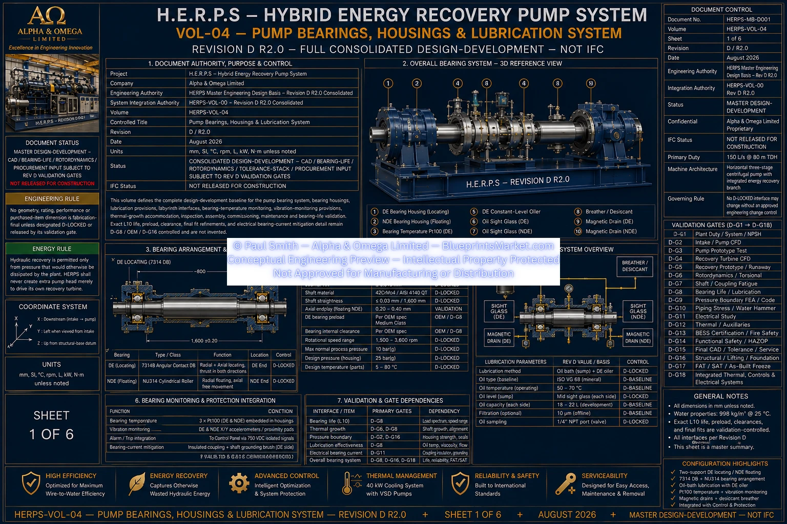
© Paul Smith — Alpha & Omega Limited — PlatformClouds.com — Conceptual Engineering Preview — Not Approved for Manufacturing
HERPS-VOL-04-PUMP-BEARINGS-HOUSINGS-AND-LUBRICATION-SYSTEM-SHEET-1-OF-6-REV-D-R2.0.webp
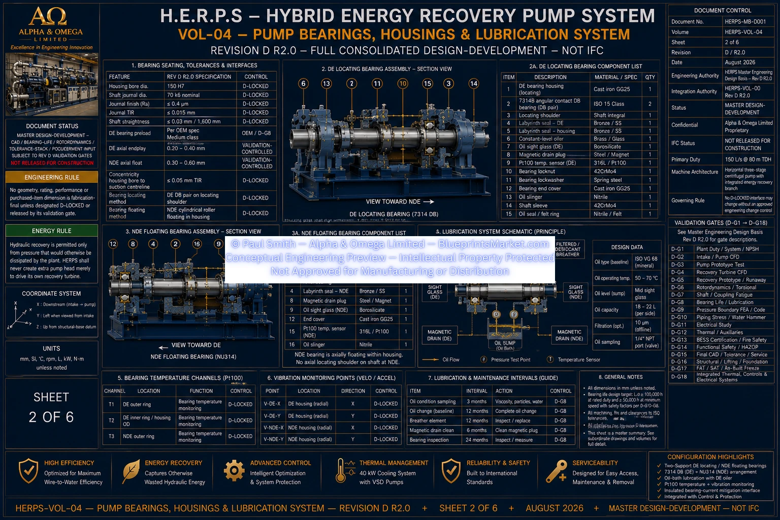
© Paul Smith — Alpha & Omega Limited — PlatformClouds.com — Conceptual Engineering Preview — Not Approved for Manufacturing
HERPS-VOL-04-PUMP-BEARINGS-HOUSINGS-AND-LUBRICATION-SYSTEM-SHEET-2-OF-6-REV-D-R2.0.webp
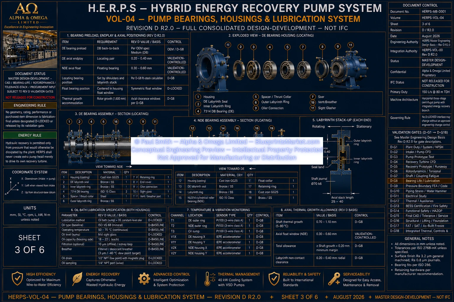
© Paul Smith — Alpha & Omega Limited — PlatformClouds.com — Conceptual Engineering Preview — Not Approved for Manufacturing
HERPS-VOL-04-PUMP-BEARINGS-HOUSINGS-AND-LUBRICATION-SYSTEM-SHEET-3-OF-6-REV-D-R2.0.webp
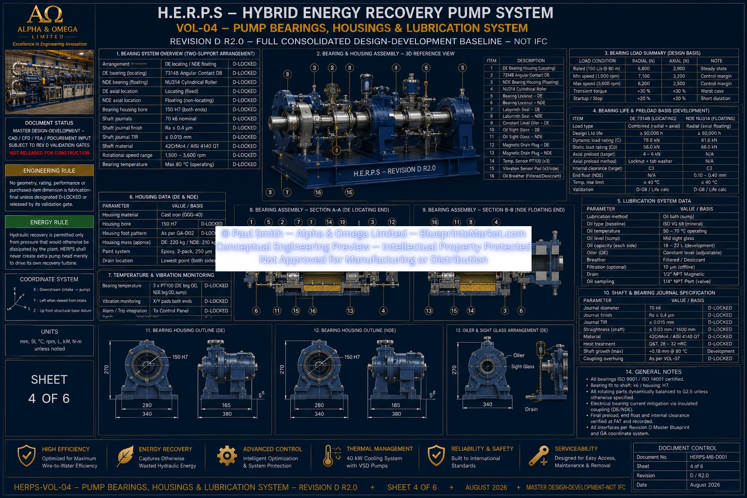
© Paul Smith — Alpha & Omega Limited — PlatformClouds.com — Conceptual Engineering Preview — Not Approved for Manufacturing
HERPS-VOL-04-PUMP-BEARINGS-HOUSINGS-AND-LUBRICATION-SYSTEM-SHEET-4-OF-6-REV-D-R2.0.webp
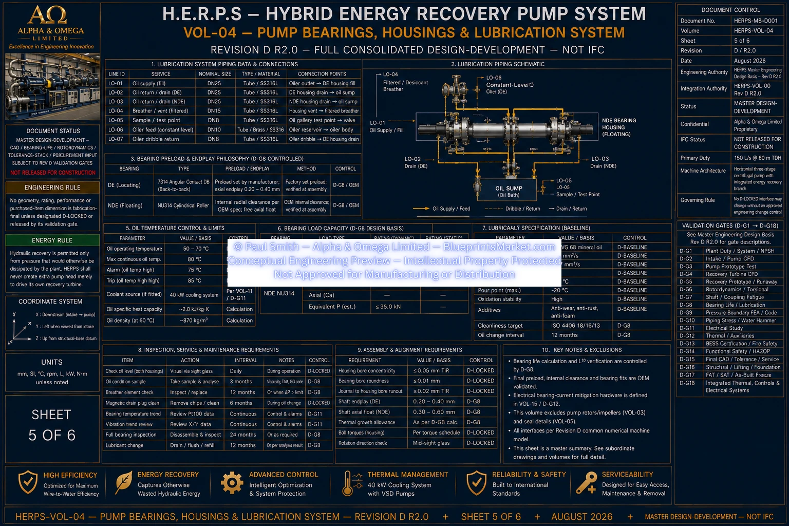
© Paul Smith — Alpha & Omega Limited — PlatformClouds.com — Conceptual Engineering Preview — Not Approved for Manufacturing
HERPS-VOL-04-PUMP-BEARINGS-HOUSINGS-AND-LUBRICATION-SYSTEM-SHEET-5-OF-6-REV-D-R2.0.webp
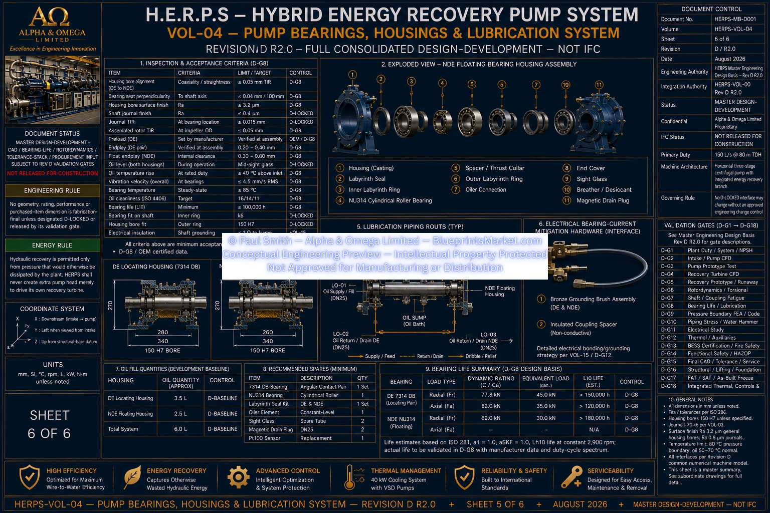
© Paul Smith — Alpha & Omega Limited — PlatformClouds.com — Conceptual Engineering Preview — Not Approved for Manufacturing
HERPS-VOL-04-PUMP-BEARINGS-HOUSINGS-AND-LUBRICATION-SYSTEM-SHEET-6-OF-6-REV-D-R2.0.webp
