© Paul Smith — Alpha & Omega Limited — PlatformClouds.com —
Conceptual Engineering Preview — Not Approved for Manufacturing
HERPS-VOL-15-PLC-HMI-SCADA-INSTRUMENTATION-AND-FIELD-IO-REV-D-R2.0.webp

H.E.R.P.S — HYBRID ENERGY RECOVERY PUMP SYSTEM
HERPS-VOL-15 — Revision D R2.0
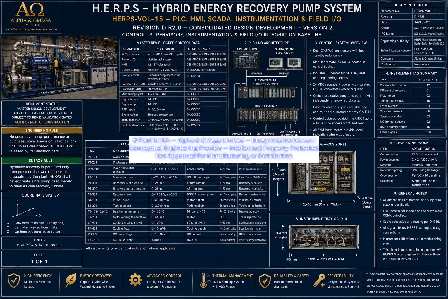
The H.E.R.P.S Revision D control and instrumentation architecture integrates the package PLC/controller, remote I/O, local HMI, SCADA/supervisory interfaces, field instrumentation, junction boxes, shielded instrumentation cabling, calibration requirements and controlled tag schedules into one coordinated automation layer.
Central package controller providing normal process control, sequence management, supervisory logic and field-I/O coordination.
Distributed I/O architecture used to interface package sensors, actuators and monitored equipment with the main control system.
Operator interface for system status, process values, alarms, operating modes, trends and controlled operator commands.
Supervisory interface for plant-level monitoring, data exchange, event visibility and operational integration.
Redundant 24 VDC power-supply architecture with engineered DC ride-through.
Critical protective functions retain independent hardwired action rather than depending solely on the normal PLC control layer.
Revision D Volume 15 coordinates the principal instrumentation required to monitor hydraulic, mechanical and thermal operation throughout the H.E.R.P.S package.
Pressure instrumentation for suction, discharge, recovery and other monitored hydraulic locations.
Differential-pressure measurement where required for monitored hydraulic equipment and process functions.
Flow instrumentation for process and energy-recovery monitoring.
Rotational-speed measurement for monitored rotating equipment.
Vibration measurement supporting rotating-equipment condition monitoring and operating-state supervision.
Temperature instrumentation across bearings, motors, power electronics and other thermally monitored subsystems.
Level instrumentation where required by lubrication, cooling, storage or auxiliary systems.
The Revision D control cabinet occupies the coordinated GA-D09 package zone:
| Axis | Coordinated Zone |
|---|---|
| X | 7,200–8,100 mm |
| Y | -1,200 to -400 mm |
| Z | 300–2,400 mm |
Final selected PLC, HMI, remote-I/O and cabinet hardware remains vendor-controlled until the corresponding equipment is selected and certified data are released.
The coordinated Revision D instrument tray occupies the GA-D14 longitudinal package zone:
| Axis | Coordinated Zone |
|---|---|
| X | 0–10,200 mm |
| Y | +100 to +250 mm |
| Z | 1,700–1,950 mm |
Field instrumentation uses coordinated junction boxes, shielded instrument cabling, appropriate cable segregation and controlled termination practices.
Instrument and equipment signals are integrated through the Revision D field-I/O architecture for normal process control, monitoring, alarming and supervisory visibility.
The local HMI and supervisory interface provide operator visibility into H.E.R.P.S process conditions and package state without replacing the independent hardwired protection architecture.
Hydraulic, mechanical, electrical and energy-recovery operating state visibility.
Active alarm, warning and event presentation within the released alarm-management philosophy.
Historical and real-time trend display for monitored process and condition variables.
Visibility and controlled selection of permitted package operating modes.
Equipment status and monitored condition data supporting troubleshooting and service activities.
Volume 15 includes the field installation, calibration and tag-control framework required to ensure that instrumentation shown in the engineering records corresponds to the actual installed signal channels and control database.
HERPS-VOL-15 defines the complete source-supported control, supervisory, instrumentation and field-I/O integration baseline, but does not fabricate final vendor models, final network IP plans, final transmitter dimensions, hazardous-area classifications, SIL/PL claims or final trip thresholds where those remain controlled by vendor, HAZOP, functional-safety, electrical-study or site-release processes.
Critical protective actions are handled separately within the H.E.R.P.S functional-safety and hardwired-trip architecture rather than being assumed to exist only in the normal PLC software.
Master Design-Development — Not IFC — Not Approved for Manufacturing.
HERPS-VOL-15-PLC-HMI-SCADA-INSTRUMENTATION-AND-FIELD-IO-REV-D-R2.0.webp