© Paul Smith — Alpha & Omega Limited — PlatformClouds.com — Conceptual Engineering Preview — Not Approved for Manufacturing
HERPS-VOL-13-COMMON-DC-LINK-DC-DC-CONVERSION-AND-SUPERCAPACITOR-SYSTEM-REV-D-R2.0.webp

H.E.R.P.S — HYBRID ENERGY RECOVERY PUMP SYSTEM
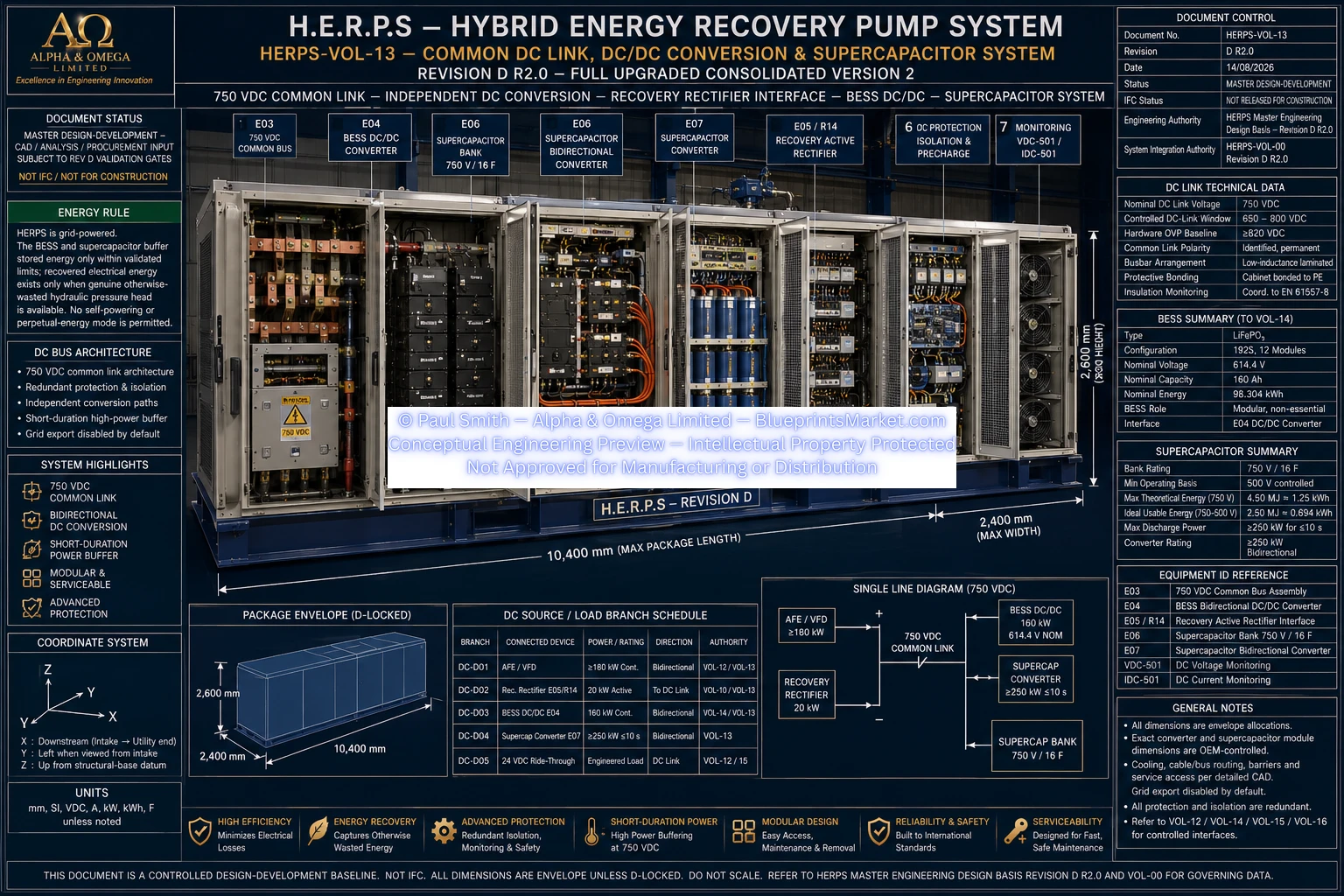
Revision D R2.0 controlled design-development architecture for the H.E.R.P.S 750 VDC common high-voltage DC link, independent bidirectional DC/DC conversion, recovered-energy interface, transient supercapacitor storage, monitoring, isolation and protection system.
HERPS-VOL-13 — Revision D R2.0
Controlled Design-Development Document — Not Released for Construction
HERPS-VOL-13 controls the Revision D common high-voltage DC link and its independent conversion, transient-storage, monitoring, isolation and protection architecture.
The system uses a 750 VDC nominal common link with a controlled operating window of 650–800 VDC. The system-level hardware overvoltage-protection baseline is ≥820 VDC, subject to final OEM and electrical protection coordination.
The common link coordinates the regenerative AFE/VFD, recovery active rectifier, BESS bidirectional DC/DC converter, supercapacitor converter and engineered control-power ride-through architecture.
| System Parameter | Revision D R2.0 Baseline |
|---|---|
| Common DC Link | 750 VDC nominal |
| Controlled DC-Link Window | 650–800 VDC |
| Hardware OVP Baseline | ≥820 VDC system-level baseline |
| AFE/VFD Interface | ≥180 kW continuous regenerative drive class |
| Recovery Active Rectifier | 20 kW class |
| BESS | 192S, 160 Ah, 614.4 V nominal, 98.304 kWh LiFePO₄ |
| BESS DC/DC Converter | 160 kW continuous bidirectional; 200 kW ≤30 s |
| Supercapacitor | 750 VDC class, 16 F nominal |
| Supercapacitor Minimum Controlled Basis | 500 V |
| Supercapacitor Converter | ≥250 kW short-duration bidirectional |
| DC-Link Voltage Measurement | VDC-501 — 0–1000 VDC isolated |
| DC-Link Current Measurement | IDC-501 — ±400 A Hall/fluxgate baseline |
| Grid Export | Disabled unless separately engineered and approved |
The E04 converter provides the controlled bidirectional electrical interface between the 614.4 V nominal 192S LiFePO₄ BESS and the 750 VDC nominal common link.
The BESS is hydraulically non-essential and software-isolatable. Normal grid-powered hydraulic operation is intended to remain available with the BESS isolated when all other operating permissives are satisfied.
The E05/R14 recovery interface uses a 20 kW active rectifier between the variable-frequency 15 kW-class PMG and the 750 VDC common link.
Recovered electrical energy is injected only when genuine otherwise-wasted hydraulic pressure head is available. Recovery injection is reduced or stopped as DC-link acceptance limits are approached.
The Revision D nominal net recovered-electrical target is approximately 8.25 kW only at the validated recovery design condition and efficiency targets. The 20 kW rectifier remains sized with margin.
E06 is a 750 VDC-class, 16 F nominal supercapacitor bank dedicated to short-duration transient-energy management rather than long-duration energy storage.
| Parameter | Revision D Value |
|---|---|
| Voltage Class | 750 VDC |
| Equivalent Capacitance | 16 F nominal |
| Minimum Controlled Operating Basis | 500 V |
| Maximum Theoretical Energy at 750 V | 4.50 MJ = 1.25 kWh |
| Ideal Usable Energy — 750 V to 500 V | 2.50 MJ ≈ 0.694 kWh |
| Transient Role | ≈250 kW for ≈10 s ideal-energy basis |
The 16 F rating is the system-level equivalent capacitance. Certified cell count, cell voltage, balancing, ESR, internal busbars, module fusing, venting, monitoring and physical module construction remain supplier and Revision D release controlled.
E07 provides the high-power bidirectional interface between the supercapacitor bank and the common DC link.
The supercapacitor subsystem is not intended to function as a long-duration BESS substitute.
Any topology capable of energizing de-energized DC capacitance requires controlled precharge before its main current path closes. Precharge functions across the AFE/VFD, common link, BESS DC/DC, BESS pack and supercapacitor converter are coordinated to prevent uncontrolled energization or competing precharge paths.
DC overvoltage, branch overcurrent, bus fault forces, BESS fault contribution, supercapacitor fault contribution, recovery-source faults and insulation faults are subject to coordinated protection and Revision D validation.
An emergency stop or opened isolator does not by itself establish that all stored DC energy has been removed. Maintenance access requires positive isolation, controlled discharge and absence-of-voltage verification under the approved LOTO procedure.
The primary VOL-13 DC conversion and supercapacitor equipment allocation is:
GA-D10 is a package allocation rather than proof that every final OEM converter and supercapacitor module configuration fits within one exact cabinet. Final module geometry, barriers, cable bend radii, cooling, clearances and removal access remain subject to vendor selection, CAD coordination and validation.
H.E.R.P.S is grid-powered. The BESS and supercapacitor provide stored-energy buffering only within validated operating limits.
Recovered electrical energy exists only when genuine otherwise-wasted hydraulic pressure head is available. The common-link architecture does not authorize self-powering, perpetual-energy operation or uncontrolled grid export.
HERPS-VOL-13 is a controlled Revision D design-development baseline. D-LOCKED interfaces are mandatory across coordinated Revision D volumes, CAD, drawings, renders, P&IDs and BOMs unless changed through formal engineering change control.
OEM-final semiconductor topology, switching frequency, magnetics, certified supercapacitor construction, ESR, final DC fuse and breaker ratings, busbar geometry, creepage and clearance, precharge/discharge component values, cooling flow, fault-current/SCCR values and certified isolation details remain subject to their applicable engineering, OEM and validation release gates.
This page presents the H.E.R.P.S HERPS-VOL-13 Revision D R2.0 conceptual engineering and controlled design-development architecture for technical review and blueprint documentation.
Document status: Master Design-Development — CAD / Analysis / Procurement Input Subject to Revision D Validation Gates.
IFC status: Not Released for Construction.
HERPS-VOL-13-COMMON-DC-LINK-DC-DC-CONVERSION-AND-SUPERCAPACITOR-SYSTEM-REV-D-R2.0.webp